Interface & Application Programming
Since I've wrote quite a few softwares to interface with my boards in the previous weeks, I decided to start working on my final project, and also fab more boards to make use of the idle PCB mill nobody was using during thanksgiving week.
You can see videos of how I used 5 phototransistors to locate a light source on a plane, and drove three interactive demos in openFrameworks via serial communication below, or read about the full project here.
A theramin:
A (5 key) piano:
A 3D scene where the position of the virtual light source is controlled by that of the real light source:
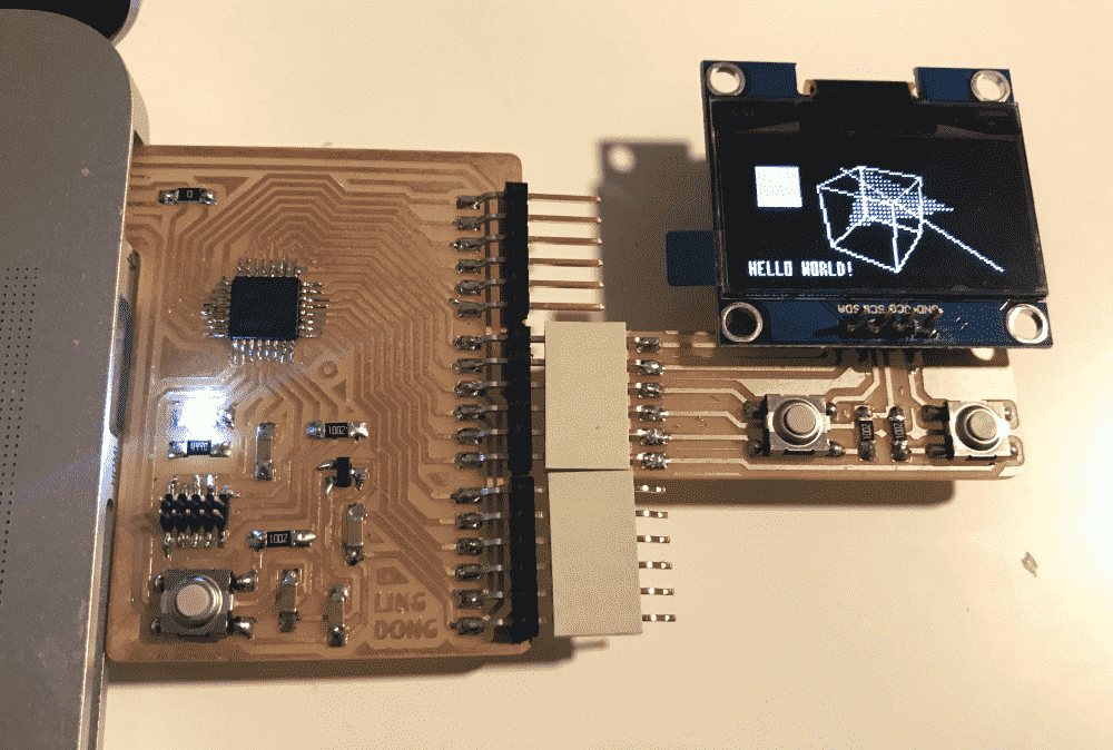
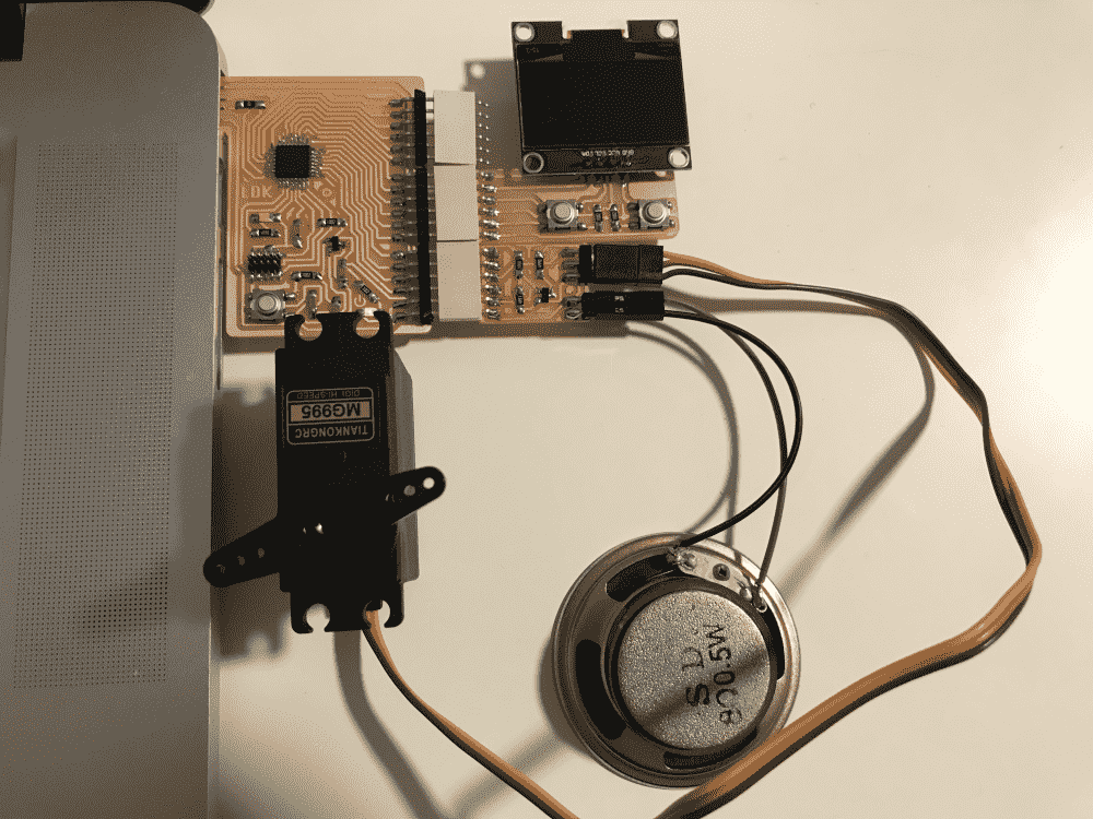
You can see a video of how I wrote a web interface to talk to the RN4871 via bluetooth, which talks to a SAMD21E microcontroller, which controls a servo and also pass on the command to a SAMD11D microcontroller via serial, which controls a OLED display via I2C, and how I managed to send a 32x32 image via bluetooth below, or or read about the full project here.
You can see a video of how I wrote a Processing program to capture keystrokes on my laptop keyboard, and send them via serial to the microcontroller, which controls a speaker to play notes, as well as an OLED to show a tiny “piano roll” visualization, or read about the full project here.
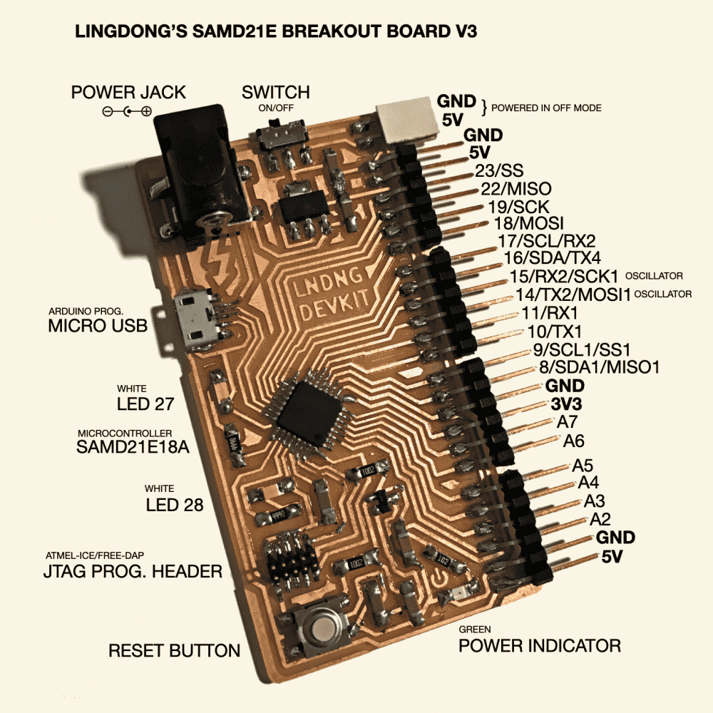
The rest of this page will be about how I made version three of my breakout board and what's so cool about it.
Breakout Board v3
The issue with version 1 of my breakout board is that it only exposed a 3V3 pin but not a 5V one, rendering it useless for 5V components like servos and speakers. This is fixed in version 2 of my breakout board, which has been working great. I've made quite a few “modules” for it since: OLED's, speakers, servos, bluetooth, serial, etc. However, I'm still striving for a “dream” design:
- I want to be able to have an external power supply via powerjack, because I heard that servos, which I need many of in my final project, are greedy for power.
- I want to try out the female microUSB connector I found in the shop. They look shiny and cool, and feel more reliable than the wobbly cutout male USB with solder blobs on top and business cards underneath.
- I want to have more pins exposed. The previous two versions have 15-ish pins broken out, while the SAMD21E has 20-ish free pins.
- I want to be able to do SPI communication. I was under the false impression that pins labelled “oscillators” on the datasheet are “useless”, but apparently they're needed for SPI. The previous two designs cannot do hardware SPI due to leaving out these.
What I really like about my two earlier designs that I want to keep:
- All the pins are laid out on the same edge. This allows me to make “mating” boards that utilize some or all of the pins, and plug them into the breakout board directly without having to use jumper wires.
- The boards are fairly small and portable, and the traces are tightly and optimally packed. They only require one 0 ohm resistor “jump”.
- The pins are “lying down” instead of “standing up”. The only “standing up” one is the tiny JTAG header. I like to keep my boards in my pockets, and “standing up” headers poke through my pocket and stab me. Ouch!
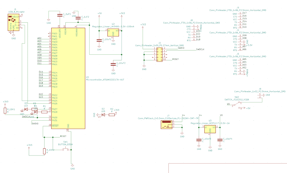
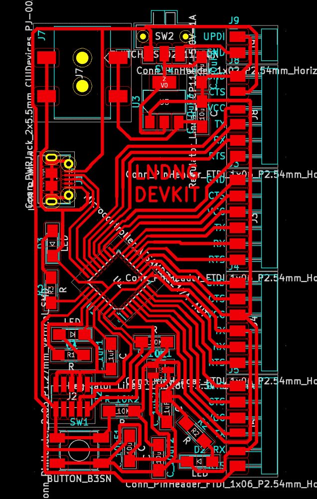
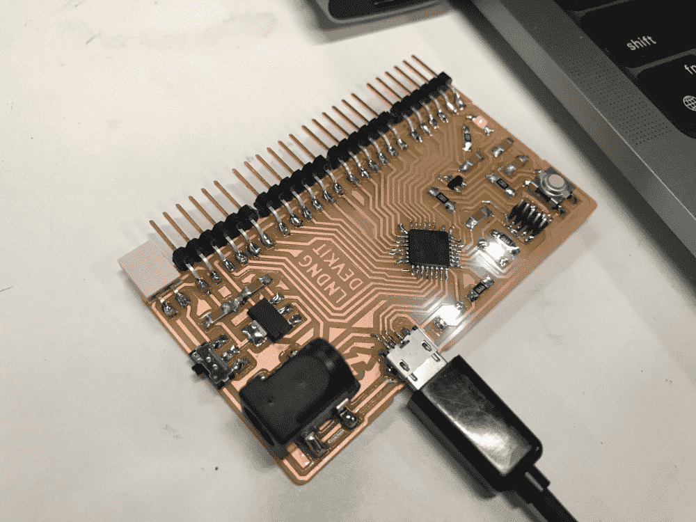
With these principles in mind I designed version 3 of my breakout board.
You can see that I added a switch for the powerjack, to turn it on or off, because I wasn't sure if I was connecting the powerjack component correctly, and was afraid that my board (or even worse, myself) will get electrocuted when I plug in the external power. In retrospect, that would only delay the death of my board (or myself) from the moment of plugging to that of switching, but anyways, it's nice to have a switch. I saw the switches in the shop and wanted to try them out.
I routed the board on the subway, on my way to school to fabricate the board.
I checked the two power adapters I found at home (don't even know why I have them), and it seemed that one doesn't fit into any jack in the shop, while the other one fits into the large “2x5.5mm” jack, so I used the footprint for that one.
I turned the MCU by 45 degrees, because I realized that this would make the traces a lot more efficient. Couldn't believe I didn't think of that for my two previous boards. With the newly earned space, I can now print my moniker in a large font right near the center of the board.
But the coolest thing to note is that this board does not use any 0-ohm resistors at all. It's my first jump-free SAMD21E board. This was possible because the microUSB connector is female, meaning that the order of its pins are inverted from the male USB connector I've been using. The main reason that all my previous SAMD21E boards have one jump is because the USB D+/D- lines are inverted from the MCU D+/D- pins. For the female connector, the D+/D- are finally in the “correct” order. I also had to use a tiny “cheat”: I shortened two pads near one corner of the SAMD21E, such that I could run a trace out of the corner. (Now that I have less terrible soldering skills, I become more ruthless in tampering footprints to my advantage)
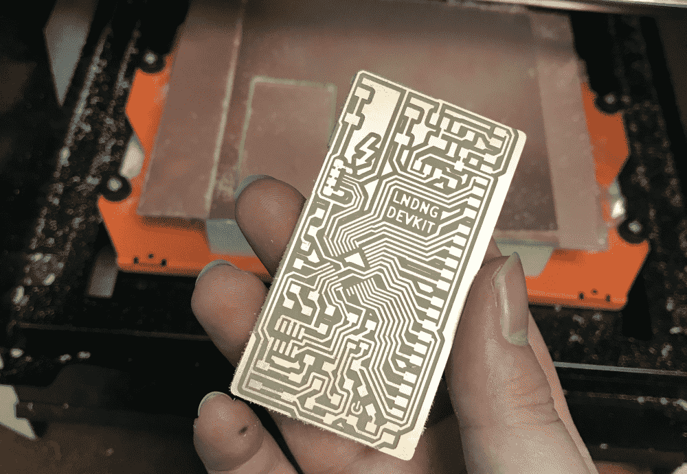
I failed in my first attempt to mill the board: the traces were carved way too deep, and consequently broke the endmill, despite the fact that I used the default settings on mods and properly zeroed the machine.
I reasoned that the copper board I was using was terribly warped. I confirmed my hypothesis by zeroing the endmill in the center of the board, then moving it to a corner of the board, and finding the endmill to be dangling in mid-air.
I realized that the whole stack of one-sided boards in the shop were all terribly warped. I believe it is because the boards come in tightly-bound packages which constrain them from warpping. Someone unpacked all the boards, causing the boards to go “freestyle” in their shapes.
I managed to fix this issue by finding a bigger two-sided board which was not warping as the sacrificial bedding, and bending/rolling the warped board in the opposite direction of the warp when taping it down onto the straight board. I smacked the boards with my palm to make sure they were not bouncy. It finally milled perfectly.
I was summoned to a dinner party so I didn't have time to stuff the board on that day. I recently bought an iron for soldering at home, so I figured it was a good chance to try it out. However, my iron was really terrible. Or it could be my solder wire, or flux, or a combination of the three. My soldering skill suddenly degenerated to week one. With the soldering tools at the shop, I feel that I can get the solder to flow wherever I want it to. It's a beautiful experience. With my kit at home, the solder feels like gross toothpaste and just unpleasant to work with. So I decided to pay another visit to the shop the next day to get the stuffs soldered with my favorite iron, favorite solder and favorite flux (pictured below).
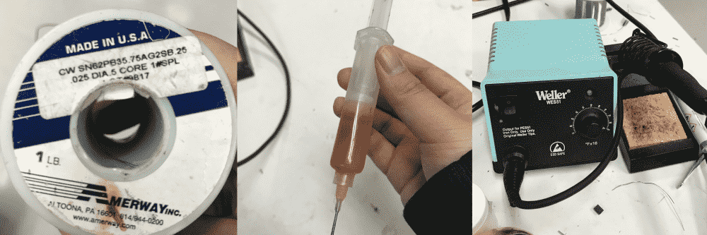
Looking up the brand I realized that the solder wire by itself is nearly twice as expensive as my entire kit at home combined. I guess I was cheaping out again.
Anyways, with my favorite tools I got the board stuffed without too much difficulty, except for two places:
I didn't realize that the circular “decorations” on the power jack's footprint actually mean holes that I need to drill when milling. I thought they're just graphics for indicating direction, and simply deleted them in the exported image. Now the “warts” at the bottom of the power jack are sticking out and preventing the pins from touching the pads.
But that didn't prove to be much of a problem. I simply soldered them by adding more solder.
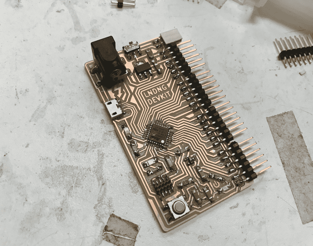
The other problem was that the metal casing (I think they're called “shields”) of the female microUSB connector was touching the traces underneath it. What makes it even more terrible is that the traces happen to be GND and 5V.
So I desoldered the connector, put a piece of double sided tape on its bottom side, confirmed that double sided tape is not conductive, and soldered the connector back onto the board, using the tape to insulate the shield from the traces underneath.
But now with the thickness of the tape, the pins of the microUSB connector were no longer touching the pads. I also shifted the microUSB a bit outward, so the pins and pads were departed in both X and Z directions.
The microUSB pins are super tiny, even tinier than the SAMD21E pins, and they're partially occluded by the shield so the iron can barely reach them from a comfortable angle. However, there are only 5 of them compared to SAMD21E's 32. So the soldering difficulty is about the same order of magnitude. Now due to my mishaps, the difficulty has been raised by roughly one order of magnitude.
But I “invented” a new soldering trick. I can fiddle with the solder and iron such that the solder reaches a certain state, resembling the quality of whip cream. By pulling from the whip cream, I can have a pointy cone of solder sticking from the tip of the iron. This pointy cone is very pointy, and can reach places the iron cannot reach, and solder joints way tinier than what the iron can usually solder. It takes some ceremony to get the solder into this ideal whip cream state, but once it is, nothing can prevent itself from getting soldered.
The next step was to see if I could get the board bootloaded and programmed and prove that the microUSB connector is working. It went well: Atmel-ICE was happy, edbg was happy, Arduino IDE was happy, phew!
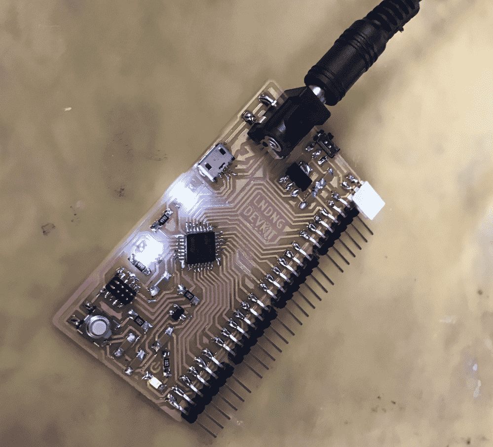
Now came the scary step: plugging in the external power supply from the 110V outlet. I've classified the potential consequences:
- Best case: it works
- Second best case: it doesn't work, but my board is not fried
- Third best case: my board is fried
- Fourth best case: I'm fried
I considered the possibilty of the fourth case. It would kinda be a pity, but I think I've lived a fulfilling life so far, so I decided to go with it.
Turned out it was the first case. I double checked with a multimeter, and was satisfied with the readings. Yay!
I've tested some new and old modules with this breakout board, and confirmed that it is functionally complete.