Output Devices
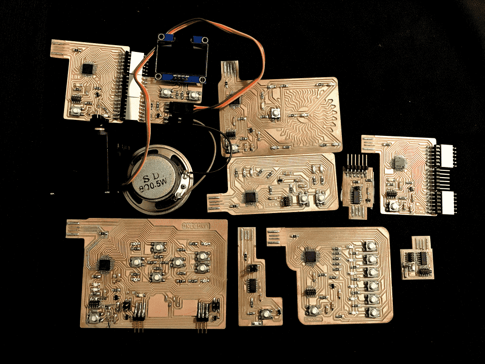
This week I was intrigued by almost all the output devices introduced. I decided to make a borad with 2 servos, 2 speakers, 1 OLED display, a couple LED's, as well as several phototransistors and buttons for input. It would be like a tiny computer! Perhaps I could use it as a handheld gaming device, or a control panel for some servo-based machine (e.g. my final project).
In the end, though I got this “monster” of a board working, I had more fun programming my breakout board with tiny detachable modules. Demos below:
A 1 bit graphics demo package. Select one out of 6 demos from the menu and view cool 2D and 3D stuff.
A tiny piano roll: note events are generated by my laptop keyboard and sent via serial to the microcontroller, and played through the speaker controlled by the microcontroller. A visualization is shown on the OLED display also controlled by the microcontroller.
More details and code can be found near the bottom of the post.
Design
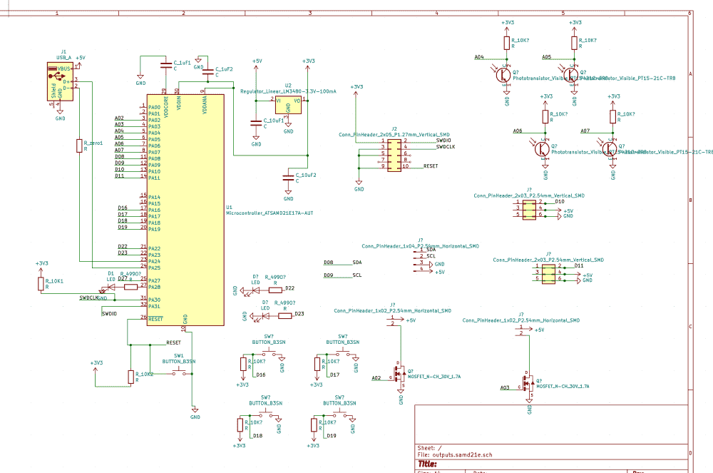
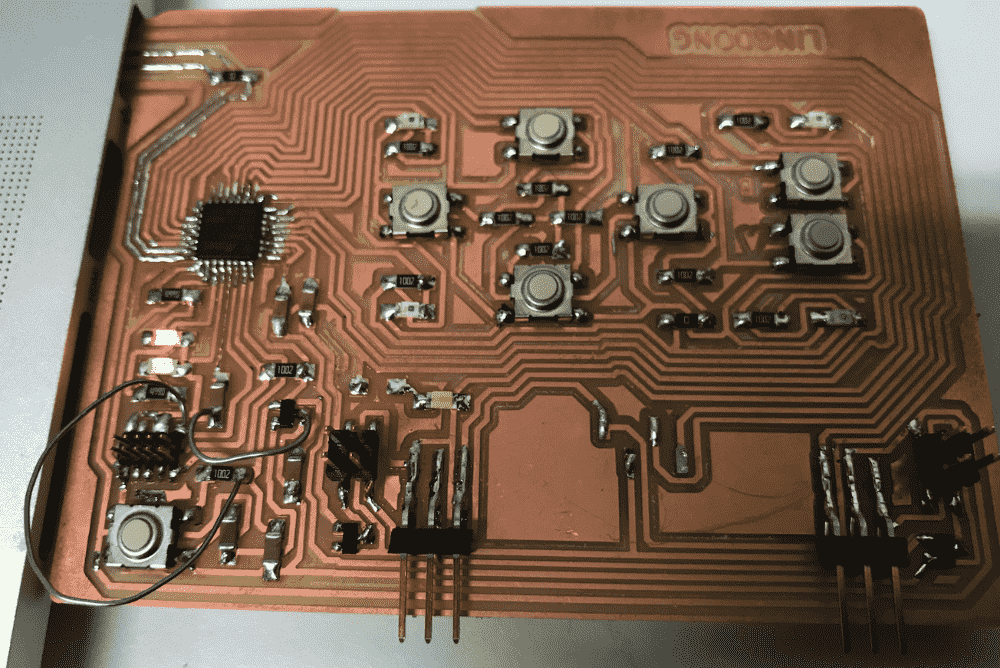
I quickly sketched out a schematic containing all the parts I wanted. I used every single pin on the SAMD21E microcontroller, so there's no waste whatsoever.
Unfortunately, it became such a nightmare to route, especially since I had a desired position on the board for each of the components.
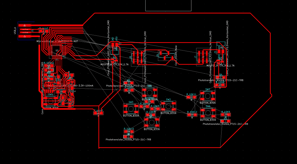
But, due to my routing skills I acquired through the previous weeks, I managed to figure out the puzzle:
It has 2 0-ohm resistors for jumps. I've never had more than one in all my previous boards. I think I could probably reduce it to one for this board too, but I was sleepy and my brain stopped working.
Tidying up also took a considerable amount of time. However, using a KiCAD feature TA Zach showed me last week, (Route > Interactive Router Settings > Shove), the process became less painful then it used to be in KiCAD.
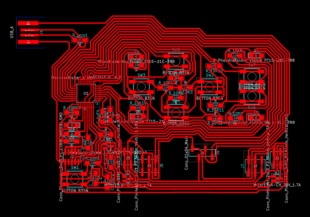
There was an interesting issue with the OLED footprint: In prof. Neil's demo video, one can see that the pins on the OLED go in the order of VCC GND SCL SDA. However, in the amazon link right beside it, one can see that in the product pictures, the order of VCC and GND are reversed. After some quick search on the Internet, I discovered that both variants exist in the world. So which one does our shop have? It was in the middle of the night and I live far away from school, so I decided to take my chances and bet on GND VCC. But I also tested to make sure that if I were wrong, it wouldn't be hard to swap the two in my routing. Luckily, I would later find myself betting on the right one.
Fabrication
I stayed up Wednesday night to route the board, slept for 3 hours in the morning, and set out to the shop to fabricate the board.
Unfortunately, it was a busy day in the milling room. Every week I try to start very early to avoid the crowd, but it seems that even Thursdays are becoming popular. I waited two hours in the line (should've spent them sleeping), and there were also people waiting to mill after me. Wow.
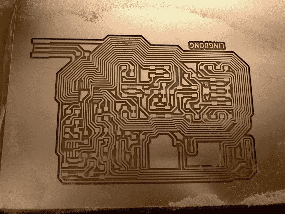
Fortunately, my monstrously large board milled perfectly the first time. Every week I become more ambitious!
When I started soldering I noticed an interesting mistake. I left some room on the board for the OLED display (bottom center in picture above), but apparently not enough. Which was strange, because I did the measurements and even added a bit of leeway when I designed it. The OLED display is flanked by two sets of pin headers for the servo motors, which protrude. So It seems that I couldn't fit in the OLED display.
Then I realized that instead of upright pin headers, I could use those FTDI ones that lie down on their sides. Then, using upright headers for the OLED, the display would sit comfortably on top of the lying pins on its sides.
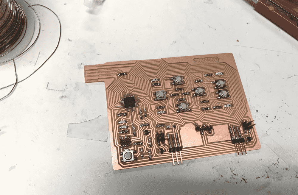
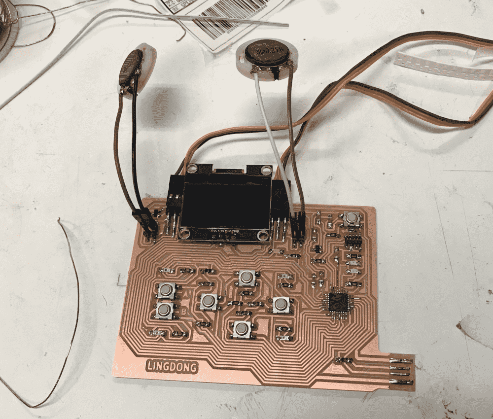
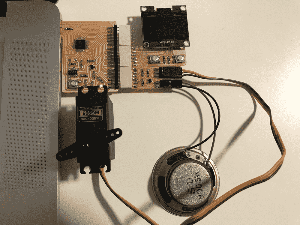
After finishing soldering (there were a lot of components so it took some time, I didn't find anything difficult), I hooked up my servos and speakers. Looks pretty cool!
Getting it to work
Without much trouble I quickly flashed my board with a bootloader. However, I noticed that my board was getting hot when the speakers were plugged in. Perhaps they were not correctly soldered, I thought. I just soldered two jumper wires onto what appeared to be pads on these little janky-looking things in a drawer labelled “speakers” I found somewhere in the shop.
So I asked a question “How to connect speakers” on our section's issue tracker. It turned out people were more concerned with my circuit design than the soldering. TA Andres pointed out that the capacitor between the microcontroller pin and the mosfet was redundant, and it could be useful to connect a resistor in series with the speaker, for the speaker I had have low impedance. Prof. Neil recommended starting with a resistive load and check what it was doing on an oscilloscope.
Sounded like I needed to do some editing to my board, so I decided to figure out the OLED first.
The OLED uses the I2C protocol for receiving commands from the microcontroller. This was the first time I heard about this technology. So, before designing my board, I read prof. Neil's C code on the course website, and figured that I2C basically involved turning on and off two pins repeatedly in quick succession. Sounded straightforward. Therefore, when I designed the board, I just connected two arbitrary pins to the SDA and SCL on the OLED.
So now I found myself franticly searching for why the Arduino Wire library (which I also didn't know before until I searched for how to do I2C in Arduino IDE) didn't let me change the pins used for I2C.
I finally came to the realization that there were dedicated I2C pins on the microcontroller. I needed to read the datasheet to figure out which.
Then I also realized for the first time, that pins, unlike men, are not created equal. Many of them have specialized functions. I suppose that this must have been obvious for my classmates, most of whom had prior experience with Arduino. I am amazed by my obtusity.
There's about 10% chance that two random consecutive pins happen to be the SDA and SCL ones (there're two pairs on SAMD21E). I always find myself to be lucky in these kinds of situations, but I guess this time I was not that lucky.
Then I figured that it must be possible to do I2C in the software, for prof. Neil's code seemed to be doing that. Afterall, it's just turning pins on and off, no? Again searching the internet I discovered the SoftWire libary for Arduino, which seemed to be exactly what I needed.
After some fair amount of troubleshooting (and guesswork) with the library, I got the OLED to display the hello world font from Neil's demo. Yay!
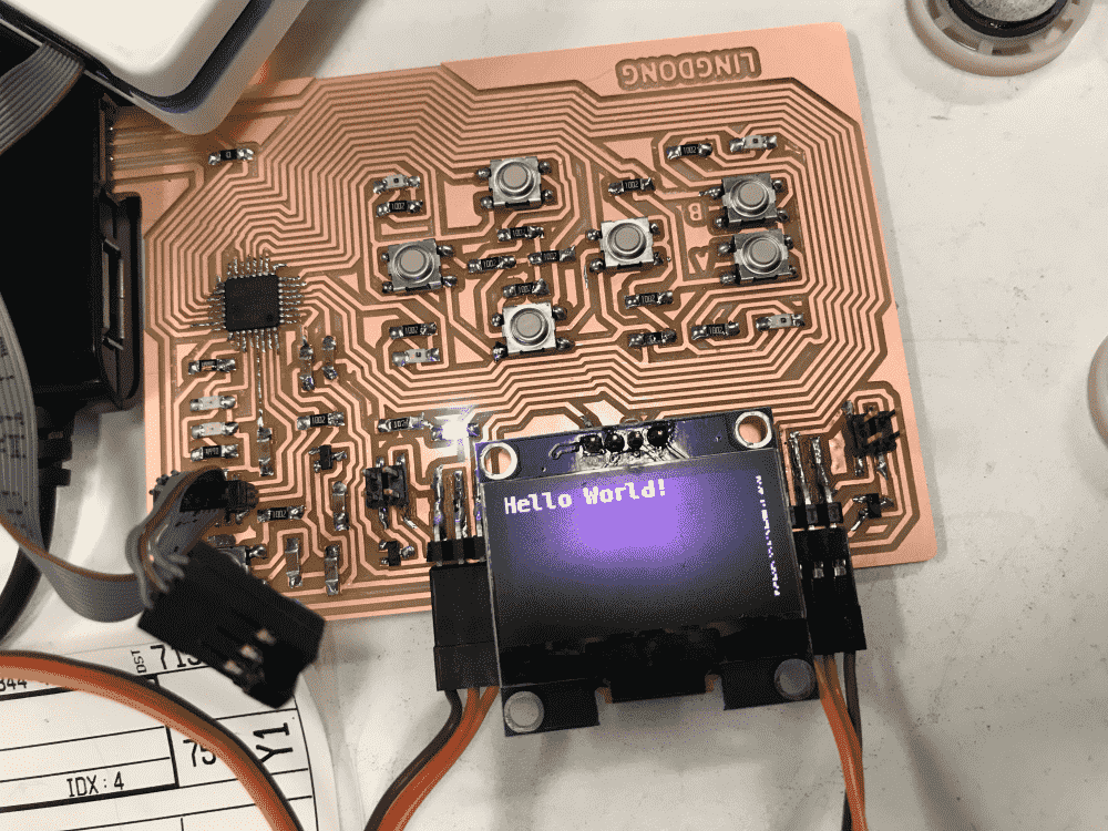
There was some ugly debris on the right edge of the display. But I decided to call it a day and figure out that, and the speakers and the servos, on the next day. I've went from not having the faintest idea about what an I2C is (or an OLED, or the SDA/SCL pins, or the Wire/SoftWire libraries), to being able to display some text with them, by fiddling with some code for an hour or so. So I wanted to pat myself on the back and have some rest first.
Getting it to work, Part II
So it was the next morning and TA Andres came to help me with the speakers. He said that he dreamt about speakers the previous night, and asked if I was able to make any progress. I was ashamed because I neither dreamt about speakers nor made any progress.
After fixing a minor solder bridge on one of the header pins, we still couldn't get the speakers to work, and we seemed to have fried one of them in the process. Andres wired a resistor to one of the speaker's legs to increase impedance. At some point we heard some minor ticks, but no “real” sound was made. To debug, Andres then attached a DC motor in place of the speaker. The motor correctly spun in alternating directions when I emulated PWM in the software.
Therefore, Andres got me another type of speaker, which was larger (and looked less janky). This time, a deafening sound is heard all across the room. Yay!
On the software side, we first tried to do the PWM with Arduino's built-in tone() function, which did nothing. Since I did software I2C, why not software PWM? So I slapped together this code:
void soft_tone(int pin,float freq){
  float wait = 1.0/freq/2.0 * 1000.0 * 1000.0;
  digitalWrite(pin,HIGH);
  delayMicroseconds(wait);
  digitalWrite(pin,LOW);
  delayMicroseconds(wait);
}
Which worked quite nicely.
Soon I got the servo motor to work too, with some similar software PWM. Finally all three output devices are working, sorta. Below is a video demo of them:
Getting it to work, Part III
However, there was a more emergent problem. First of all, my board from time to time forgot that it had a bootloader. Meaning that, when I plugged and unplugged it, it often got bricked, and I needed to edbg a new bootloader onto it again to bring it back. That was an annoyance I bore with so far, by sitting next to an Atmel-ICE.
But then the issue worsened. One time it was so bricked that it took me some ten minutes to bring it back. Then I discovered that my board now had acquired a more serious malady.
The issue was detailed in my post Mysterious Chance-based Board Failure Sometimes Alleviated by Unpowered Atmel-ICE on our sections issue tracker. An extract:
When I plug my board (SAMD21E) into USB hub, there's a 90%+ chance it won't work (the program I uploaded from Arduino IDE is apparently not executed). I can confirm that it has 5V power, and that the Microcontroller is getting 3V3 (using multimeter, my board also has a LED indicator directly connecting 3V3 to GND, which lights up)
If I plug the Atmel-ICE to the JTAG header on my board, the chance of success is greatly increased to around 80%. The Atmel-ICE does NOT have to be powered. Only the ribbon cable needs to be connected to my board.
If I only plug in the ribbon cable, without the Atmel-ICE connected on the other end, it will not work.
If I plug a DIY freeDAP programmer instead of the Atmel-ICE, the chance of success is mildly increased, but is not as effective as the real Atmel-ICE. This is very strange, since the programmer does not need to be powered. It is as if my board needs a “pacifier” like a baby.
TA Anthony was very helpful and suggested a couple of potential issues and solutions (and later prof. Neil chimed in too), such as disjointed ground in my design (which seemed to be not the case), adding a capacitor between reset and ground (which didn't seem to help), etc. My problem remained unsolved.
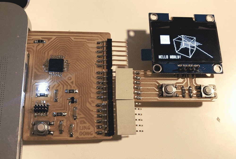
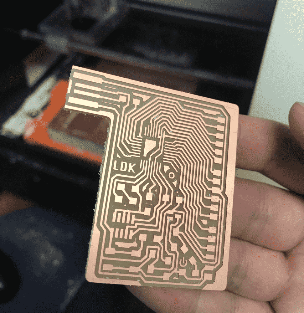
Disheartened I decided to put aside this board for a while. What I really wanted to do that day was some cool graphics with the OLED, but this faulty board was getting in the way. So I fished out a breakout board I made last week, and fabricated a OLED “module” to attach to it. This way I could unstuck myself from the mysterious hardware error and get my software development started.
The OLED on a breakout board
I made this breakout board the previous week, but I had a serious negligence, (or rather, lack of precognitive abilities), for I only had the outgoing pins for 3.3V but none for 5V. This week, I learned that many devices require 5V power.
Luckily, the OLED is not one of those devices, and can happily operate at 3.3V. So quickly I milled a tiny board with two buttons and an OLED, which I then attached to the breakout board.
When I attached the OLED piece to the breakout and uploaded a program, the breakout, which had been working pretty nicely previously, started misbehaving too, not unlike how my big board was failing.
So naturally I suspected the OLED to be the culprit of all my failures. I desoldered it from my big board. However, my big board was still failing in the same way. The OLED was innocent!
It turned out that the issues with my breakout board was different. It appeared that at some point I uploaded a program so buggy that the microcontroller lost its mind. When I re-bootload it with edbg, the program seems to be not completely erased, and some memento fragments from previous buggy program were still executing (LED lights up). So every time I plugged/programmed it, it had strange unpredictable behavior. In the end I added -e option to edbg to give it more thorough lobotomization, and uploaded a less buggy program, which fixed the board.
Finally time for some CG action!
After reading the SSD 1306 datasheet and Neil's demo, I got a hang of the OLED commands. I then slapped together a 3x7 font, a line and triangle rasterizer, and some 3D transformation/projection code.
I drew the font as ASCII art, and used 10 lines of python to generate the C data for it, listed below:
data = [[1 if y==';' else 0 for y in list(x)] for x in """
 ;  ; ; ; ;  ;    ;  ;   ;    ; ;   ; ;                   ;  ;   ;   ;   ;    ; ;;;  ;  ;;;  ;   ;                       ;   ;; ;;; ;;   ;  ;;  ;;; ;;;  ;  ; ; ;;;   ; ; ; ;   ; ; ;;; ;;; ;;   ;  ;;   ;  ;;; ; ; ; ; ; ; ; ; ; ; ;;; ;;; ;   ;;;  ;      ;
 ;  ; ; ; ; ;;; ; ; ;;;  ;   ;   ;  ;;;  ;                ; ; ; ;;  ; ; ; ; ; ; ;   ; ;   ; ; ; ; ;           ;     ;   ; ; ; ; ; ; ; ; ; ; ; ; ;   ;   ; ; ; ;  ;    ; ; ; ;   ;;; ; ; ; ; ; ; ; ; ; ; ; ;  ;  ; ; ; ; ; ; ; ; ; ;   ; ;   ;     ; ; ;      ;
 ;      ;;; ;     ; ;       ;     ;  ;   ;               ;  ; ;  ;    ;   ; ; ; ;   ;     ; ; ; ; ;  ;   ;   ;  ;;;  ;    ; ; ; ;;; ; ; ;   ; ; ;   ;   ;   ; ;  ;    ; ; ; ;   ;;; ; ; ; ; ; ; ; ; ; ; ;    ;  ; ; ; ; ; ; ; ; ; ;   ; ;    ;    ;
 ;      ; ;  ;   ;  ;;;     ;     ; ;;; ;;;     ;;;      ;  ; ;  ;    ;  ;  ; ; ;;; ;;   ;   ;   ;;         ;         ;  ;  ; ; ; ; ;;  ;   ; ; ;;  ;;; ; ; ;;;  ;    ; ;;  ;   ;;; ; ; ; ; ;;  ; ; ;;   ;   ;  ; ; ; ; ;;;  ;   ;   ;  ;    ;    ;
 ;      ;;;   ; ;   ;       ;     ;  ;   ;               ;  ; ;  ;   ;    ; ;;;   ; ; ;  ;  ; ;   ;  ;   ;   ;  ;;;  ;   ;  ; ; ; ; ; ; ;   ; ; ;   ;   ; ; ; ;  ;    ; ; ; ;   ;;; ; ; ; ; ;   ;;; ; ;   ;  ;  ; ; ; ; ;;; ; ;  ;  ;   ;    ;    ;
        ; ; ;;; ; ; ;;;      ;   ;  ;;;  ;  ;;      ;;  ;   ; ;  ;  ;   ; ;   ; ; ; ; ;  ;  ; ; ; ;     ;     ;     ;       ;   ; ; ; ; ; ; ; ; ;   ;   ; ; ; ;  ;  ; ; ; ; ;   ;;; ; ; ; ; ;   ; ; ; ; ; ;  ;  ; ;  ;  ;;; ; ;  ;  ;   ;     ;   ;
 ;      ; ;  ;  ; ;  ;        ; ;   ; ;      ;      ;;  ;    ;  ;;; ;;;  ;    ;  ;   ;   ;   ;   ;                       ;  ;;; ; ; ;;   ;  ;;  ;;; ;    ;  ; ; ;;;  ;  ; ; ;;; ; ; ; ; ;;; ;    ;; ; ;  ;   ;  ;;;  ;  ; ; ; ;  ;  ;;; ;;;   ; ;;;     ;;;
""".split('\n') if len(x)]


arr = [];
for j in range(0,len(data[0])):
  if (j+1) % 4 == 0:
    continue
  a = 0
  for i in range(len(data)):
    a = (a << 1) | data[i][j]
  arr.append(a)

print(arr)
This tiny font allows fitting 256 characters to the screen, almost enough for a tweet! I was lazy and left out the lower-case characters though. So it's just capitals, numbers and symbols.
The line and triangle renderers were quite trivial, since I was quite into these low-level graphics stuff, I've even made a dedicated C library for 1 bit graphics once, though it was one of my least popular projects.
OLED Tips & Tricks
While I was having all the fun drawing complicated 3D stuff on the tiny OLED screen, my classmate Reina asked me why her OLED was not working at all. Turned out there were 2 issues: one was that the screen she got was actually defected, the second was that the Adafruit SSD1306 library she used was incompatible with the particular screens we had at the shop. So we replaced the screen and tried using my code (which didn't use an OLED library and sent the raw command bytes to the device directly). It worked. But Reina found my code too low-level and unreadable. So I patched up the Adafruit library by replacing its failing codes with my own implementation. Now there's a friendly interface and a working implementation, nice.
I then realized that there're so many pitfalls and quirks with the OLED that it took me considerable amount of time to figure out. So I posted a documentation of OLED tips and tricks on the class's issue tracker, in case it might be useful for others.
You can download a PDF of that document here.
The demo Arduino projects mentioned in the document can be downloaded here:
The patch to the Adafruit library can be downloaded here:
- Adafruit_SSD1306.cpp (rename and replace in the library folder, see document)
Getting it to work, Part III
Now that I've taken a nice break from the mysterious frustration and had some relaxing fun with 1 bit graphics, I wanted to return to the problem and fix it.
First, I suspected that the SAMD21E microcontroller might be faulty. Maybe I fried it the same time I fried the speaker. Reina who've done it before helped me desolder it and solder on a new one. The trick for re-soldering was to heat the board with its leftover traces, and place the component on it. The component would then be quite stuck already, and one only need to apply some more solder to top it off.
However, it turned out that the SAMD21E was innocent too. The board still failed exactly the same way. I needed to start using my brain and figure out what was wrong.
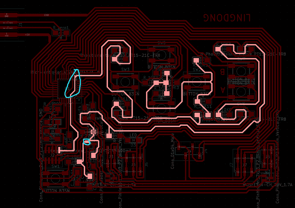
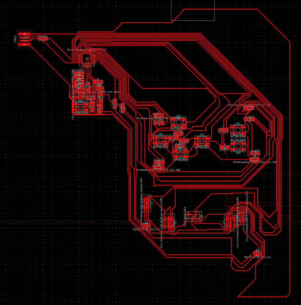
In a sudden moment of enlightenment I wondered if it could be possible that my ground and 3.3V lines are too long. As you can see in the above picture, the 3.3V line took a round trip all over the board before finally reaching the microcontroller. Maybe the microcontroller was not getting its juice in time!
To verify my hypothesis, I soldered two pieces of solder to make shortcuts for the lines.
And guess what? My board was now working perfectly, just as perfectly as my every other board.
Lesson learned:
- Don't have too much fun designing the layout.
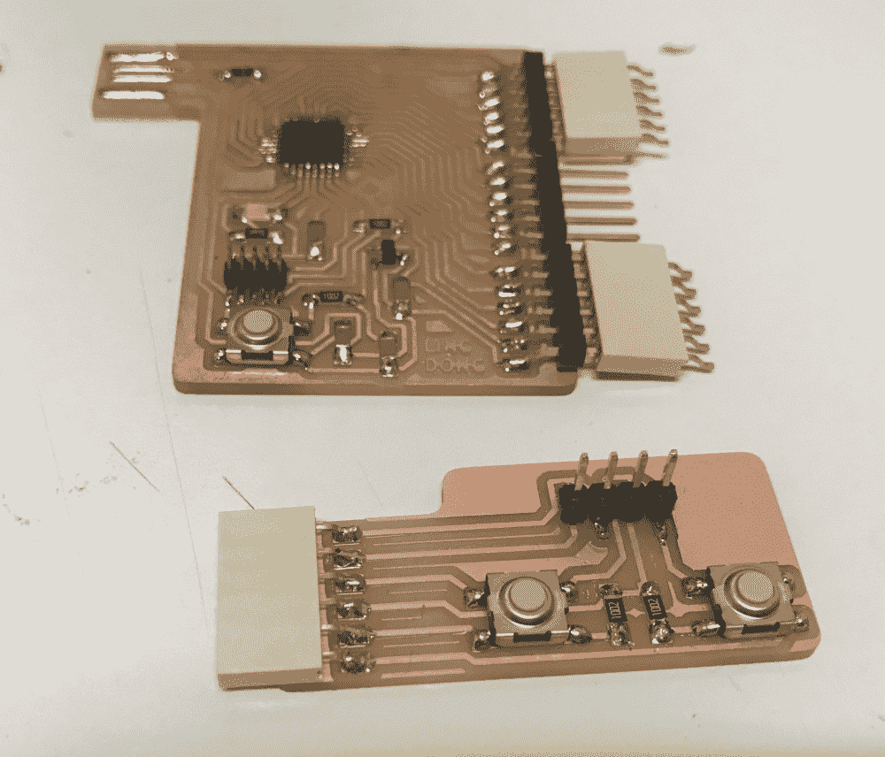
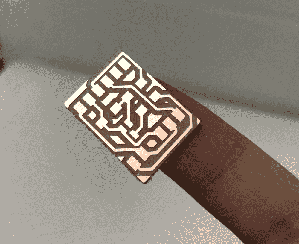
New breakout
Even though my big board was working, I became disillusioned with all-in-one boards. Instead, I fabricated version 2.0 of my breakout board, which now includes a 5V pin, and another tiny module for connecting the servo and the speaker.
Taking TA Zach's advice, I made a new mosfet speaker design, including a resistor connected in series to the speaker: this way the sound would be less deafening.
Demos
The first is a 1 bit graphics demo package. You can select one out of 6 demos from the menu and view cool 2D and 3D stuff.
Code:
//#define SOFTWARE_I2C
#define HARDWARE_I2C_USE_PA0809

#define I2C_ADDRESS 0x3C

#ifdef SOFTWARE_I2C
  #define SDA_PIN 8
  #define SCL_PIN 9
  #include <SoftWire.h>
  SoftWire WIRE(SDA_PIN, SCL_PIN);
  #define I2C_BUFFER_SIZE 129
  char ibuffer[I2C_BUFFER_SIZE];
#else
  #include <Wire.h>
  #ifdef HARDWARE_I2C_USE_PA0809
    TwoWire WIRE(&PERIPH_WIRE1,PIN_WIRE1_SDA, PIN_WIRE1_SCL);
  #else
    #define WIRE Wire
  #endif
  #define I2C_BUFFER_SIZE 32
#endif


#define MAT_IDEN {1,0,0,0, 0,1,0,0, 0,0,1,0, 0,0,0,1}
#define MAT_ROTX(a) {1,0,0,0, 0,cos(a),-sin(a),0, 0,sin(a),cos(a),0, 0,0,0,1}
#define MAT_ROTY(a) {cos(a),0,sin(a),0, 0,1,0,0, -sin(a),0,cos(a),0, 0,0,0,1}
#define MAT_ROTZ(a) {cos(a),-sin(a),0,0, sin(a),cos(a),0,0, 0,0,1,0, 0,0,0,1}
#define MAT_ROAX(x,y,z,th)  {cos(th)+(x)*(x)*cos(th),(x)*(y)*(1-cos(th))-(z)*sin(th),(x)*(z)*(1-cos(th))+(y)*sin(th),0,(y)*(x)*(1-cos(th))+(z)*sin(th),cos(th)+(y)*(y)*(1-cos(th)),(y)*(z)*(1-cos(th))-(x)*sin(th),0,(z)*(x)*(1-cos(th))-(y)*sin(th),(z)*(y)*(1-cos(th))+(x)*sin(th),cos(th)+(z)*(z)*(1-cos(th)),0,0,0,0,1}
#define MAT_TRSL(x,y,z) {1,0,0,x, 0,1,0,y, 0,0,1,z, 0,0,0,1}
#define MAT_SCAL(x,y,z) {x,0,0,0, 0,y,0,0, 0,0,z,0, 0,0,0,1}
#define MAT_MULT(A,B) {(A)[0]*(B)[0]+(A)[1]*(B)[4]+(A)[2]*(B)[8]+(A)[3]*(B)[12],(A)[0]*(B)[1]+(A)[1]*(B)[5]+(A)[2]*(B)[9]+(A)[3]*(B)[13],(A)[0]*(B)[2]+(A)[1]*(B)[6]+(A)[2]*(B)[10]+(A)[3]*(B)[14],(A)[0]*(B)[3]+(A)[1]*(B)[7]+(A)[2]*(B)[11]+(A)[3]*(B)[15],(A)[4]*(B)[0]+(A)[5]*(B)[4]+(A)[6]*(B)[8]+(A)[7]*(B)[12],(A)[4]*(B)[1]+(A)[5]*(B)[5]+(A)[6]*(B)[9]+(A)[7]*(B)[13],(A)[4]*(B)[2]+(A)[5]*(B)[6]+(A)[6]*(B)[10]+(A)[7]*(B)[14],(A)[4]*(B)[3]+(A)[5]*(B)[7]+(A)[6]*(B)[11]+(A)[7]*(B)[15],(A)[8]*(B)[0]+(A)[9]*(B)[4]+(A)[10]*(B)[8]+(A)[11]*(B)[12],(A)[8]*(B)[1]+(A)[9]*(B)[5]+(A)[10]*(B)[9]+(A)[11]*(B)[13],(A)[8]*(B)[2]+(A)[9]*(B)[6]+(A)[10]*(B)[10]+(A)[11]*(B)[14],(A)[8]*(B)[3]+(A)[9]*(B)[7]+(A)[10]*(B)[11]+(A)[11]*(B)[15],(A)[12]*(B)[0]+(A)[13]*(B)[4]+(A)[14]*(B)[8]+(A)[15]*(B)[12],(A)[12]*(B)[1]+(A)[13]*(B)[5]+(A)[14]*(B)[9]+(A)[15]*(B)[13],(A)[12]*(B)[2]+(A)[13]*(B)[6]+(A)[14]*(B)[10]+(A)[15]*(B)[14],(A)[12]*(B)[3]+(A)[13]*(B)[7]+(A)[14]*(B)[11]+(A)[15]*(B)[15]}
#define MAT_TFRM(A,v) {((A)[0]*(v)[0]+(A)[1]*(v)[1]+(A)[2]*(v)[2]+(A)[3])/((A)[12]*(v)[0]+(A)[13]*(v)[1]+(A)[14]*(v)[2]+(A)[15]),((A)[4]*(v)[0]+(A)[5]*(v)[1]+(A)[6]*(v)[2]+(A)[7])/((A)[12]*(v)[0]+(A)[13]*(v)[1]+(A)[14]*(v)[2]+(A)[15]),((A)[8]*(v)[0]+(A)[9]*(v)[1]+(A)[10]*(v)[2]+(A)[11])/((A)[12]*(v)[0]+(A)[13]*(v)[1]+(A)[14]*(v)[2]+(A)[15])}
#define MAT_PROJ(f,v) {(f)*(v)[0]/(v)[2],(f)*(v)[1]/(v)[2]}

#define BARY_DET(x,y,x1,y1,x2,y2,x3,y3) (((y2)-(y3))*((x1)-(x3))+((x3)-(x2))*((y1)-(y3)))
#define BARY_U(x,y,x1,y1,x2,y2,x3,y3)   (((y2)-(y3))*((x)-(x3))+((x3)-(x2))*((y)-(y3)))
#define BARY_V(x,y,x1,y1,x2,y2,x3,y3)   (((y3)-(y1))*((x)-(x3))+((x1)-(x3))*((y)-(y3)))


int BTN_CURR[2] = {HIGH,HIGH};
int BTN_PREV[2] = {HIGH,HIGH};
const int BTNS[2] = {6,7};

static const uint8_t FONT[] = {0,0,0,0,125,0,96,0,96,127,20,127,50,107,38,39,8,115,62,107,42,0,96,0,28,34,65,65,34,28,107,62,107,8,62,8,2,3,0,8,8,8,3,3,0,3,28,96,62,65,62,33,127,1,35,69,57,34,73,54,60,4,127,122,73,78,62,73,38,64,79,112,54,73,54,50,73,62,0,20,0,2,20,0,8,20,34,20,20,20,34,20,8,32,77,48,63,65,125,127,80,127,127,73,54,62,65,34,127,65,62,127,73,65,127,72,72,62,65,46,127,8,127,65,127,65,2,1,126,127,8,119,127,1,1,127,62,127,127,64,127,127,65,127,127,72,48,62,69,63,127,72,55,50,73,38,64,127,64,127,1,127,124,3,124,127,14,127,119,8,119,112,15,112,71,73,113,127,65,65,96,28,3,65,65,127,32,64,32,1,1,1,64,32,0};

uint8_t OLED_BUFF[1024] = {0};
uint8_t OLED_DIRT[1024] = {0};

void OLEDcommand(uint8_t c) {
  WIRE.beginTransmission(I2C_ADDRESS);
  static uint8_t data[2];
  data[0] = 0;
  data[1] = c;
  WIRE.write(data,2);
  WIRE.endTransmission();
}

void OLEDcommands(uint8_t c1,uint8_t c2) {
  WIRE.beginTransmission(I2C_ADDRESS);
  static uint8_t data[3];
  data[0] = 0;
  data[1] = c1;
  data[2] = c2;
  WIRE.write(data,3);
  WIRE.endTransmission();
}
void OLEDdata(uint8_t d) {
   WIRE.beginTransmission(I2C_ADDRESS);
   static uint8_t data[2];
   data[0] = 0x40;
   data[1] = d;
   WIRE.write(data,2);
   WIRE.endTransmission();
}
int OLEDdata_cnt = -1;
void OLEDbegin_data(){
  if (OLEDdata_cnt != -1) return;
  WIRE.beginTransmission(I2C_ADDRESS);
  WIRE.write(0x40);
  OLEDdata_cnt = 0;
}
void OLEDput_data(uint8_t d){
  OLEDdata_cnt++;
  if (OLEDdata_cnt > I2C_BUFFER_SIZE){
    OLEDend_data();
    OLEDbegin_data();
  }
  WIRE.write(d);
}
void OLEDend_data(){
  if (OLEDdata_cnt == -1) return;
  WIRE.endTransmission();
  OLEDdata_cnt = -1;
}


void OLEDrestart(){
  OLEDcommand(0xae); // display off
  OLEDcommands(0xa8,0x3f); // set multiplex ratio, ratio 63
  OLEDcommands(0xd3,0x00); // set display offset, no offset
  OLEDcommand(0x40); // set display start line
  OLEDcommand(0xa0); // set segment remap col 127 to seg 0
  OLEDcommand(0xc8); // set COM output reverse
  OLEDcommands(0xda,0x12); // COM pin config, alt bottom to top
  OLEDcommands(0x81,0xff); // set contrast, max contrast
  OLEDcommand(0xa4); // resume to RAM display
  OLEDcommand(0xa6); // normal non-inverted display
  OLEDcommands(0xd5,0x80); // set clock divider, default
  OLEDcommands(0x8d,0x14); // set charge pump, enable
  OLEDcommands(0x20,0x02); // set memory mode, page addressing
  OLEDcommand(0xaf); // display on

  for (int j = 0; j < 8; ++j) {
    OLEDcommands(0x00,0x9);
    OLEDcommand(0xB0+j);
    for (int i = 0; i < 128; ++i) OLEDdata(0);
    OLEDgoto(j,65);
    for (int i = 0; i < 10; ++i) OLEDdata(0);
  }
  for (int i = 0; i < 1024; i++){
    OLED_BUFF[i] = 0;
    OLED_DIRT[i] = 0;
  }
}

void OLEDgoto(uint8_t row,uint8_t col){
  OLEDcommands(0x00+(col & 0x0F),0x10+((col >> 4) & 0x0F));
  OLEDcommand(0xB0+row);
}

void OLEDpixel(int x, int y){
  if (x < 0 || x >= 128) return;
  if (y < 0 || y >= 64 ) return;
  y = 63-y;
  int row = y / 8;
  OLED_DIRT[ row * 128 + x] |= (1 << (y % 8));
}

void OLEDunpixel(int x, int y){
  if (x < 0 || x >= 128) return;
  if (y < 0 || y >= 64 ) return;
  y = 63-y;
  int row = y / 8;
  OLED_DIRT[ row * 128 + x] &= ~(1 << (y % 8));
}

bool OLEDpeak(int x, int y){
  if (x < 0 || x >= 128) return false;
  if (y < 0 || y >= 64 ) return false;
  y = 63-y;
  int row = y / 8;
  return OLED_DIRT[ row * 128 + x] & (1 << (y % 8));
}


void OLEDclear(){
  for (int i = 0; i < 1024; i++){
    OLED_DIRT[i] = 0;
  }
}


void OLEDflush(){
  for (int i = 0; i < 8; i++){
    int j0 = -1;
    for (int j = 0; j < 128; j++){
      int idx = i*128+j;
      uint8_t d = OLED_DIRT[idx];
      if (d != OLED_BUFF[idx]){
        if (j0 == -1){
          j0 = j;
          OLEDend_data();
          OLEDgoto(i,j);
          OLEDbegin_data();
        }
//        OLEDdata(d);
        OLEDput_data(d);
        OLED_BUFF[idx] = d;
      }else{
        OLEDend_data();
        j0 = -1;
      }
    }
  }
  OLEDend_data();
}


void OLED3x7string_direct(uint8_t row,uint8_t col,char str[]) {
  static uint8_t index,offset,pointer;
  static char chr;
  OLEDgoto(row,col);
  index = 0;
  while (1) {
     chr = str[index];
     if (chr == '\0')
       break;
     pointer = chr-' ';
     for (offset = 0; offset < 3; ++offset) {
       OLEDdata(FONT[3*pointer+offset]);
     }
     OLEDdata(0);
     ++index;
   }
}


void OLED3x7string(uint8_t row,uint8_t col,char str[]) {
  static uint8_t index,offset,pointer;
  static char chr;
  int rc = row*128+col;
  index = 0;
  while (1) {
     chr = str[index];
     if (chr == '\0')
       break;
     pointer = chr-' ';
     for (offset = 0; offset < 3; ++offset) {
       OLED_DIRT[rc+index*4+offset] = FONT[3*pointer+offset];
     }
     ++index;
   }
}

void OLEDfillrect(int x, int y, int w, int h){
   for (int i = y; i < y+h; i++){
     for (int j = x; j < x+w; j++){
       OLEDpixel(j,i);
     }
   }
}


#define LINE_STEP(sx0,sx1,sy0,sy1,x) (((sx0) == (sx1)) ? (sy1) : ((int)round((float)(sy0)+(float)((x)-(sx0))*(float)((sy1)-(sy0))/(float)((sx1)-(sx0)))) )

void OLEDline(float x0 ,float y0 ,float x1 ,float y1){
  int sx0 = (int)round(x0);
  int sy0 = (int)round(y0);
  int sx1 = (int)round(x1);
  int sy1 = (int)round(y1);
  int dx  = sx1 > sx0 ? 1 : -1; // x increment
  int dy  = sy1 > sy0 ? 1 : -1; // y increment
  if (abs(sx0 - sx1) >= abs(sy0 - sy1)){ // slope < 1 ?
    int x = sx0;
    while (x != sx1+dx){
      int y = LINE_STEP(sx0,sx1,sy0,sy1,x);
      OLEDpixel(x,y);
      x += dx;
    }
  }else{
    int y = sy0;
    while (y != sy1+dy){
      int x = LINE_STEP(sy0,sy1,sx0,sx1,y);
      OLEDpixel(x,y);
      y += dy;
    }
  }
}

#define PT_IN_PL(x,y,x0,y0,x1,y1) ((((x)-(x0))*((y1)-(y0)) - ((y)-(y0))*((x1)-(x0)))<=0)
#define PT_IN_TRI(x,y,x0,y0,x1,y1,x2,y2) ( PT_IN_PL(x,y,x0,y0,x1,y1) && PT_IN_PL(x,y,x1,y1,x2,y2) && PT_IN_PL(x,y,x2,y2,x0,y0) )

void OLEDtriangle(float x0 ,float y0 ,float x1 ,float y1 ,float x2 ,float y2, char* pttn, int pttn_w, int pttn_h){
  if (!PT_IN_PL(x0,y0,x1,y1,x2,y2)){
    float x_tmp = x1;
    float y_tmp = y1;
    x1 = x2;
    y1 = y2;
    x2 = x_tmp;
    y2 = y_tmp;
  }
  int xmin = (int)floor(fmin(fmin(x0,x1),x2));
  int xmax = (int) ceil(fmax(fmax(x0,x1),x2));
  int ymin = (int)floor(fmin(fmin(y0,y1),y2));
  int ymax = (int) ceil(fmax(fmax(y0,y1),y2));

  int y; for (y=ymin; y <= ymax; y++){
    int x; for (x=xmin; x <= xmax; x++){

      if (PT_IN_TRI((float)x,(float)y,x0,y0,x1,y1,x2,y2)){
        bool v = '1' ==pttn[(y % pttn_h) * pttn_w + (x % pttn_w)];
        if (v) {
          OLEDpixel(x,y);
        }else{
          OLEDunpixel(x,y);
        }
      }
    }
  }
}


#define MAKE_3D_MATRIX \
  float scl[]  = MAT_SCAL(sx,sy,sz); \
  float rotx[] = MAT_ROTX(rx); \
  float roty[] = MAT_ROTY(ry); \
  float rotz[] = MAT_ROTZ(rz); \
  float rot0[]= MAT_MULT(roty,rotz); \
  float rot[]  = MAT_MULT(rotx,rot0); \
  float sclrot[] = MAT_MULT(rot,scl); \
  float trl[]  = MAT_TRSL(dx,dy,dz); \
  float tfm[]  = MAT_MULT(trl,sclrot);

void OLEDwireframe(float* xyzs,uint16_t* edges,int n_edges,
  float sx, float sy, float sz,
  float rx, float ry, float rz,
  float dx, float dy, float dz,
  float focal,float ox, float oy
){
  MAKE_3D_MATRIX

  for (int i = 0; i < n_edges; i++){
    float v0[3] = {xyzs[edges[i*2+0]*3+0],xyzs[edges[i*2+0]*3+1],xyzs[edges[i*2+0]*3+2]};
    float v1[3] = {xyzs[edges[i*2+1]*3+0],xyzs[edges[i*2+1]*3+1],xyzs[edges[i*2+1]*3+2]};
    float u0[] = MAT_TFRM(tfm,v0);
    float u1[] = MAT_TFRM(tfm,v1);
    float p0[] = MAT_PROJ(focal,u0);
    float p1[] = MAT_PROJ(focal,u1);
    OLEDline(ox+p0[0], oy-p0[1], ox+p1[0], oy-p1[1]);
  }
}


void OLEDflatshade(float* xyzs,uint16_t* trigs,int n_trigs,
  float sx, float sy, float sz,
  float rx, float ry, float rz,
  float dx, float dy, float dz,
  float focal,float ox, float oy,
  char* pttn, int pttn_w, int pttn_h
){
  MAKE_3D_MATRIX

  for (int i = 0; i < n_trigs; i++){
    float v0[3] = {xyzs[trigs[i*3+0]*3+0],xyzs[trigs[i*3+0]*3+1],xyzs[trigs[i*3+0]*3+2]};
    float v1[3] = {xyzs[trigs[i*3+1]*3+0],xyzs[trigs[i*3+1]*3+1],xyzs[trigs[i*3+1]*3+2]};
    float v2[3] = {xyzs[trigs[i*3+2]*3+0],xyzs[trigs[i*3+2]*3+1],xyzs[trigs[i*3+2]*3+2]};

    float u0[] = MAT_TFRM(tfm,v0);
    float u1[] = MAT_TFRM(tfm,v1);
    float u2[] = MAT_TFRM(tfm,v2);
    float p0[] = MAT_PROJ(focal,u0);
    float p1[] = MAT_PROJ(focal,u1);
    float p2[] = MAT_PROJ(focal,u2);

    OLEDtriangle(ox+p0[0], oy-p0[1], ox+p1[0], oy-p1[1], ox+p2[0], oy-p2[1], pttn, pttn_w, pttn_h);
  }
}


#define TPOT_PROC3D(N) float k ## N[] = MAT_TFRM(tfm,p ## N); float q ## N[] = MAT_PROJ(focal,k ## N);

void teapot(
  float sx, float sy, float sz,
  float rx, float ry, float rz,
  float dx, float dy, float dz,
  float focal
){

  OLEDclear();

  MAKE_3D_MATRIX

  float w = 1.0;
  float h = 1.2;
  int n = 10;
  int m = 16;
  for (int i = 0; i < n; i++){
    float t0 = (float)i/(float)(n-1);
    float t1 = (float)min(i+1,n-1)/(float)(n-1);
    float r0 = w*(0.05+0.95*(pow(0.25-pow(t0-0.5,2),0.5)*(2.6+2.4*pow(t0,1.5))*0.542));
    float r1 = w*(0.05+0.95*(pow(0.25-pow(t1-0.5,2),0.5)*(2.6+2.4*pow(t1,1.5))*0.542));
    for (int j = 0; j < m; j++){
      float s0 = (float)j/(float)m;
      float s1 = (float)((j+1)%m)/(float)m;

      float pay = (t0-0.5)*h;
      float pby = (t1-0.5)*h;

      float p0[] = {cos(s0*PI*2)*r0,pay,sin(s0*PI*2)*r0};
      float p1[] = {cos(s1*PI*2)*r0,pay,sin(s1*PI*2)*r0};
      float p2[] = {cos(s0*PI*2)*r1,pby,sin(s0*PI*2)*r1};

      TPOT_PROC3D(0);
      TPOT_PROC3D(1);
      TPOT_PROC3D(2);

      OLEDline(64+q0[0],32+q0[1],64+q1[0],32+q1[1]);
      OLEDline(64+q0[0],32+q0[1],64+q2[0],32+q2[1]);
    }
  }
  int n1 = 7;
  float rm0 = 0.25;
  float rm1 = 0.12;
  float rlx = 0.3;
  float rly = -0.35;
  for (int i = 0; i < n1; i++){
    float t0 = (float)i/(float)n1;
    float t1 = (float)((i+1)%n1)/(float)n1;

    float p0[] = {w-0.2,cos(t0*PI*2)*rm0,sin(t0*PI*2)*rm0};
    float p1[] = {w-0.2,cos(t1*PI*2)*rm0,sin(t1*PI*2)*rm0};
    float p2[] = {w+rlx+cos(t0*PI*2)*rm1,rly,sin(t0*PI*2)*rm1};
    float p3[] = {w+rlx+cos(t1*PI*2)*rm1,rly,sin(t1*PI*2)*rm1};

    TPOT_PROC3D(0);
    TPOT_PROC3D(1);
    TPOT_PROC3D(2);
    TPOT_PROC3D(3);

    OLEDline(64+q0[0],32+q0[1],64+q1[0],32+q1[1]);
    OLEDline(64+q0[0],32+q0[1],64+q2[0],32+q2[1]);
    OLEDline(64+q2[0],32+q2[1],64+q3[0],32+q3[1]);
  }
  float rh = 0.07;
  float crw = 0.3;
  float crh = 0.25;
  float hlx = -0.96;
  float hly = 0;
  int n2 = 10;
  int m2 = 4;
  for (int i = 0; i < n2; i++){
    float t0 = (float)i/(float)(n2-1);
    float t1 = (float)min(i+1,n2-1)/(float)(n2-1);

    float a0 = t0*PI*1.5+PI*0.45;
    float a1 = t1*PI*1.5+PI*0.45;

    float c0[] = { cos(a0) * crw, sin(a0) * crh  };
    float c1[] = { cos(a1) * crw, sin(a1) * crh  };

    float v0[] = { cos(a0)*rh, sin(a0)*rh, 0};
    float v1[] = { cos(a1)*rh, sin(a1)*rh, 0};

    float o0[] = { cos(a0-PI/2), sin(a0-PI/2), 0};
    float o1[] = { cos(a1-PI/2), sin(a1-PI/2), 0};

    for (int j = 0; j < m2; j++){
      float s0 = (float)j/(float)m2;
      float s1 = (float)((j+1)%m2)/(float)m2;

      float m0[] = MAT_ROAX(o0[0],o0[1],o0[2],s0*PI*2);
      float m1[] = MAT_ROAX(o0[0],o0[1],o0[2],s1*PI*2);
      float m2[] = MAT_ROAX(o1[0],o1[1],o1[2],s0*PI*2);

      float u0[] = MAT_TFRM(m0,v0);
      float u1[] = MAT_TFRM(m1,v0);
      float u2[] = MAT_TFRM(m2,v1);

      float p0[] = {c0[0]+u0[0]+hlx,c0[1]+u0[1]+hly,u0[2]};
      float p1[] = {c0[0]+u1[0]+hlx,c0[1]+u1[1]+hly,u1[2]};
      float p2[] = {c1[0]+u2[0]+hlx,c1[1]+u2[1]+hly,u2[2]};

      TPOT_PROC3D(0);
      TPOT_PROC3D(1);
      TPOT_PROC3D(2);

      OLEDline(64+q0[0],32+q0[1],64+q1[0],32+q1[1]);
      OLEDline(64+q0[0],32+q0[1],64+q2[0],32+q2[1]);
    }
  }
  int n3 = 6;
  float r3 = 0.2;
  float h3 = 0.1;
  for (int i = 0; i < n3; i++){
    float t0 = (float)i/(float)n3;
    float t1 = (float)((i+1)%n1)/(float)n3;

    float p0[] = {cos(t0*PI*2)*r3,-h/2-h3,sin(t0*PI*2)*r3};
    float p1[] = {cos(t1*PI*2)*r3,-h/2-h3,sin(t1*PI*2)*r3};
    float p2[] = {0,-h/2+0.05,0};

    TPOT_PROC3D(0);
    TPOT_PROC3D(1);
    TPOT_PROC3D(2);

    OLEDline(64+q0[0],32+q0[1],64+q1[0],32+q1[1]);
    OLEDline(64+q0[0],32+q0[1],64+q2[0],32+q2[1]);

  }

//  OLED3x7string(7,3,"TEAPOT");
  OLEDflush();
}


void terrain(
  float* data, int w, int h,
  float sx, float sy, float sz,
  float rx, float ry, float rz,
  float dx, float dy, float dz,
  float focal
){
  OLEDclear();

  MAKE_3D_MATRIX

  for (int i = 0; i < h-1; i++){
    for (int j = 0; j < w-1; j++){
      float p0[] = {(float)(j+0.5)/(float)w-0.5, data[i*w+j],     (float)(i+0.5)/(float)h-0.5};
      float p1[] = {(float)(j+1.5)/(float)w-0.5, data[i*w+j+1],   (float)(i+0.5)/(float)h-0.5};
      float p2[] = {(float)(j+0.5)/(float)w-0.5, data[i*w+j+w],   (float)(i+1.5)/(float)h-0.5};
      float p3[] = {(float)(j+1.5)/(float)w-0.5, data[i*w+j+w+1], (float)(i+1.5)/(float)h-0.5};

      TPOT_PROC3D(0);
      TPOT_PROC3D(1);
      TPOT_PROC3D(2);
      TPOT_PROC3D(3);

      OLEDtriangle(
        q0[0]+64,q0[1]+32,
        q1[0]+64,q1[1]+32,
        q3[0]+64,q3[1]+32,
        "1000",2,2
      );
      OLEDtriangle(
        q0[0]+64,q0[1]+32,
        q3[0]+64,q3[1]+32,
        q2[0]+64,q2[1]+32,
        "1000",2,2
      );
    }
  }
  for (int i = 0; i < h-1; i++){
    for (int j = 0; j < w-1; j++){
      float p0[] = {(float)(j+0.5)/(float)w-0.5, data[i*w+j],     (float)(i+0.5)/(float)h-0.5};
      float p1[] = {(float)(j+1.5)/(float)w-0.5, data[i*w+j+1],   (float)(i+0.5)/(float)h-0.5};
      float p2[] = {(float)(j+0.5)/(float)w-0.5, data[i*w+j+w],   (float)(i+1.5)/(float)h-0.5};
      float p3[] = {(float)(j+1.5)/(float)w-0.5, data[i*w+j+w+1], (float)(i+1.5)/(float)h-0.5};

      TPOT_PROC3D(0);
      TPOT_PROC3D(1);
      TPOT_PROC3D(2);
      TPOT_PROC3D(3);

      OLEDline( q0[0]+64,q0[1]+32,  q1[0]+64,q1[1]+32);
      OLEDline( q0[0]+64,q0[1]+32,  q2[0]+64,q2[1]+32);

      if (j == w-2){
        OLEDline( q1[0]+64,q1[1]+32, q3[0]+64,q3[1]+32);
      }
      if (i == h-2){
        OLEDline( q2[0]+64,q2[1]+32,  q3[0]+64,q3[1]+32);
      }
    }
  }

  OLEDflush();

}


void soft_tone(int pin,float freq){
  float wait = 1.0/freq/2.0 * 1000.0 * 1000.0;
  digitalWrite(pin,HIGH);
  delayMicroseconds(wait);
  digitalWrite(pin,LOW);
  delayMicroseconds(wait);
}


void setup() {
  pinMode(2,OUTPUT);

  pinMode(28,OUTPUT);
  for (int i = 0; i < 2; i++) pinMode(BTNS[i], INPUT);
  digitalWrite(28,HIGH);

  #ifdef SOFTWARE_I2C
    WIRE.setDelay_us(1);
    WIRE.enablePullups();
    WIRE.setRxBuffer(ibuffer, I2C_BUFFER_SIZE);
    WIRE.setTxBuffer(ibuffer, I2C_BUFFER_SIZE);
  #endif

  WIRE.begin();
  Serial.begin(9600);


}

int mode = -2;


int frame = 0;

float cube_xyzs[] = {-1,-1,-1, -1,-1,1, -1,1,-1, -1,1,1,
                      1,-1,-1,  1,-1,1,  1,1,-1,  1,1,1};
uint16_t cube_edges[] = {0,1,  2,3,  4,5,  6,7,
                         0,4,  1,5,  2,6,  3,7,
                         0,2,  1,3,  4,6,  5,7};
float plane_xyzs[] = {-1,-1,1,  1,-1,1,  -1,1,1, 1,1,1};
uint16_t plane_trigs[] = {0,1,3,  0,3,2};


/*******************************************************
 * CUBES                                               *
 *******************************************************/

void demo_cubes_init(){
  demo_cubes_draw();
}

void demo_cubes_btn(int idx){
  if (idx){
    frame --;
  }else{
    frame ++;
  }
  demo_cubes_draw();
}

void demo_cubes_draw(){
  OLEDclear();
  for (int i = 0; i < 2; i++){
    for (int j = 0; j < 4; j++){
      float roty =  (0.8 - j/3.0 * 0.6) * PI/2;
      float rotx = - (i*0.05 + frame*0.05);

      OLEDflatshade(plane_xyzs,plane_trigs,2,
        1,1,1,
        rotx,roty,0,
        0,0,11,
        100,
        j*32+16,i*32+16,
        "1000", 2, 2);

      OLEDwireframe(cube_xyzs,cube_edges,12,
        1,1,1,
        rotx,roty,0,
        0,0,11,
        100,
        j*32+16,i*32+16);
    }
  }
  OLEDflush();
}


/*******************************************************
 * TEAPOT                                              *
 *******************************************************/

void demo_teapot_init(){
  demo_teapot_draw();
}

void demo_teapot_btn(int idx){
  if (idx){
    frame --;
  }else{
    frame ++;
  }
  demo_teapot_draw();
}

void demo_teapot_draw(){
  teapot(1,1,1,
    frame*0.02,0+frame*0.1,0,
    0,0,3,
    100
  );
}

/*******************************************************
 * SIERP                                               *
 *******************************************************/
 // (from classic example on TI-84 calculator)
float sierp_x;
float sierp_y;
void demo_sierp_init(){
  sierp_x = (float)rand()/(float)RAND_MAX;
  sierp_y = (float)rand()/(float)RAND_MAX;
  OLEDclear();
  demo_sierp_draw();
}

void demo_sierp_btn(int idx){
  demo_sierp_draw();
}

void demo_sierp_draw(){
  for (int k = 1; k < 300; k++){
    float n = (float)rand()/(float)RAND_MAX;
    if (n <= 1.0/3){
      sierp_x*= 0.5;
      sierp_y*= 0.5;
    }
    if (1.0/3 < n && n <= 2.0/3){
      sierp_x = 0.5 * (0.5 + sierp_x);
      sierp_y = 0.5 * (1 + sierp_y);
    }
    if (2.0/3 < n){
      sierp_x = 0.5 * (1+sierp_x);
      sierp_y = 0.5 * sierp_y;
    }
    OLEDpixel( (int)(4+sierp_x*120) , (int)(62-sierp_y*60)  );
  }
  OLEDflush();
}


/*******************************************************
 * MAZE                                                *
 *******************************************************/
// ported from my old assembly code https://github.com/LingDong-/wasm-fun/blob/master/wat/mazegen.wat

#define MAZE_W 21
#define MAZE_H 10
uint8_t maze_data[MAZE_W*MAZE_H] = {0};
#define MAZE_AT(x,y) maze_data[(y)*MAZE_W+(x)]
#define MAZE_R_HI3(x,y) ((MAZE_AT(x,y) >> 5) & 0x7)
#define MAZE_R_LO5(x,y) ((MAZE_AT(x,y)) & 0x1F)
#define MAZE_X_HI3(x,y) (MAZE_AT(x,y) &= 0x1F)
#define MAZE_W_HI3(x,y,v) (MAZE_AT(x,y) = (MAZE_AT(x,y) & 0x1F) | ((v)<<5))
#define MAZE_ON_BITN(x,y,n) (MAZE_AT(x,y) |= (1<<(n)))


void generate_maze(){
  int x,y,sx,sy,ox,oy,r;

  for (int i = 0; i < MAZE_W*MAZE_H; i++) maze_data[i] = 0;
  MAZE_AT(0,0) = 8;
  sx = 1; sy=0;
  x = sx; y=sy;
  maze_walk_loop:
  ox = x, oy = y;
  do{
    x = ox;
    y = oy;
    r = rand() % 4;
    if (!(r & 1)){
      x = x + (r & 2) - 1;
    }else{
      y = y + (r & 2) - 1;
    }
  }while(x < 0 || y < 0 || x >= MAZE_W || y >= MAZE_H);

  MAZE_W_HI3(ox,oy,r);
  if (MAZE_R_LO5(x,y)){
    ox = x; oy = y;
    x = sx;
    y = sy;
    do{
      r = MAZE_R_HI3(x,y);
      MAZE_ON_BITN(x,y,4);
      if ( !(r & 1)){
        if (!(r & 2)){
          MAZE_ON_BITN(x,y,3);
          x -= 1;
          MAZE_ON_BITN(x,y,0);
        }else{
          MAZE_ON_BITN(x,y,0);
          x += 1;
          MAZE_ON_BITN(x,y,3);
        }
      }else{
        if (!(r & 2 )){
          MAZE_ON_BITN(x,y,1);
          y -= 1;
          MAZE_ON_BITN(x,y,2);
        }else{
          MAZE_ON_BITN(x,y,2);
          y += 1;
          MAZE_ON_BITN(x,y,1);
        }
      }
    } while (x != ox || y != oy);

    sx = -1; sy = -1;
    for (y = 0; y < MAZE_H; y++){
      for (x = 0; x < MAZE_W; x++){
        MAZE_X_HI3(x,y);
        if (sx == -1 && sy == -1 && !MAZE_AT(x,y)){
          sx = x;
          sy = y;
        }
      }
    }
    if (sx == -1 && sy == -1){
    }else{
      x = sx;
      y = sy;
      ox = x;
      oy = y;
      goto maze_walk_loop;
    }
  }else{
    goto maze_walk_loop;
  }

}

void draw_maze(){
//  for (int i = 0; i < MAZE_H; i++){
//    for (int j = 0; j < MAZE_W; j++){
//      int v = MAZE_AT(j,i);
//      if (v & 0b1000){
//        Serial.print(" ");
//      }else{
//        Serial.print("|");
//      }
//      if (v & 0b0100){
//        Serial.print(" ");
//      }else{
//        Serial.print("_");
//      }
//    }
//    Serial.print("\n");
//  }

  for (int i = 0; i < MAZE_H; i++){
    for (int j = 0; j < MAZE_W; j++){
      int v = MAZE_AT(j,i);
      if (! (v & 0b1000)){//left
        for (int k = 0; k < 6; k++){
          OLEDpixel(2+j*6,i*6+k);
        }
      }
      if (! (v & 0b0100)){//down
        for (int k = 0; k < 6; k++){
          OLEDpixel(2+j*6+k,i*6+6);
        }
      }
      if (! (v & 0b0010)){//up
        for (int k = 0; k < 6; k++){
          OLEDpixel(2+j*6+k,i*6);
        }
      }
      if (! (v & 0b0001)){//right
        for (int k = 0; k < 6; k++){
          OLEDpixel(2+j*6+6,i*6+k);
        }
      }
    }
  }
  for (int i = 0; i < MAZE_H*6; i++){
    OLEDpixel(127,i);
  }
}

void draw_dir(float x, float y, int dir){
  float a = 2;
  float b = 1;
  if (dir == 0){
    OLEDtriangle(x-1,y-b, x+a-1,y, x-1,y+b, "1",1,1);
  }else if (dir == 1){
    OLEDtriangle(x,y+a-1, x-b,y-1, x+b,y-1, "1",1,1);
  }else if (dir == 2){
    OLEDtriangle(x-a+1,y, x+1,y-b, x+1,y+b, "1",1,1);
  }else if (dir == 3){
    OLEDtriangle(x,y-a+1, x+b,y+1, x-b,y+1, "1",1,1);

  }
}

int maze_x = 0;
int maze_y = 0;
int maze_d = 0;

void demo_maze_init(){
  srand((int)millis());
  generate_maze();
  maze_data[0] &= ~0b1010;
  demo_maze_draw();
}

void demo_maze_btn(int idx){
  if (idx){
    maze_d = (maze_d + 1 ) % 4;
  }else{
    int v = MAZE_AT(maze_x,maze_y);
//    Serial.println(v);
//    Serial.println(maze_d);
    if       (maze_d == 0 && (v & 0b0001)){
      maze_x += 1;
    }else if (maze_d == 1 && (v & 0b0100)){
      maze_y += 1;
    }else if (maze_d == 2 && (v & 0b1000)){
      maze_x -= 1;
    }else if (maze_d == 3 && (v & 0b0010)){
      maze_y -= 1;
    }
  }
  demo_maze_draw();
  delay(200);
}

void demo_maze_draw(){
  OLEDclear();
  draw_maze();
  draw_dir(2+maze_x*6+3,maze_y*6+3,maze_d);
  OLEDflush();
}


/*******************************************************
 * TERRAIN                                             *
 *******************************************************/

const static int terrain_w = 6;
const static int terrain_h = 6;
float terrain_data [terrain_w*terrain_h] = {0};
void demo_terrain_init(){
  srand((int)millis());
  for (int i = 0; i < terrain_h; i++){
    for (int j = 0; j < terrain_w; j++){
      terrain_data[i*terrain_w+j] = ((float)rand()/(float)RAND_MAX)*0.2;
    }
  }
  demo_terrain_draw();
}

void demo_terrain_btn(int idx){
  if (idx){
    frame --;
  }else{
    frame ++;
  }

  demo_terrain_draw();
}

void demo_terrain_draw(){

  terrain(
    terrain_data,terrain_w,terrain_h,
    1,1,1,
    0.5,PI/4+frame*0.1,0,
    0,-0.15,2,
    180
  );
}

/*******************************************************
 * DLA                                                 *
 *******************************************************/

void dla_iter(){
  int x = rand()%128;
  int y = rand()%64;
  while (1){
    if (OLEDpeak(x-1,y) || OLEDpeak(x+1,y) || OLEDpeak(x,y-1) || OLEDpeak(x,y+1)){
      OLEDpixel(x,y);
      break;
    }
    int r = rand()%4;
    if (!(r & 1)){
      x = x + (r & 2) - 1;
    }else{
      y = y + (r & 2) - 1;
    }
    x = max(x,0);
    y = max(y,0);
    x = min(x,127);
    y = min(y,63);
  }
}
void demo_dla_init(){
  srand((int)millis());

  OLEDclear();

  OLEDpixel(64,32);

  demo_dla_draw();
}

void demo_dla_btn(int idx){
  demo_dla_draw();
}

void demo_dla_draw(){
  for (int i = 0; i < 81; i++){
    dla_iter();
    if (i % 5 == 0){
      OLEDflush();
    }
  }

}


/*******************************************************
 * MENU                                                *
 *******************************************************/

int sel = 0;

void demo_menu_init(){
  demo_menu_draw();
}

void demo_menu_btn(int idx){
  if (idx){
    sel = (sel+1)%6;
    demo_menu_draw();
    delay(100);
  }else{
    delay(100);
    mode = sel;
    frame = 0;
    if (sel == 0){
      demo_cubes_init();
    }else if (sel == 1){
      demo_teapot_init();
    }else if (sel == 2){
      demo_sierp_init();
    }else if (sel == 3){
      demo_maze_init();
    }else if (sel == 4){
      demo_terrain_init();
    }else if (sel == 5){
      demo_dla_init();
    }
  }
}

void demo_menu_draw(){
  OLEDclear();
  OLED3x7string(7,12,"CUBES");
  OLED3x7string(6,12,"TEAPOT");
  OLED3x7string(5,12,"SIERP");
  OLED3x7string(4,12,"MAZE");
  OLED3x7string(3,12,"TERRAIN");
  OLED3x7string(2,12,"DLA");

  OLEDtriangle(4,sel*8+1,9,sel*8+4,4,sel*8+7,"1",1,1);

  OLED3x7string(0,4,"NEXT");
  OLED3x7string(0,116,"OK");
  OLEDflush();
}

void btn_update(){
  for (int i = 0; i < 2; i++){
    BTN_CURR[i] = digitalRead(BTNS[i]);
    if (BTN_CURR[i] == LOW && BTN_PREV[i] == HIGH){
      btn_flip(true,i);
    }
    if (BTN_CURR[i] == HIGH && BTN_PREV[i] == LOW){
      btn_flip(false,i);
    }
    BTN_PREV[i] = BTN_CURR[i];
  }
}

void btn_flip(bool dir, int idx){
  if (dir){

    for (int i = 0; i < 30; i++){
      if (idx){
        soft_tone(2,523.25);

      }else{
        soft_tone(2,659.25);
      }
    }

    digitalWrite(28,LOW);
    if (mode == -2){
      mode = -1;
      OLEDrestart();
      demo_menu_init();
    }else if (mode == -1){
      demo_menu_btn(idx);
    }else if (mode == 0){
      demo_cubes_btn(idx);
    }else if (mode == 1){
      demo_teapot_btn(idx);
    }else if (mode == 2){
      demo_sierp_btn(idx);
    }else if (mode == 3){
      demo_maze_btn(idx);
    }else if (mode == 4){
      demo_terrain_btn(idx);
    }else if (mode == 5){
      demo_dla_btn(idx);
    }
    digitalWrite(28,HIGH);
  }
}


void loop() {
  btn_update();


}
The second one is a tiny piano roll: note events are generated by my laptop keyboard and sent via serial to the microcontroller, and played through the speaker controlled by the microcontroller. A visualization is shown on the OLED display also controlled by the microcontroller.
As I learned from Zach, I couldn't control the amplitude with a simple mosfet speaker (I would need amplifier modules). But I wondered if it'd be possible to play multiple notes at the same time? I figured that maybe instead of adding the waveforms, I could do an OR operation on the HIGH/LOW states of the PWM. Turned out this sorta worked. The sound was very unpleasant, as if coming out of someone who's been punched in the throat, but one could definately hear both frequencies happening.
When I tried to add the “visualization” to the OLED, my worst fear was confirmed: The framerate of the OLED, or rather, speed of transferring commands to it, was so slow, that the notes were ridiculously off tone. First, I shifted all the notes 2 octaves lower, thus reducing frequency overall. That helped, but still not enough. Then I figured I could update the display only every thousand frame. The sound would then be slightly discontinuous, glitching a bit every half a second or so, but would be mostly on-tune. I settled with the compromise. I think that the proper way to do it would probably involve more than one microcontroller - or maybe hardware PWM could solve the issue? I'm not sure.
Code:
//#define SOFTWARE_I2C
#define HARDWARE_I2C_USE_PA0809

#define I2C_ADDRESS 0x3C

#ifdef SOFTWARE_I2C
  #define SDA_PIN 8
  #define SCL_PIN 9
  #include <SoftWire.h>
  SoftWire WIRE(SDA_PIN, SCL_PIN);
  #define I2C_BUFFER_SIZE 129
  char ibuffer[I2C_BUFFER_SIZE];
#else
  #include <Wire.h>
  #ifdef HARDWARE_I2C_USE_PA0809
    TwoWire WIRE(&PERIPH_WIRE1,PIN_WIRE1_SDA, PIN_WIRE1_SCL);
  #else
    #define WIRE Wire
  #endif
  #define I2C_BUFFER_SIZE 32
#endif


uint8_t OLED_BUFF[1024] = {0};
uint8_t OLED_DIRT[1024] = {0};

void OLEDcommand(uint8_t c) {
  WIRE.beginTransmission(I2C_ADDRESS);
  static uint8_t data[2];
  data[0] = 0;
  data[1] = c;
  WIRE.write(data,2);
  WIRE.endTransmission();
}

void OLEDcommands(uint8_t c1,uint8_t c2) {
  WIRE.beginTransmission(I2C_ADDRESS);
  static uint8_t data[3];
  data[0] = 0;
  data[1] = c1;
  data[2] = c2;
  WIRE.write(data,3);
  WIRE.endTransmission();
}
void OLEDdata(uint8_t d) {
   WIRE.beginTransmission(I2C_ADDRESS);
   static uint8_t data[2];
   data[0] = 0x40;
   data[1] = d;
   WIRE.write(data,2);
   WIRE.endTransmission();
}
int OLEDdata_cnt = -1;
void OLEDbegin_data(){
  if (OLEDdata_cnt != -1) return;
  WIRE.beginTransmission(I2C_ADDRESS);
  WIRE.write(0x40);
  OLEDdata_cnt = 0;
}
void OLEDput_data(uint8_t d){
  OLEDdata_cnt++;
  if (OLEDdata_cnt > I2C_BUFFER_SIZE){
    OLEDend_data();
    OLEDbegin_data();
  }
  WIRE.write(d);
}
void OLEDend_data(){
  if (OLEDdata_cnt == -1) return;
  WIRE.endTransmission();
  OLEDdata_cnt = -1;
}

void OLEDrestart(){
  OLEDcommand(0xae); // display off
  OLEDcommands(0xa8,0x3f); // set multiplex ratio, ratio 63
  OLEDcommands(0xd3,0x00); // set display offset, no offset
  OLEDcommand(0x40); // set display start line
  OLEDcommand(0xa0); // set segment remap col 127 to seg 0
  OLEDcommand(0xc8); // set COM output reverse
  OLEDcommands(0xda,0x12); // COM pin config, alt bottom to top
  OLEDcommands(0x81,0xff); // set contrast, max contrast
  OLEDcommand(0xa4); // resume to RAM display
  OLEDcommand(0xa6); // normal non-inverted display
  OLEDcommands(0xd5,0x80); // set clock divider, default
  OLEDcommands(0x8d,0x14); // set charge pump, enable
  OLEDcommands(0x20,0x02); // set memory mode, page addressing
  OLEDcommand(0xaf); // display on

  for (int j = 0; j < 8; ++j) {
    OLEDcommands(0x00,0x9);
    OLEDcommand(0xB0+j);
    for (int i = 0; i < 128; ++i) OLEDdata(0);
    OLEDgoto(j,65);
    for (int i = 0; i < 10; ++i) OLEDdata(0);
  }
  for (int i = 0; i < 1024; i++){
    OLED_BUFF[i] = 0;
    OLED_DIRT[i] = 0;
  }
}

void OLEDgoto(uint8_t row,uint8_t col){
  OLEDcommands(0x00+(col & 0x0F),0x10+((col >> 4) & 0x0F));
  OLEDcommand(0xB0+row);
}

void OLEDpixel(int x, int y){
  if (x < 0 || x >= 128) return;
  if (y < 0 || y >= 64 ) return;
  y = 63-y;
  int row = y / 8;
  OLED_DIRT[ row * 128 + x] |= (1 << (y % 8));
}

void OLEDunpixel(int x, int y){
  if (x < 0 || x >= 128) return;
  if (y < 0 || y >= 64 ) return;
  y = 63-y;
  int row = y / 8;
  OLED_DIRT[ row * 128 + x] &= ~(1 << (y % 8));
}


bool OLEDpeak(int x, int y){
  if (x < 0 || x >= 128) return false;
  if (y < 0 || y >= 64 ) return false;
  y = 63-y;
  int row = y / 8;
  return OLED_DIRT[ row * 128 + x] & (1 << (y % 8));
}


void OLEDclear(){
  for (int i = 0; i < 1024; i++){
    OLED_DIRT[i] = 0;
  }
}


void OLEDflush(){
  for (int i = 6; i < 8; i++){
    int j0 = -1;
    for (int j = 0; j < 128; j++){
      int idx = i*128+j;
      uint8_t d = OLED_DIRT[idx];
      if (d != OLED_BUFF[idx]){
        if (j0 == -1){
          j0 = j;
          OLEDend_data();
          OLEDgoto(i,j);
          OLEDbegin_data();
        }
//        OLEDdata(d);
        OLEDput_data(d);
        OLED_BUFF[idx] = d;
      }else{
        OLEDend_data();
        j0 = -1;
      }
    }
  }
  OLEDend_data();
}


#define N_KEYS 18
static const double FREQ[N_KEYS] = {
  440, 466.16, 493.88, 523.25, 554.37, 587.33, 622.25, 659.25, 698.46, 739.99, 783.99, 830.61, 880.00, 932.33, 987.77, 1046.50, 1108.73, 1174.66
};
uint8_t ONOFF[N_KEYS] = {0};

void setup() {
  pinMode(2,OUTPUT);
  pinMode(3,OUTPUT);

  #ifdef SOFTWARE_I2C
    WIRE.setDelay_us(1);
    WIRE.enablePullups();
    WIRE.setRxBuffer(ibuffer, I2C_BUFFER_SIZE);
    WIRE.setTxBuffer(ibuffer, I2C_BUFFER_SIZE);
  #endif

  WIRE.begin();
  Serial.begin(9600);

  pinMode(28,OUTPUT);
  digitalWrite(28,HIGH);
  OLEDrestart();
}
int frame = 0;
void loop() {

  bool hilo = false;
  for (int i = 0; i < N_KEYS; i++){
    if (ONOFF[i]){
      double freq = freq/2;
      double half_period = 1.0/FREQ[i]/2.0 * 1000.0 * 1000.0;
      bool b = (int)(micros() / half_period) % 2;
      hilo = hilo || b;
    }
  }
  digitalWrite(2, hilo?HIGH:LOW);

  if (Serial.available() > 0) {
    int b = Serial.read();
    int dir = b & 128;
    int idx = b & (~128);
    ONOFF[idx] = dir ? 1 : 0;
  }
  for (int i = 0; i < N_KEYS; i++){
    if (ONOFF[i]){
      OLEDpixel(0,i);
    }else{
      OLEDunpixel(0,i);
    }
  }
  if (frame % 1000 == 0){
    for (int i = 6; i < 8; i++){
      for (int j = 127; j > 0; j--){
        OLED_DIRT[i*128+j] = OLED_DIRT[i*128+j-1];
      }
    }
    OLEDflush();
  }

  frame++;
}
Simple Processing code to generate the note events based on keypress:
import processing.serial.*;

char keys[] = {
  'a','w','s','d','r','f','t','g','h','u','j','i','k','o','l',';','[','\'',
};
boolean keyheld[];
byte key2idx[];


Serial serial;
void setup(){
  keyheld = new boolean[keys.length];
  key2idx = new byte[256];
  for (int i = 0; i < keys.length; i++){
    key2idx[(int)keys[i]] = (byte)i;
  }

  String portName = Serial.list()[2];
  serial = new Serial(this, portName, 9600);
}

void draw(){
}

void keyPressed(){
  if (keyCode == ESC){
    return;
  }
  byte b = key2idx[key];
  if (keyheld[(int)b]){
    return;
  }
  keyheld[(int)b] = true;

  b |= 128;
  serial.write(b);
  println(b);

}

void keyReleased(){
  byte b = key2idx[key];
  keyheld[(int)b] = false;
  serial.write(b);
  println(b);

}
Downloads
My design files (KiCAD) can be downloaded below: