Final Project-TurtleBot Bumper Car
Throughout this page I discuss all of the challenges I faced to create TurtleBot Bumper Car. Thank you for taking the time to read this.: My project idea is to create a robot and a maze that students can use to learn introduction to computing and digital fabrication concepts. Since my research focuses on data science ehtics, I hope students can learn coding from a more tangible lense. The walls of the maze contain different colors that can be used for a game that students can program. One interesting aspect of this robot is that students can use it to code a project or game that they are interested in. Each student picks a color. The student that wins is the one whose color was hit the most by the bumper car. Moreover, students can use the ESP32-CAM to take photos of the color that the robot hits each time. Also, students can use bluetooth apps to control the robot motors. In the future, I hope to create a curriculum that helps students realize how they can use coding to have a positive impact on their communites via digital fabrication and data science.
COST:
1. DC motors and wheels: $6
2. 1 clear acrylic sheet (3 mm): $20
3. 2 32" by 44" pieces of plywood :$5
4. superglue: $5
5. screws: $4
6. button: $.50
7. ESP32-CAM: $5
8. motor support/bracket: $4
9. female and male headers : $2
How I made the board:
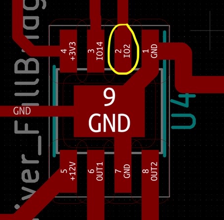
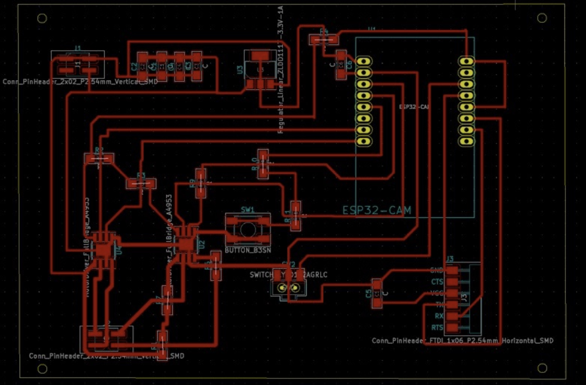
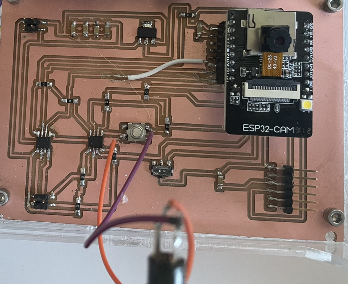
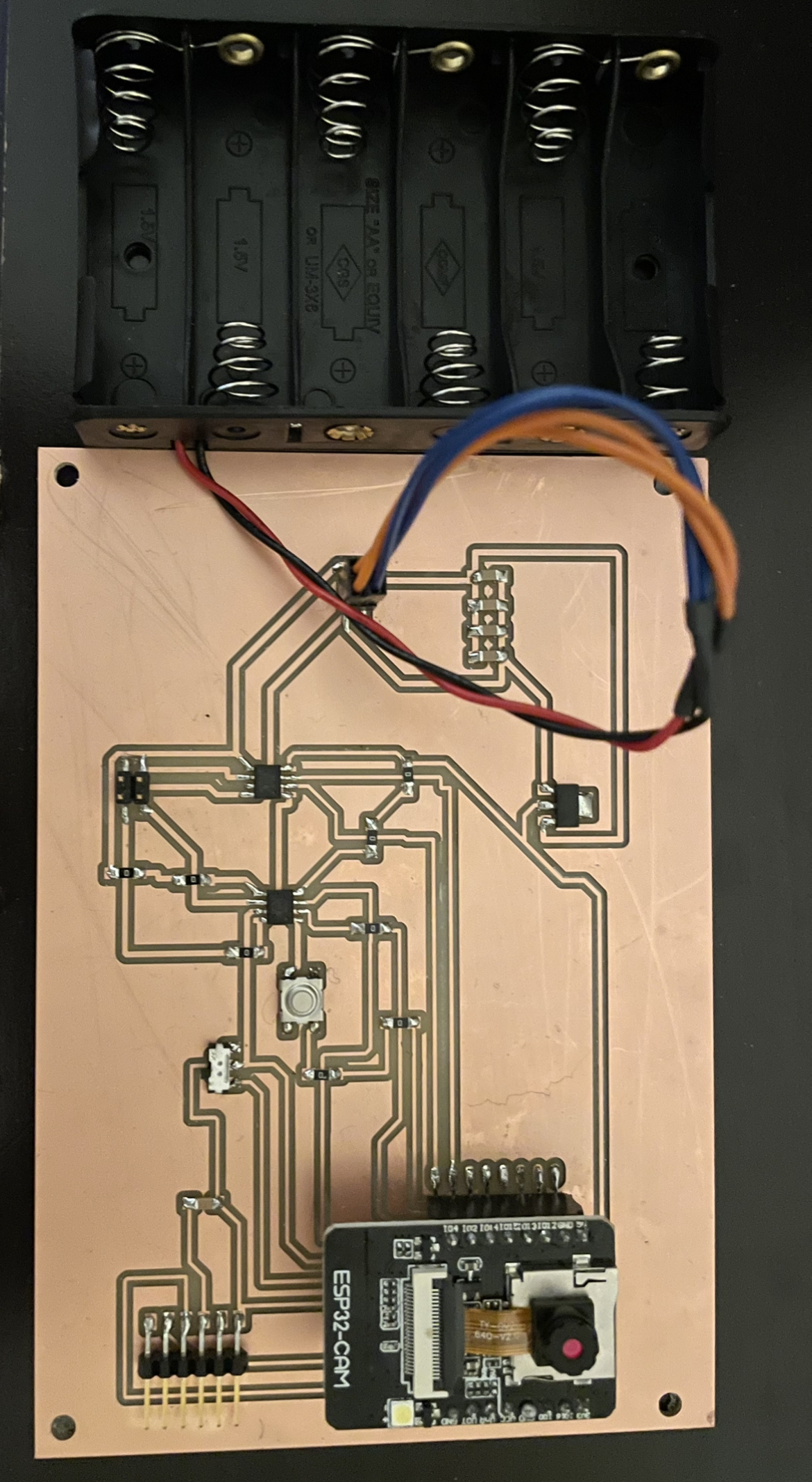
Even though I was working on this board continuously for two months, the ESP32-CAM would not upload my code successfully every time. I would either get a Brownout error or an error saying that it couldn’t find my ESP32. Here is a screenshot of the error statements I would receive. Just before I thought I exhausted all of my resources and asked all the questions I could think of, Quentin told me that I should be using a 5V regulator, not a 3.3V regulator. Quentin helped me use an oscillator to probe all of the components to see how much power was coming out of each one. Once I switched the 5V regulator for a 3.3 V regulator, it still wasn’t working. Next, we looked at the ESP32 Pinout Reference website to ensure that I was using the correct ESP32 pins. Next, we probed the ESP32CAM pins and found that the IO4 pin was no longer working because it wasn’t getting a voltage. Quentin suggested that I cut the trace that was connecting the motor driver to pin 4. Next, I used a wire to connect pin 2 to the following leg on the motor driver:
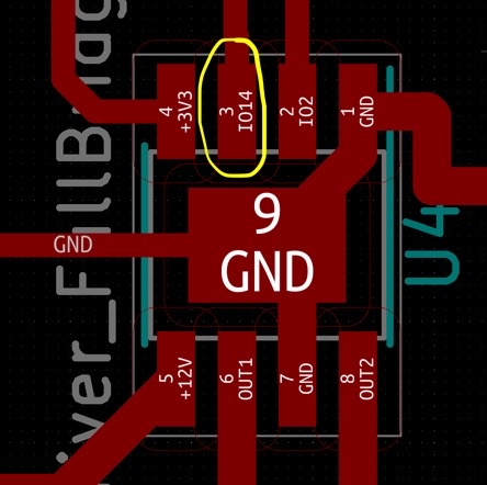
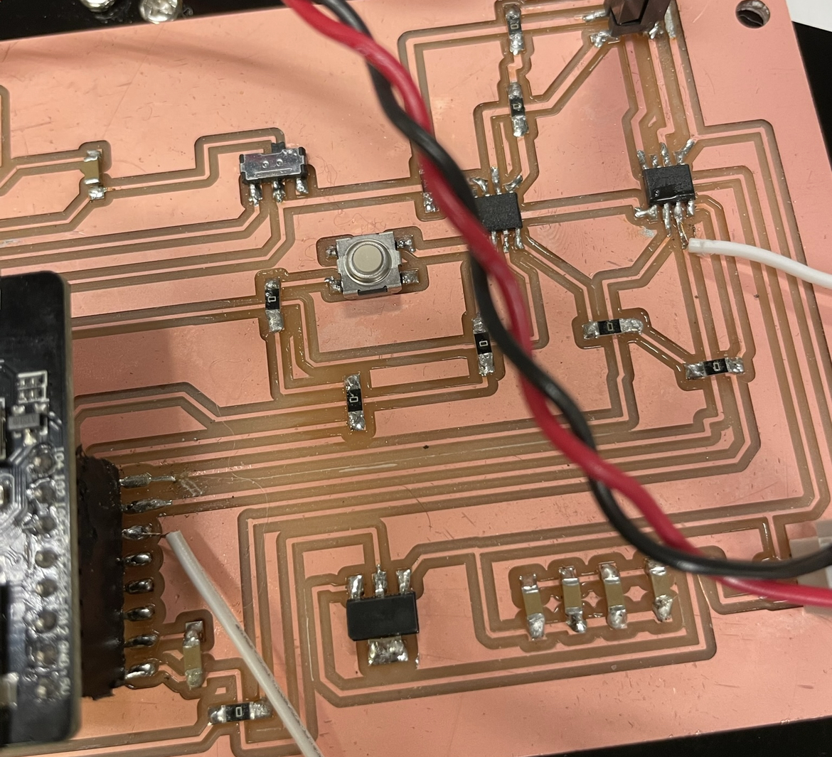
Unfortunately, both tires still weren't working at the same time. After hours of debugging this problem, I realized that I soldered the wire to the wrong trace. I connected I014 to a diffferent leg on the motor driver. Unfortunately, still only one motor worked. I spent hours trying to debug this problem. Finally, when I compared the milled trace to my KiCad schematic, I realized the board had conneccted two legs (one leg was connected to IO2)of one of the motor drivers together. As a result, I lifted up the motor driver and I used a box cuttter to cut the two traces and it worked!! Yay. This entire process of working on the same board for two months helped me understand how to debug problems with PCBs because anything that could go wrong with my PCB went wrong.
Capture Image file
KiCad files
Link to interface files
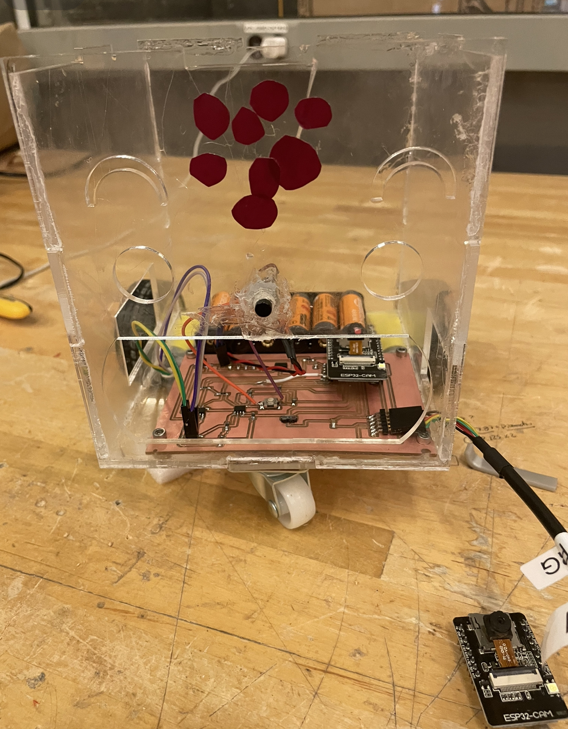
Making the Robot Body:
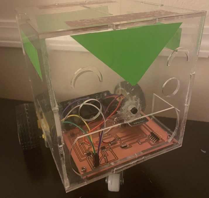
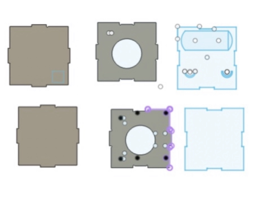
In order to make the robot body, I decided to use the same Fusion 360 dxf file that I used from Week 4: Make Something BIG - CNC Machining. Please look at that page for more explicit details on how I created the cube. It definitely was not as easy as it seems. I didn't use any plug ins to make the dog bones. Essentially, the robot body is a perfect cube. I spent a whole day trying to insure that the PCB board, battery pack, and screws were perfectly alilgned. Also, it took me a very long time to paramaterize everything. Unfortunately, I am still learning how to do this skill. My process for many hours looked like this: 1) create a parameter for the distance two screws should be from each other 2) lazer cut cardboard 3) screws are to far apart 3) change parameters 4) Fusion 360 didn't update using the parameter. 5) delete the objects I created on Fusion 360 6) create the same object again. Nevertheless, here are a few tips:
1. You can edit a dimension that you already created. You don't have to delete a sketch if you want to change the dimensions. I wish I knew this because it would have saved me several hours. Click on Sketch Dimension, then the number that corresponds to the dimension that you created for the object.
I did lazer cutting to cut the acrylic. The acrcylic was about 3 mm wide. It took me several hours to assemble the robot too because I was looking for screws and ensuring all of the screws could fit perfectly on the bottom of the robot.
Although making the box looks easy, it’s much more difficult than it looks. Even putting the box together took a while. Initially, I tried to use super glue. I tried to put the acrylic robot together by myself for about 30 minutes without any luck. Then I tried to use acrylic glue. Acrylic glue didn’t work either. It was time to ask for help. This was definitely a job for two people. Thank you so much to one of workers at the EDS lab who helped me. I held two of the sides together, while the other person put the other two sides of the box together. He then helped me put clamps on the side of the box. Once the EDS lab closed, I removed the clamps to move to the CBA, so I can clamp them for a longer time. Since I’m inexperienced with clamping objects, I clamped the body of the robot to tight and the face of the robot cracked.
Robot body dxf file
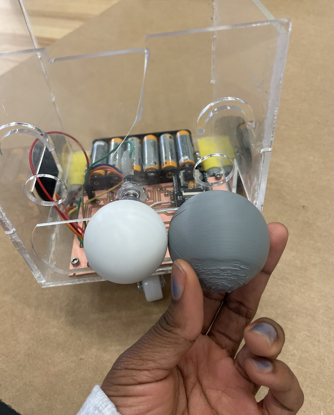
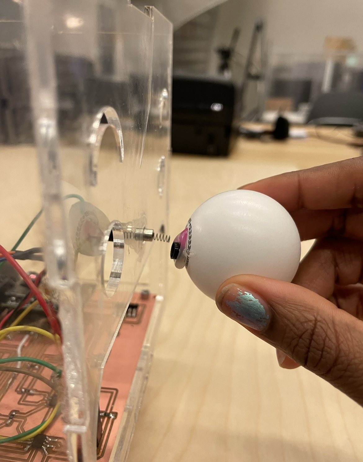
Additionally, I tried several times to 3D print a sphere. This sphere would be attached to the button, so that the robot wouldn't need direct impact in order to move like a bumper car. Initially, I tried hot gluing the sphere onto the button. However after a few hours of testing, the sphere would be broken off and would remove the cap off the button. After trying this several times, I thought it would be best to not use the 3D printed sphere. I settled for just using hot glue to solidify the button. sphere stl file
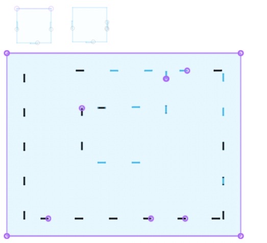
Making the Maze:
I used Fusion 360 to create the maze. I parameterized everything. This took me a day or two because I'm still learning all of the complexities of Fusion 360. I used the lazer cutter first to ensure that the distance between each slot was correct. I did this about 10 times to ensure that my calculations were perfect. Nevertheless, I created slots for everything. Also, I had to ensure that the walls were press fit. Meanwhile, I decided to use the ShopBot milling machine to create the slots and I lazer cut the walls of the maze. I found all of the materials in the CBA shop. After I milled the slots for the walls, Zack stated that I should mill another board to make the board with the slots flat. Next, I used the a drill to put the two boards together. This was one of the first times that I used a drill. As a result, I burned my finger when I touched the nail that I was trying to drill. Ouch! Now I understand the importance of wearing gloves. I used hot glue and wood glue to put the walls together.
Please see my Week 1 page if you would like more information on my how I went about making the maze:
Link
Maze dxf file
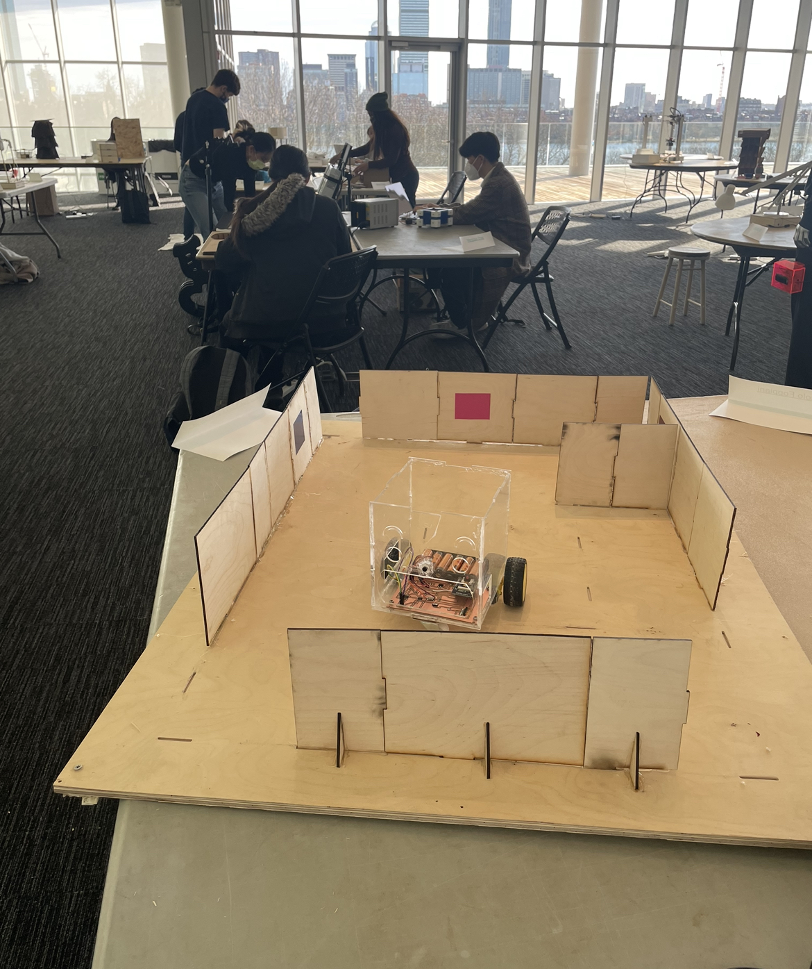
Making the Robot Act Like a Bumper Car:
I thought that making the robot navigate through the maze would be the easiest part. The main issue that I was having is that my robot couldn't move in a straight line, which is problematic because I need the robot to navigate through the maze. I realized that one of my dc motors was more powerful than the other dc motor. As a result, I replaced the dc motor that wasn't as powerful. Once I replaced the dc motor, the robot still veered to the side when I tried to make the robot go straight. Next, I started learning how I can change the speed of both of the tires,so they could both go at the same speed.I used the delay function to make each wheel turn for a certain amount of time. The delay function pauses the program for the amount of time (in milliseconds).Unfortunately, this still didn't ensure that the robot always veered in the desired direction because the swivel wheel always turned in a random direction. I continue to try different dc motors, but to no avail.
Robot Bumper Car Code
KiCad files
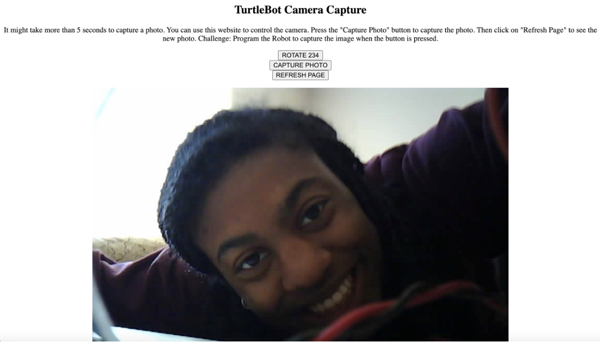
Making the ESP32-CAM take photos:
I made a website that captures an image on the ESP32-CAM. This assignment was much more challening than I thouhgt because my ESP32 CAM was getting burnout errors. Luckily, Quentin was able to help me. I followed this tutorial: Random Nerd Tutorial. Seek Week 10 for more details:
Camera Capture video
Here is a video of how the camera capture works:
Robot Bumper Car Code
Camera Capture video
Capture Image file
KiCad files
Assembling the robot:
Assembling the robot took me longer than I expected because it took me a day to find all of the materials I needed, and a lot of trial and error to ensure that the system was properly integrated. One component of the robot that I made was the battery pack for the car. I needed to make a battery pack that could be conencted to a 4 pin header. Unfortunately, my lab only had battery packs that were connected to two pin headers. Here are the steps that I took:
1. cut two wires in half
2. twist the two sides of the wire together
3. solder the wires together
4. add super glue to the sides of the header