Embedded Programming
The assignment for this week was to read a microcontroller data sheet and to program our boards to do something. First, I read the datasheet for the ATtiny412 .This week I continued to build off of what I did in Electronic Design week because the board I created satisfied the requirements for this week. Here is a quick recap of what I completed in the Electronic Design week:
I spent a vast amount of Friday and Sunday trying to create the circuit board and trying to understand how to use KiCad and Eagle. I started using Eagle, but I decided to use KiCad. I decided to follow this board, hello.t412.blink.
This board has a serial port on it and it mirrors back text to it. There is a serial port that connects to the serial pin on the ATtiny412 and a serial port that connects to the programming port.
KiCad was much easier for me to use because the names of the components were easier to locate. Unfortunately, I was really confused with how Eagle required me to use vias. Also, after working on Eagle for several hours my schematic didn’t sync with my board design. For some reason, my WiFi stopped working, so I was making a lot of changes in my schematic design, but they were not reflected in my board design. Unfortunately, I didn’t realize that these two files were out of sync until a long time. Nevertheless, I’m glad that I switched to KiCad in the long run.
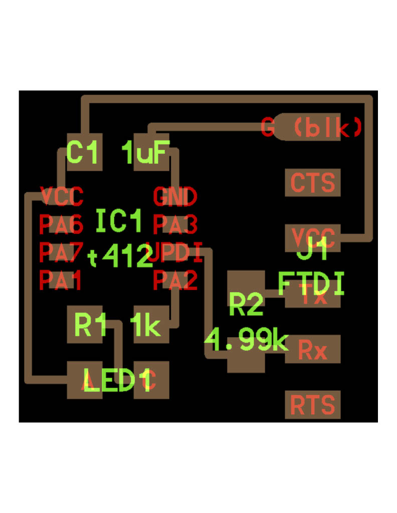
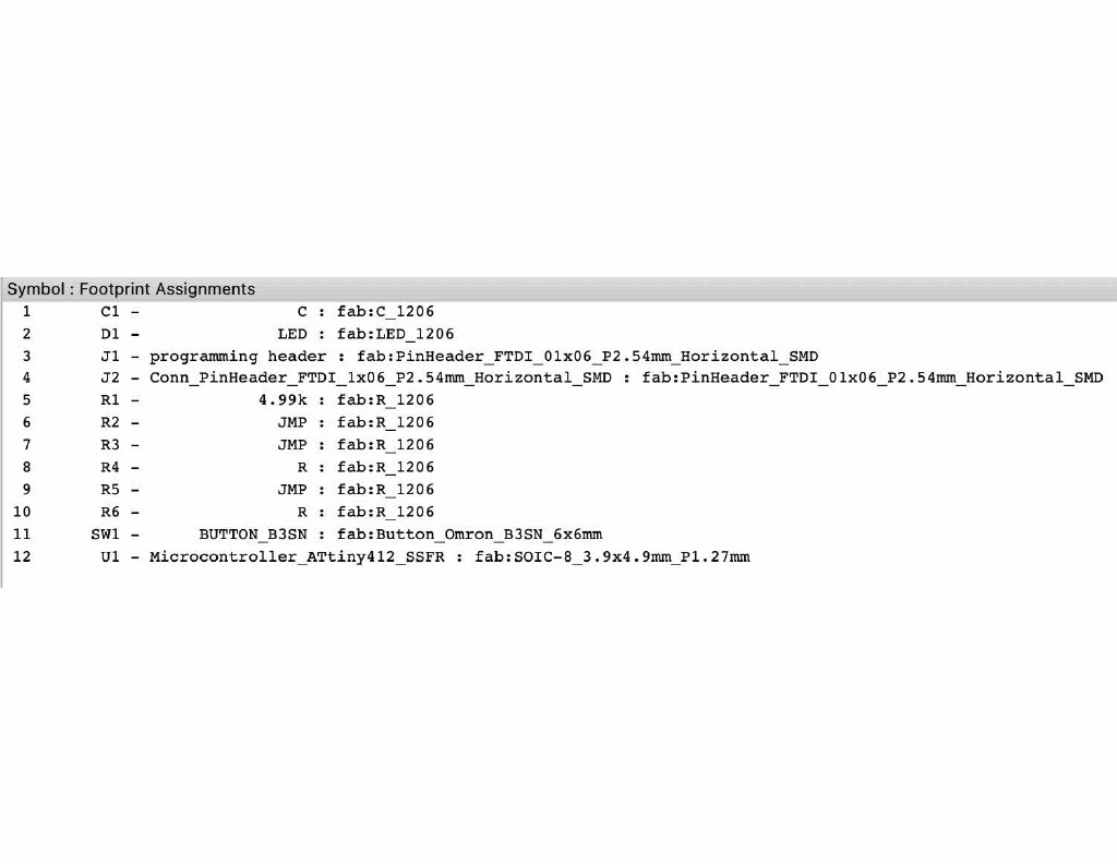
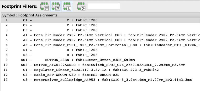
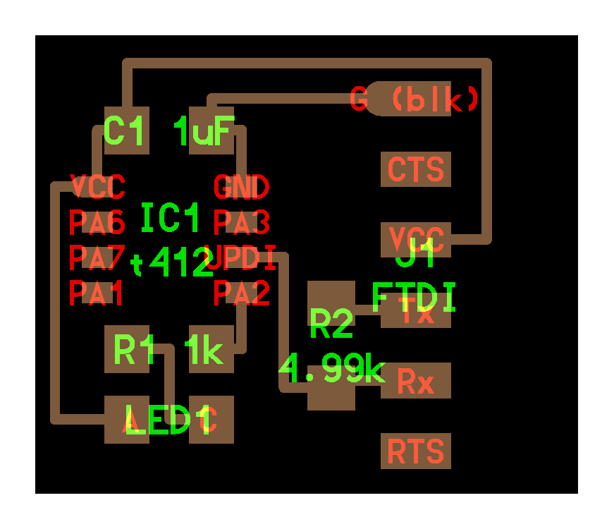
Here are all of the components that I used in KiCad:
Here is the board and schematic:
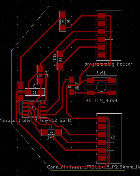
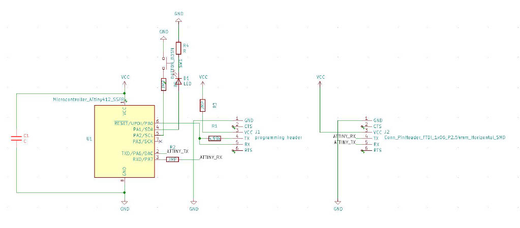
Zach’s recitation was extremely helpful. I connected some of the components with labels if there were a lot of wires in one place, such as “ATTINY_TX” and “ATTINY_RX”. One way that I made the board design easier to read was by rotating some of the components. In order to add the LED, I decided that it was best to put a wire through the middle of it. Also, it took me a couple of hours to organize the schematic because the idea of adding jumper resistors was new to me. I couldn’t find multiple ways to route the connections easily so it was mainly just trial and error. After all of the components were in place, I decided to make my board look similar to a ship.
However, I forgot that the programming header needed to be close to the edge. As a result, I changed the shape of the board. After, I used Inkscape to export my image. This was probably my third time using Inkscape, so I was little rusty. I managed to fill in the outline area with black and combine the two layers.
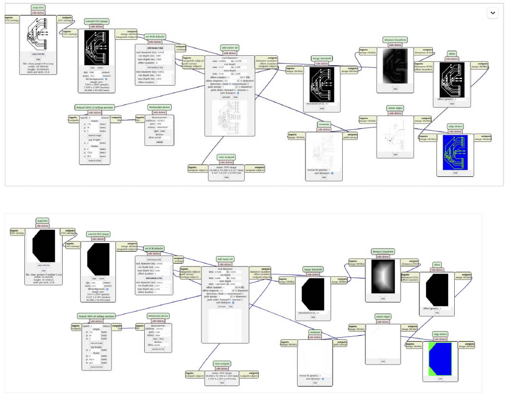
After I exported the two svg files, I went to http://mods.cba.mit.edu.blink
and I used the Roland SRM-20 PCB svg. I failed at milling multiple times. The first time that I tried to mill, the traces were not going deep enough. Then the 1/64 end mill broke. After, the end mill stopped designing my board in the middle of the design. After I changed the 1/64 end mil, the pcb was milled correctly.
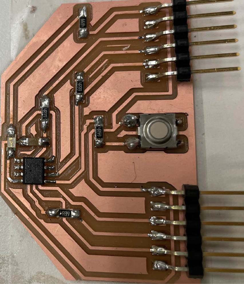
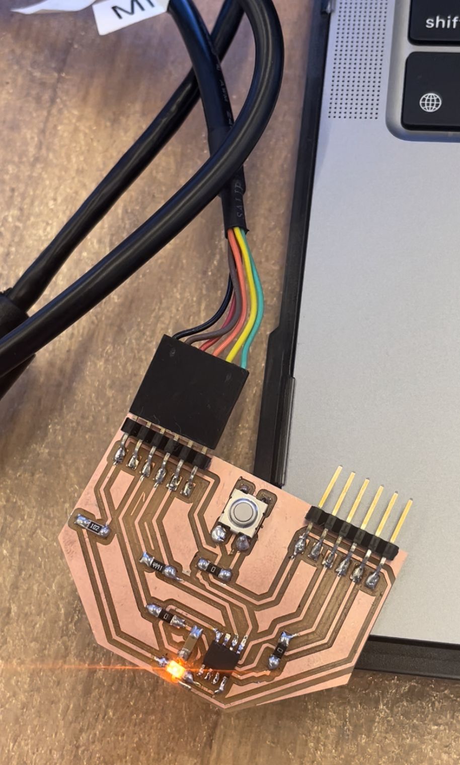
The soldering portion of the project went smoothly. The first time that I was soldering, the flux was almost gone. Nevertheless, trouble was just around the corner.
Next, I wanted to program the board. However, Arduino wasn’t recognizing my board. As a result, Harrison showed me that I had to change some of the jumper resistors from 5 ohms to 0. However, that was not my only error. I accidentally connected my Atiny to my LED. First, I tried to get rid of the connection by using the braid. Zack helped me remove the connection by using one of the cutting tools in the CBA shop. I tried to connect my board to Arduino again, and it connected to Arduino. However, I was getting the following error: UPDI initialization failed.
So I replaced the LED, still no success. Huge thanks to Jake and Harrison for helping me to use the multimeter to see if did my soldering job correctly. After using the multimeter twice, Harrison suggested that I replace the Attiny. After I replaced the ATTiny, the echo program and the light worked!
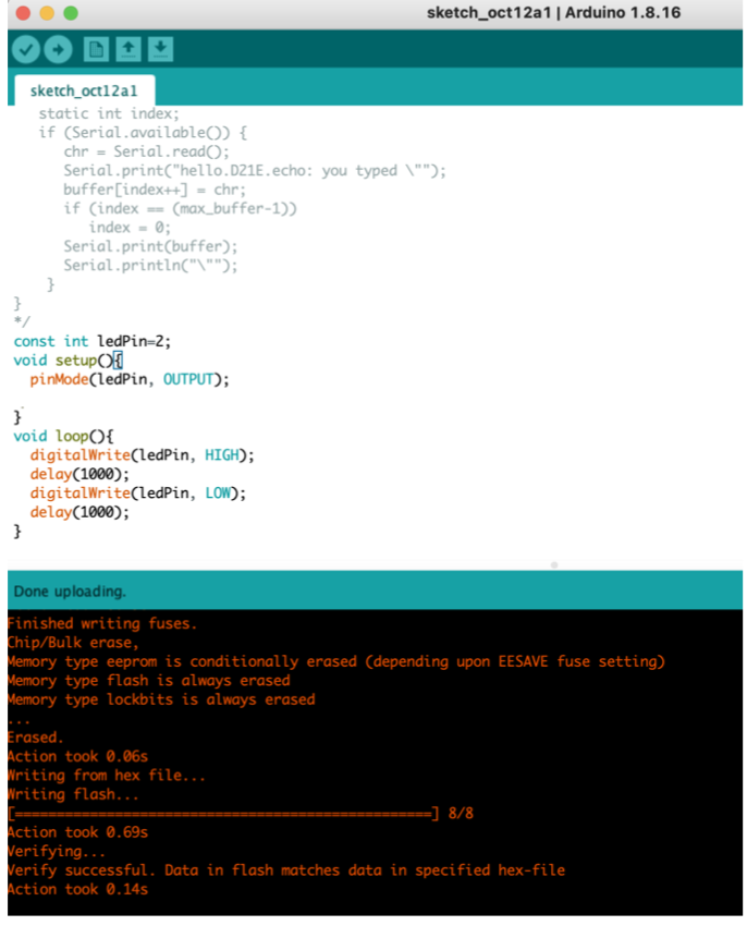
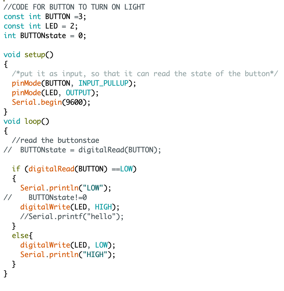
Here is the code for the button to turn on the light: I used Neil's starter code and changed it so that it worked with my board. My main problem for getting the button to work was that I was using "INPUT" instead of "INPUT_PULLUP".
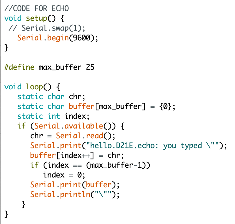
Here is the code for the echo:
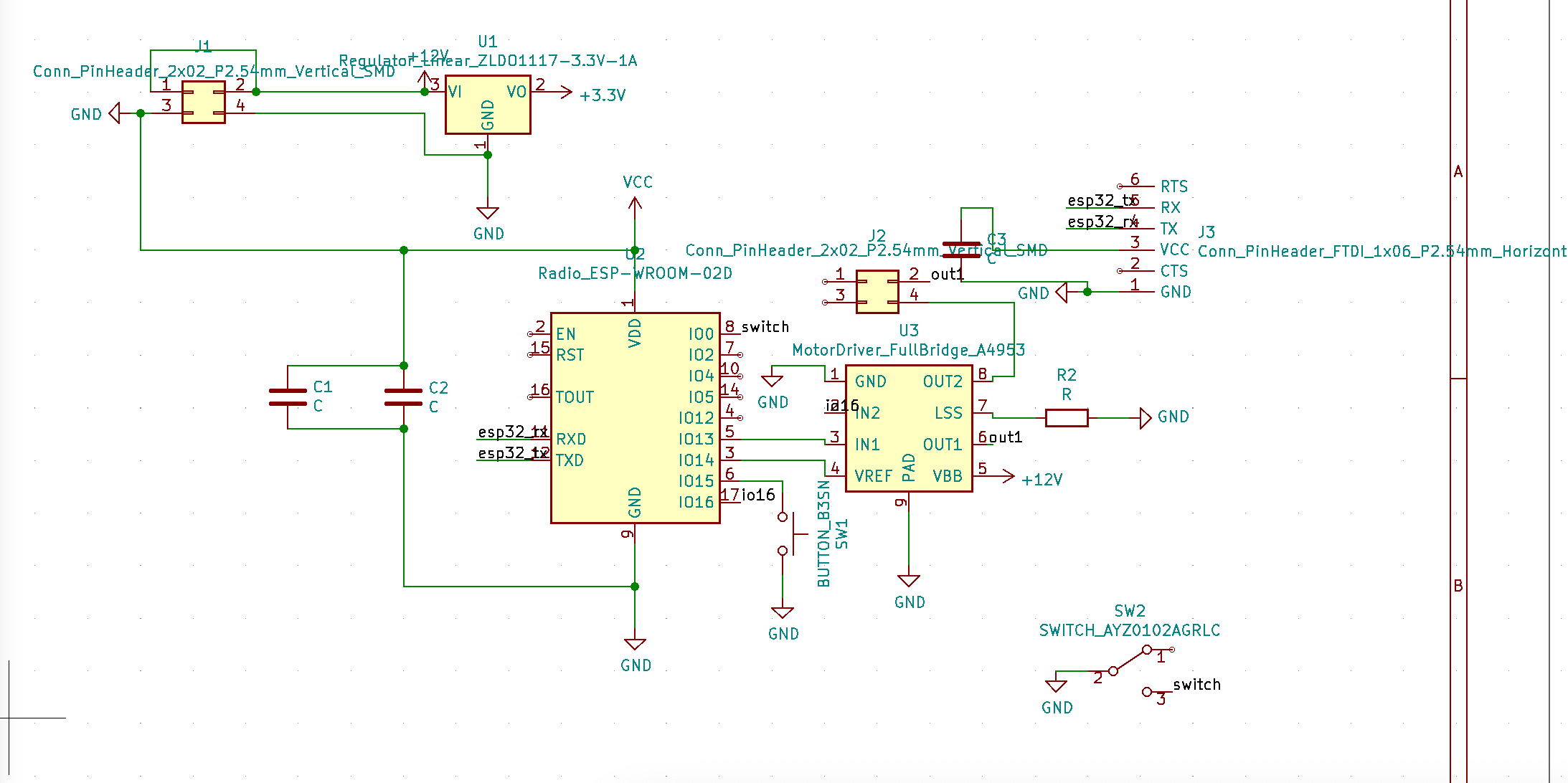
Also, I created the schematic for the H-bridge motor:
Link to electric board files and videos
Board code file
Board flickering video
Board echo video