This week, we had to redraw a board, and include a button and LED. Using Eagle was equal parts frustrating and rewarding (which I suppose is why its part of Autodesk). I still have trouble determining best practices for routing traces, but I don't know that there is a better way than guess and check.
Many people in my section were working with ESP32s, so I decided that would be the best reference. I downloaded the FABLAB library, but also had to incorporate "supply1" for certain components (resistors, capacitors, ground) and download a separate ESP32 component online. Before adding the LED, I decided to trace out everything, including a resistor (which would essentially be the LED). The button connections were a bit strange to figure out, but I reviewed the Eagle tutorial video.
First Eagle Schematic
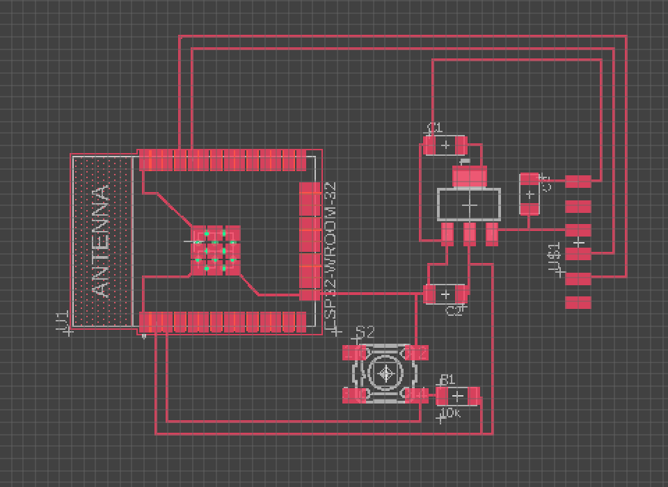
When routing the connections, I realized that Eagle has some logic to determine what eligible routes exist (it's not just where I connected it in the schematic). Because of this, I had to do a bit of spatial rationalization in order to determine where to place the components. After that, I did my best to route connections, trying to avoid any intersections. I also left spaces around the ports (for future projects) and an empty space near the FTDI connection (for the UPDI).
Routing the Traces
I added LEDs to the Tx and Rx pins of the FTDI cable in order to see when data was being transferred.
Adding the LEDs and Switch
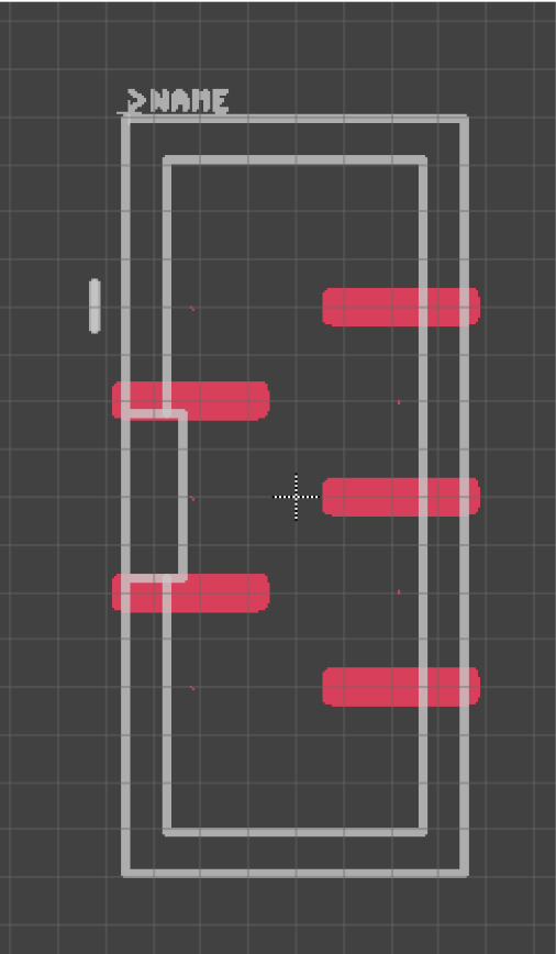
Next, I decided to add 5x1 connectors to the board in order to make it easier to add additional components. However, I couldn't find a 5x1 connector in the library. I edited the 5x2 connector so that its teeth orientation matched the 5x1 connectors in the lab.
Edited connector
Once I created the connector, I tried to connect as many pins as possible from the microcontroller.
Added pins to schematic
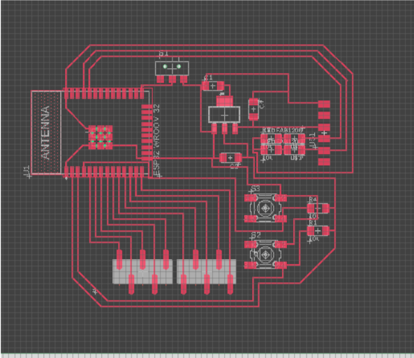
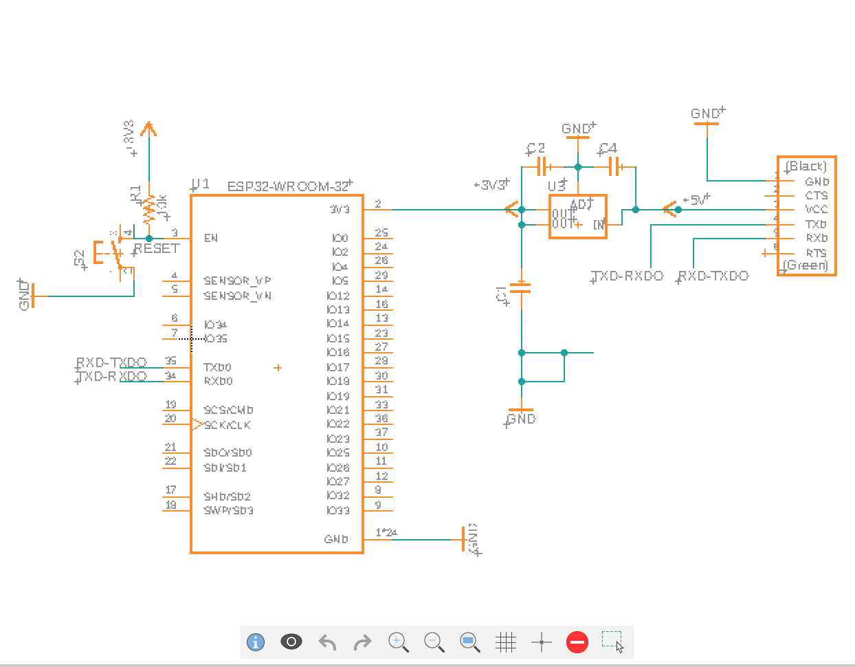
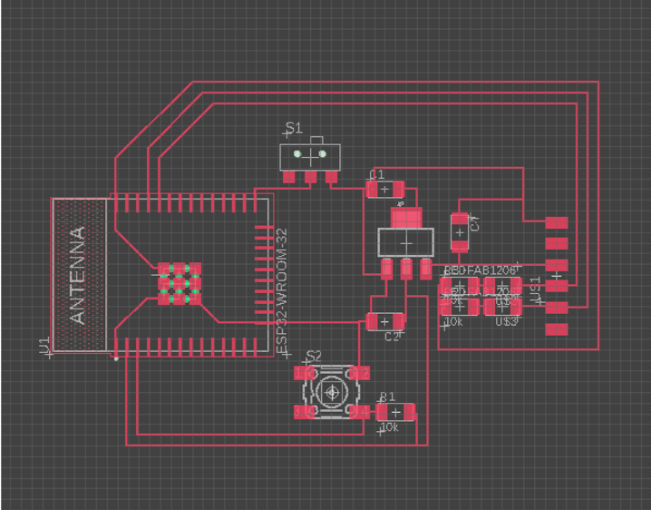
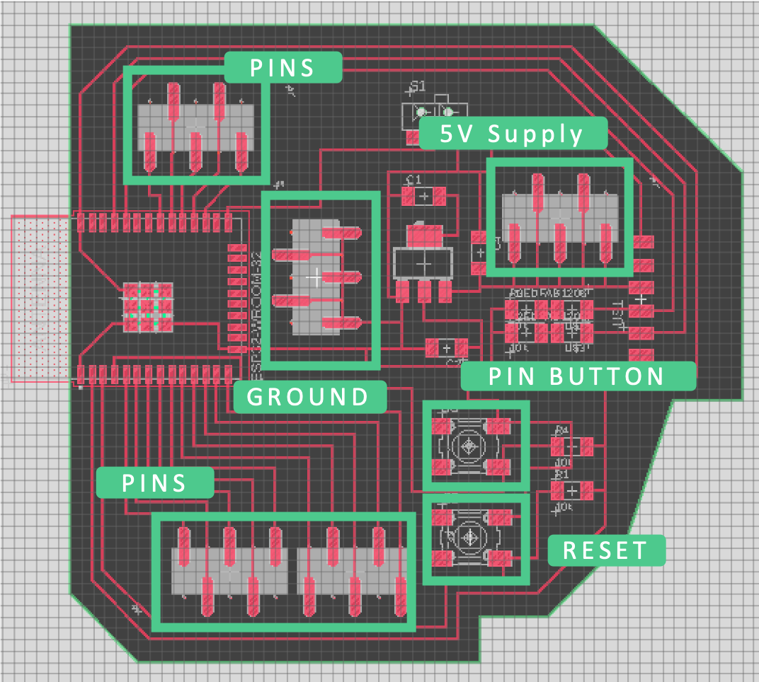
Part of the assignment was adding a button, so I decided to add that in the final iteration. I also decided to add three more 5x1 connectors. One would serve as a 5V supply, one would serve as a ground connection, and another was just another row of pins.
Complete Schematic
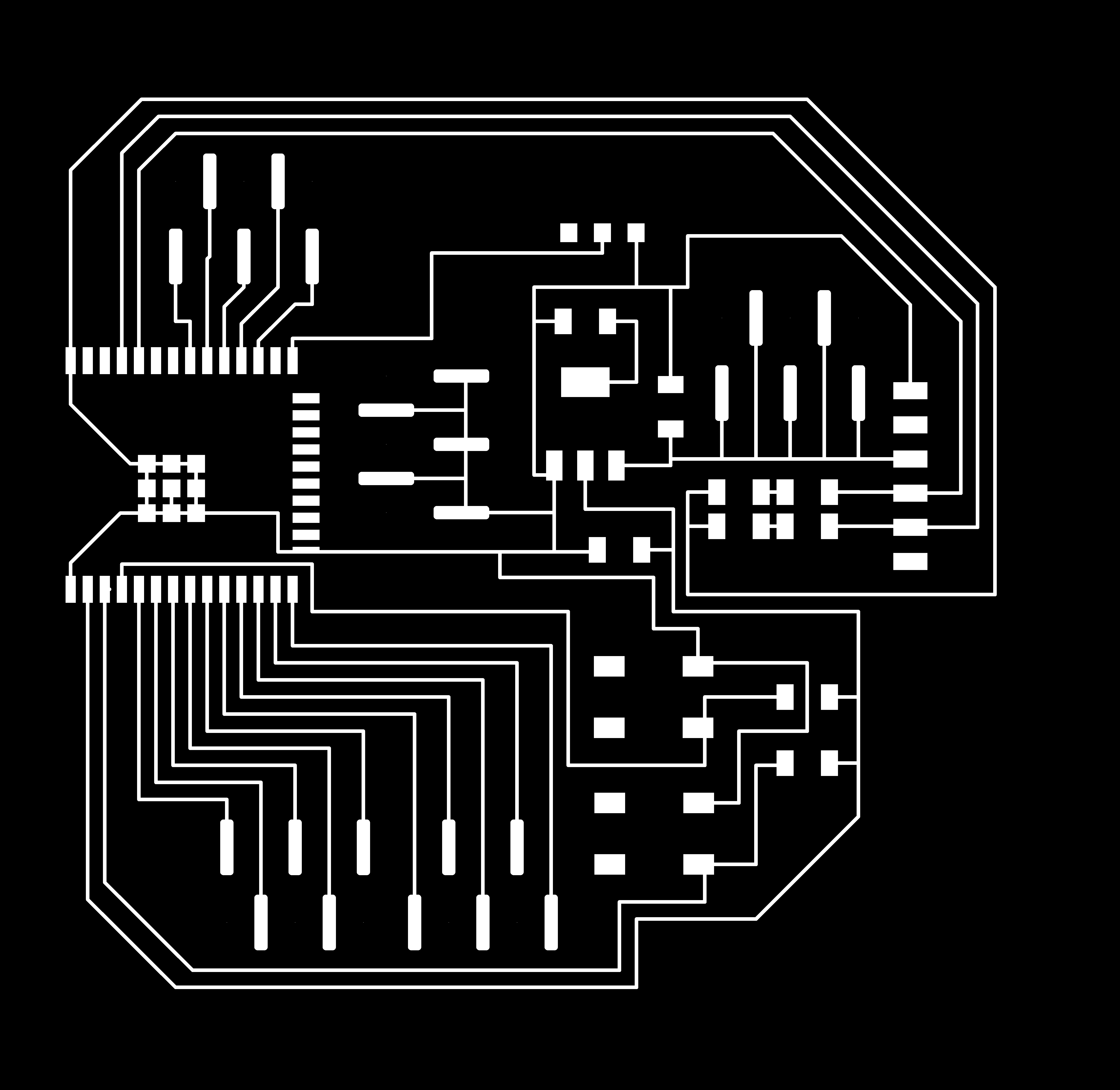
In order to create traces in Eagle, I used the "display" command to isolate the layers that I needed. I had to manually trim one of the pads on the lower right corner of the ESP32 in Photoshop to ensure that the traces wouldn't be too close to each other.
Inner Trace
 Outline Trace
After I designed the board and made the traces, it was time to mill it. This board was fairly big, so it took over an hour to fully mill.
Milling the PCB
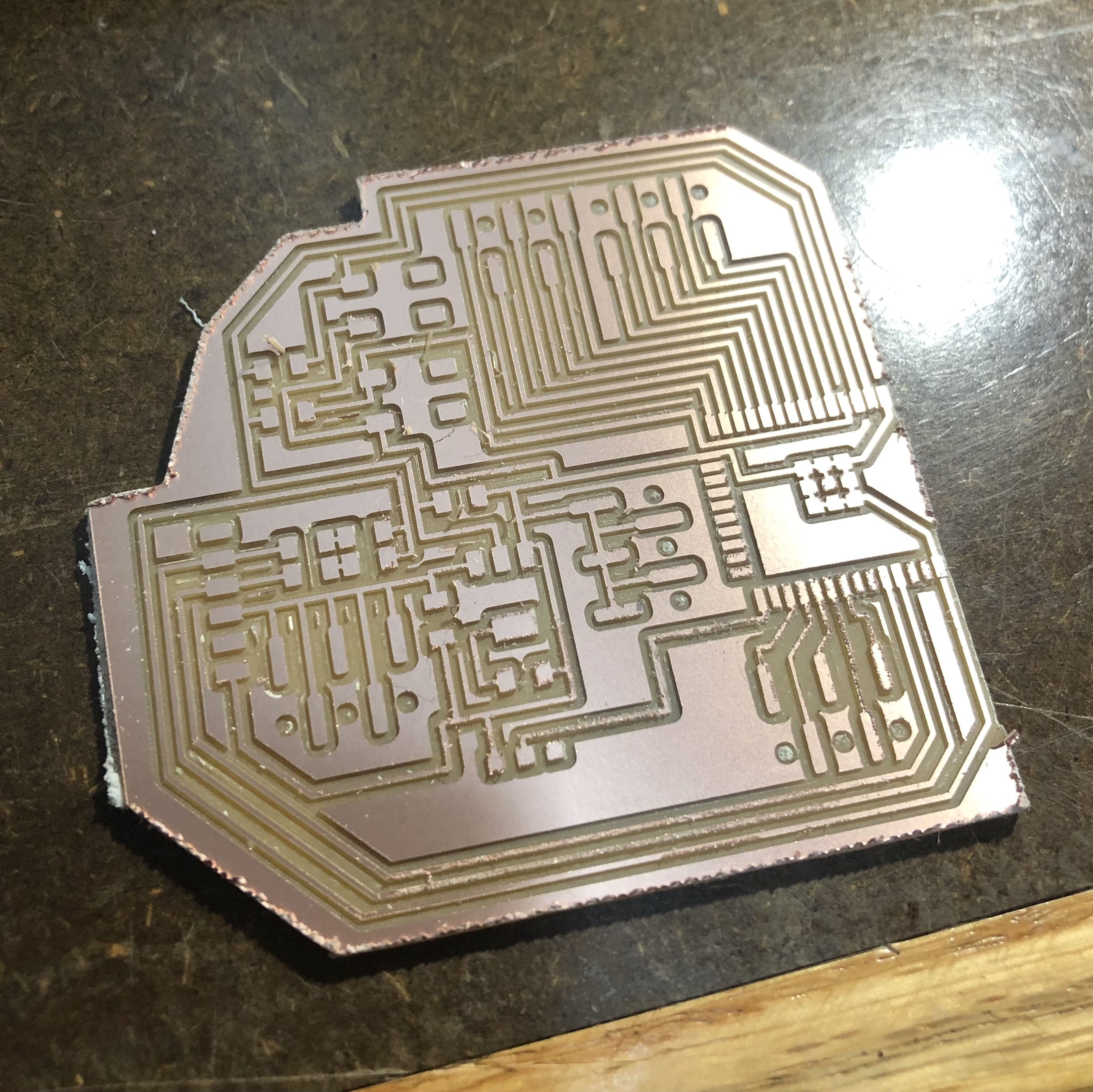
The board cut out fairly cleanly.
My PCB Board
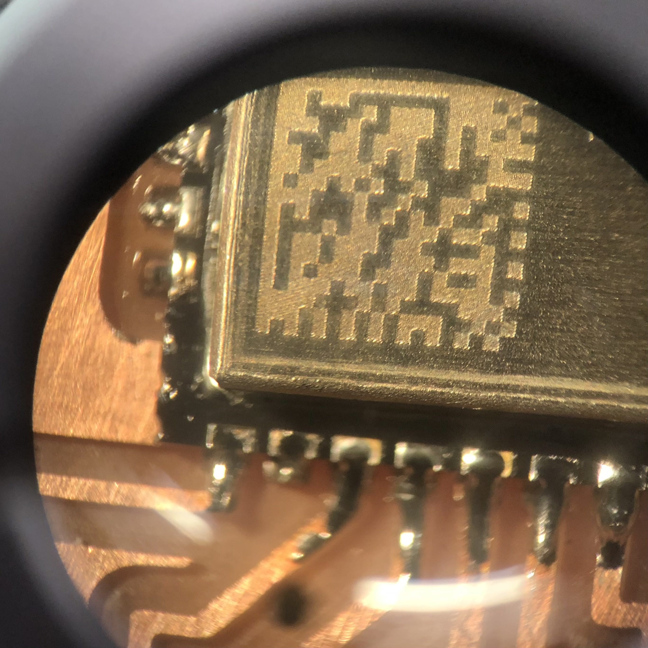
I had to stuff the board. The most difficult part was soldering the ESP32. I messed up the first time, and I had to redo the board. The second time, I felt more comfortable with the timing, and I think all the connections were appropriately made. The rest of the board was a piece of cake, comparatively.
Trying to solder the ESP32
Finally, I was left with my first board!
Finished Board

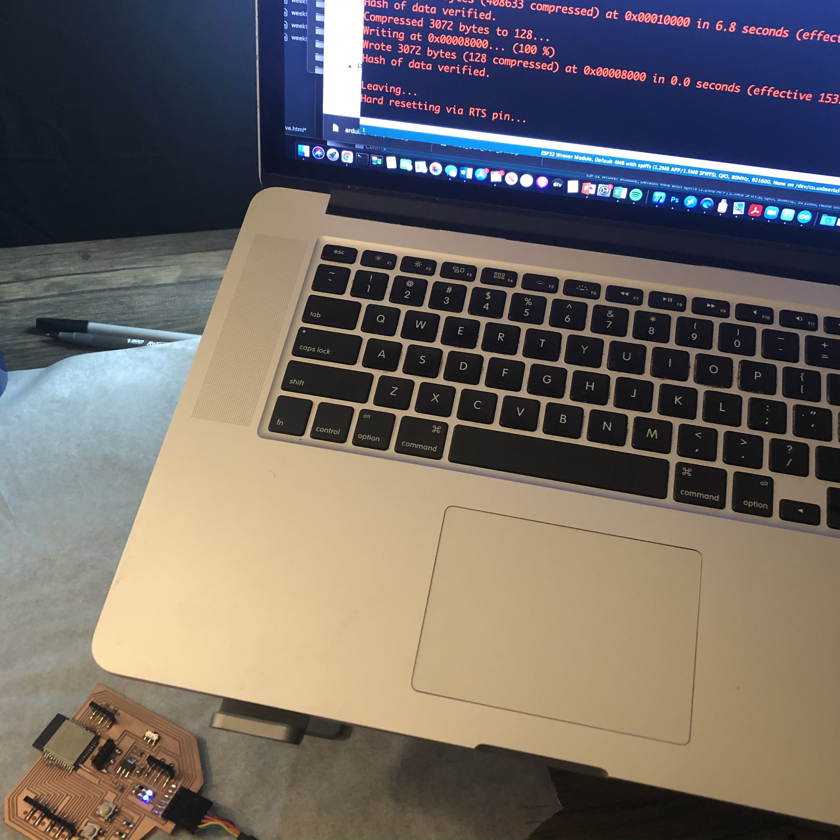
I connected the board to the FTDI cable, and the LEDs turned on. The blue light turns off when the board is reset and the white light is supposed to blink when data is being programmed onto the board.
Blue reset light
The board successfully connected to Arduino IDE!
Finished loading