This week we had to measure something using a sensor. Temperature sensing was one component of my final project that I wanted to learn this week.
Nathan showed me how to use a thermistor (thermal resistor) in order to read temperature. By passing current through one end of the thermistor and attaching a resistor to the other end, you can measure the difference across the thermistor, which can be read by the microcontroller.
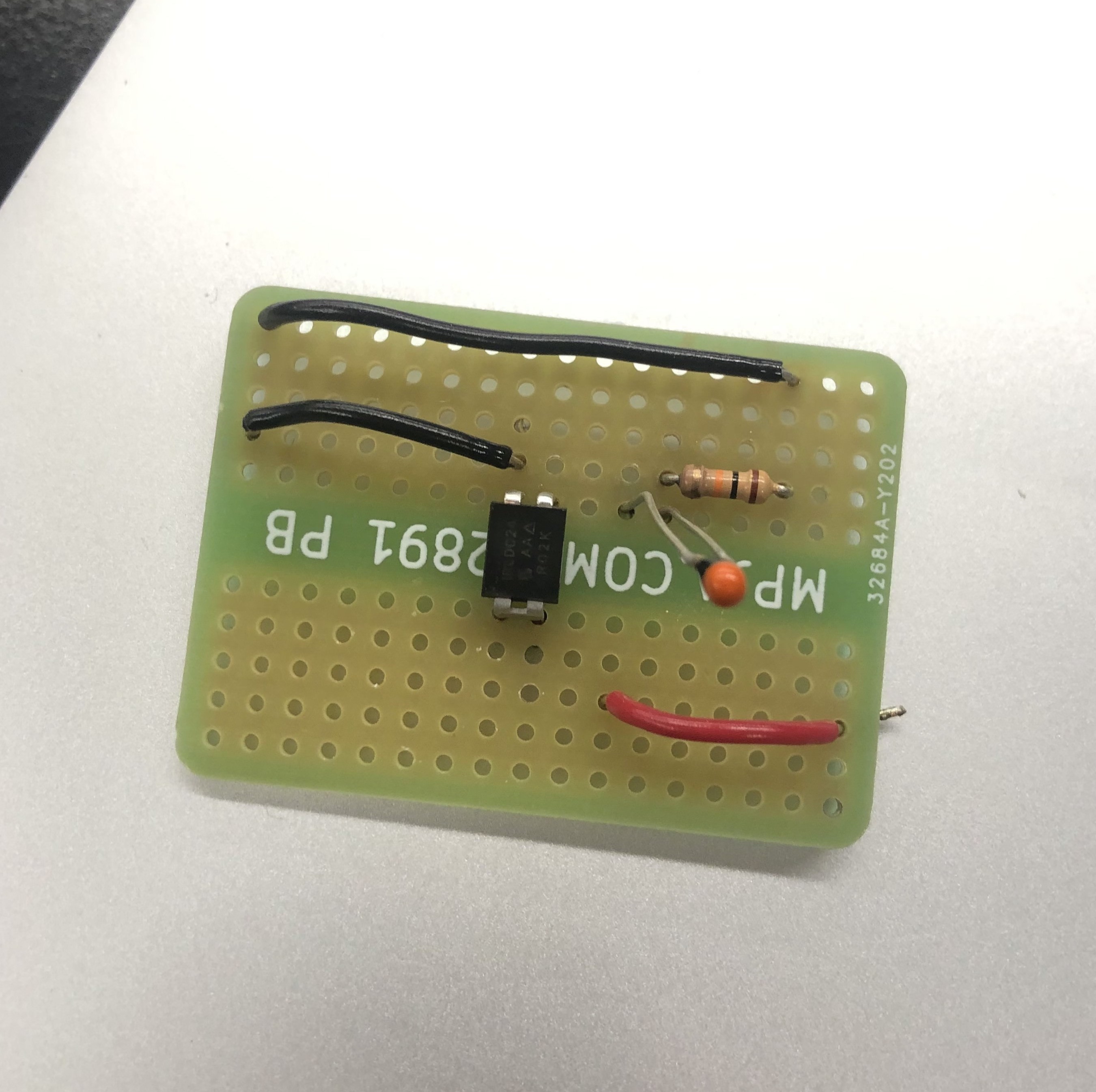
I knew that I eventually wanted to connect a fan, so I made a tiny breadboard that included a transistor, thermistor and resistor. I had to add a ground wire to the end of the resistor.
Breadboard with thermistor
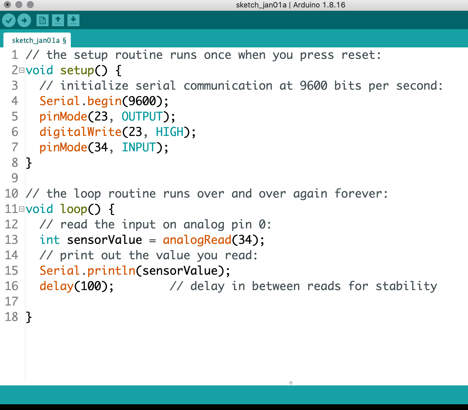
In terms of connections, I had to connect the first leg of the resistor to a port on the microcontoller, and then the other leg to another port. Then I had to program it in Arduino. This was the first Adruino program that I drafted independently! (which meant there were glaring mistakes). The thermistor worked by changing its resistance in response to different temperatures. That difference could be read by any analog port into values (which could then be interpreted as specific temperatures). What I had to do was get an analog read from the thermistor, so I did an analogRead function and then have the values print out every 1/10 seconds.
First sketch
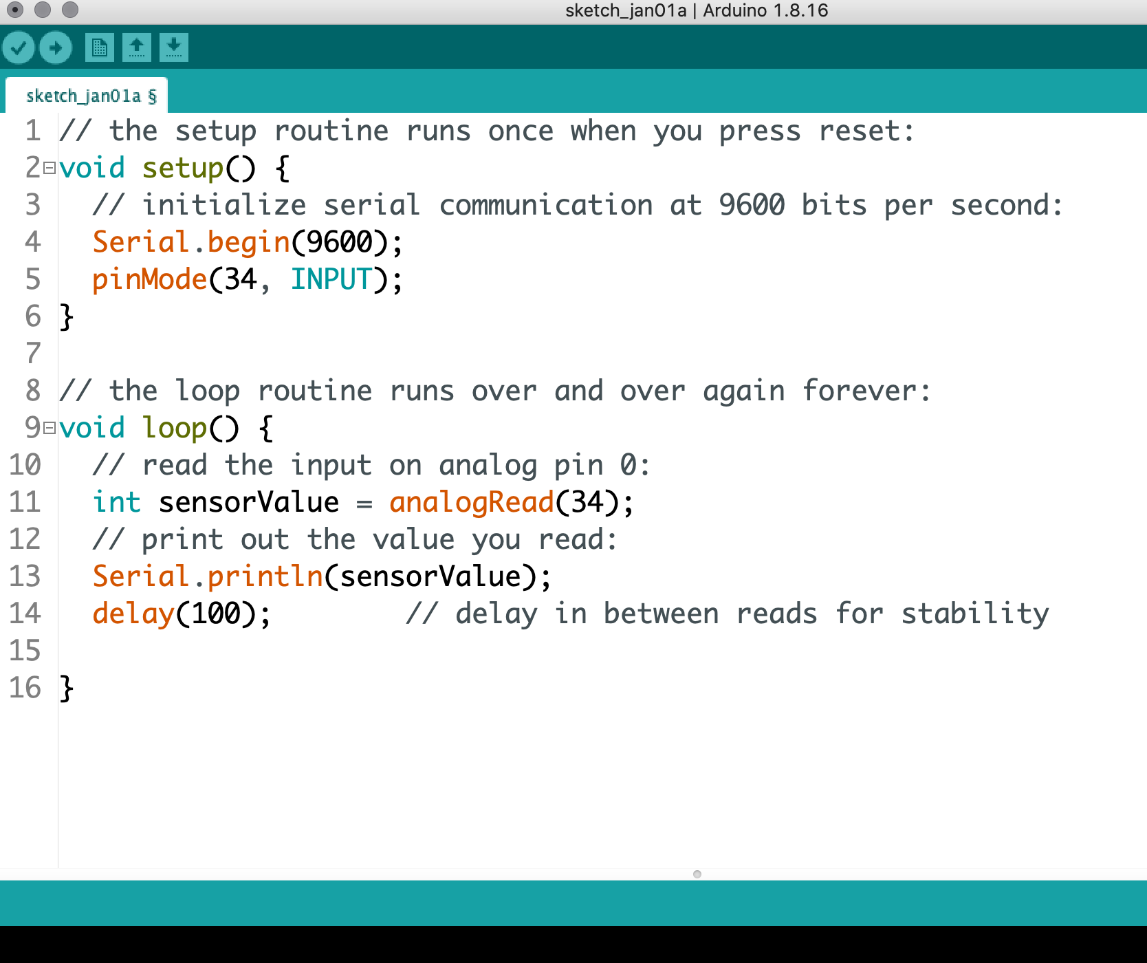
Do you see the mistake I made? I forgot to include the output pin! So no current was flowing through and I wasn't getting a reading. Once I added the output pins, the sketch worked properly. I had to do some tweaking of the serial communication speed (9600 worked out).
Corrected sketch
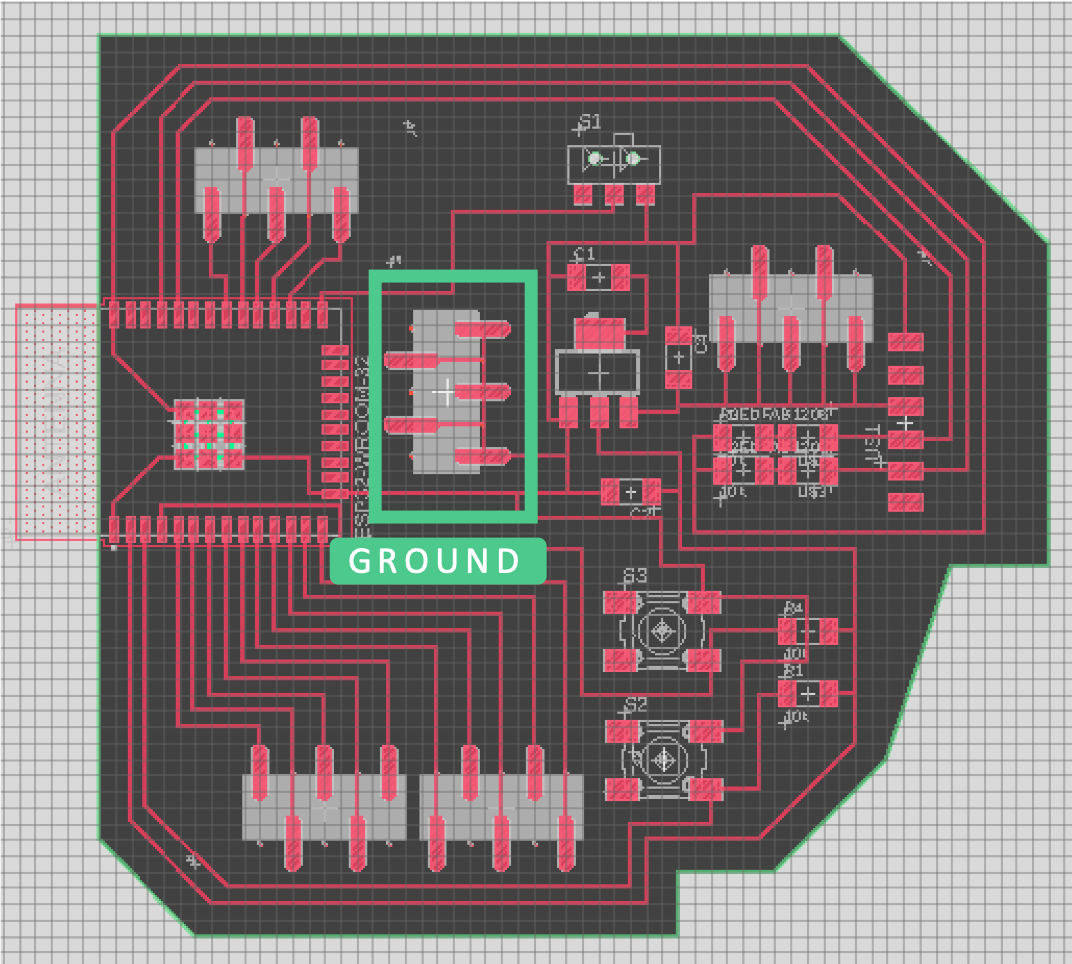
My board from Week 5 was useful since it had multiple ports and ground connection for the sensor.
My Board
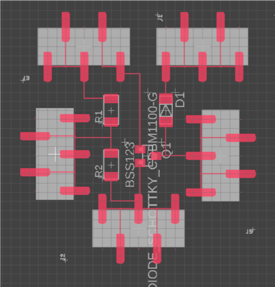
I milled out a small sensor board to replace the breadboard. First, I designed the board to hold the thermistor in Eagle.
Thermistor Schematic
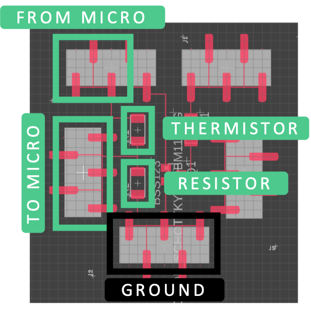
The top-left and middle-left connectors was connected to the microcontroller via port connections on my board. The thermistor and resistor were connected to the micro and ground. The ground connection on the small board was connected to the mainboard. This was a way to streamline the breadboard functionality.
Detailed Schematic
The traces look very elegant.
Interior Trace
 Outline Trace

This board was much smaller than the main board so it took under 30 minutes to mill.
Milling the sensor board
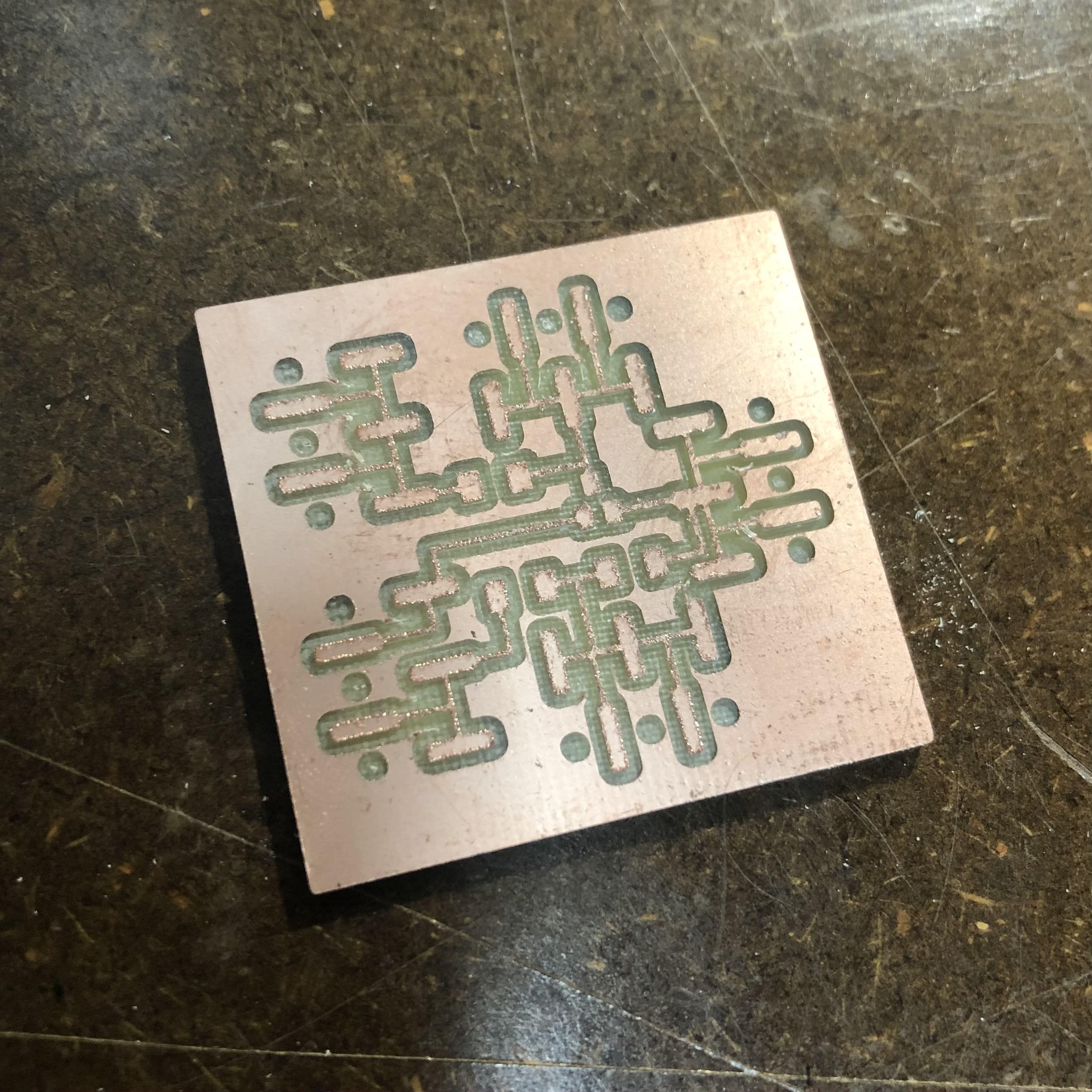
This was the board after being milled (it's around a square inch)
Mini board milled
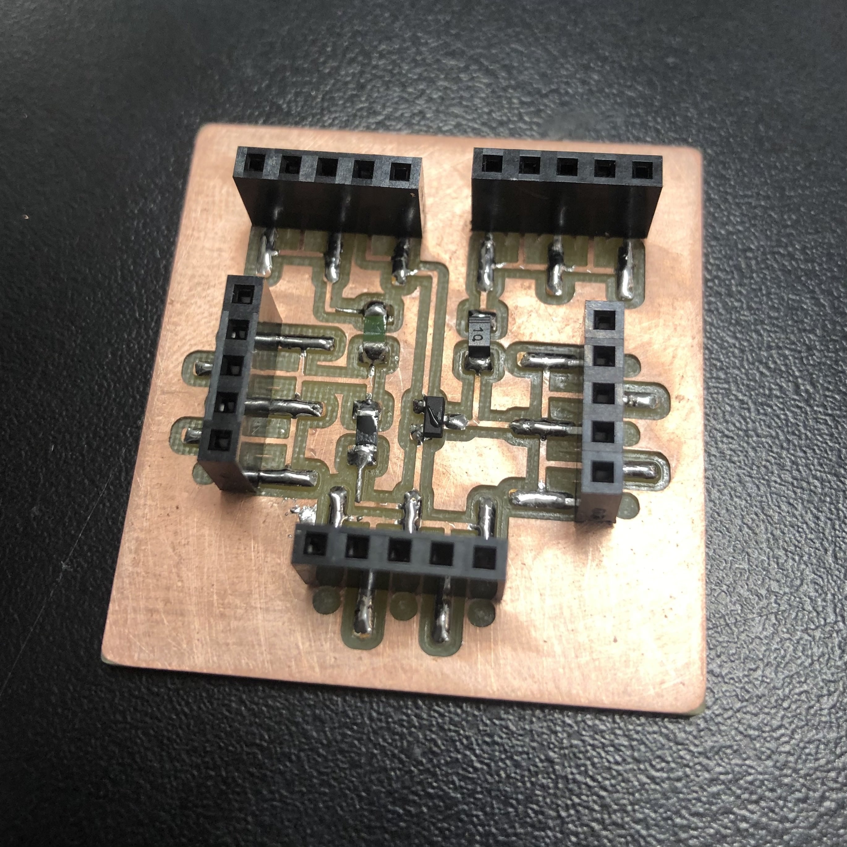
After stuffing, I was left with a very cute mini board that, when connected to my main board, could sense temperature.
Mini board stuffed