Final Project
The Idea
I really enjoy the puzzle game "Baba is You". "Baba is You" is a puzzle video game where a player forms rules inside the game by moving around tiles. The rule-making aspect of the game is really cool, so I wanted to do something related to that. I also think the character Baba is really cute. So, I decided to do a "Baba is You" inspired lamp, controlled by a sliding tile puzzle (like the 15 game). One can slide the tiles on the puzzle board to form rules like "BABA IS [COLOR]" to change the color of lamp to [COLOR].
The lamp will be in the shape of the main character Baba:

The sliding tile puzzle will look something like this:

Components
- Baba shaped lamp shade (3D printed - PLA)
- Neopixel strip (16 LEDs)
- Square tiles (3D printed)
- A 3x3 board for placing tiles (3D printed)
- PCB with grid of hall effect sensors (2 for each tile position)
- 2 XIAO ESP32-S3
- 16 Hall effect sensors
Schedule
- By Nov 28: design lamp shade, 3x3 board, tiles
- By Dec 2: print lamp shade, 3x3 board, tiles
- By Dec 5: design and mill PCB
- By Dec 8: programming
- By Dec 12: integration, testing
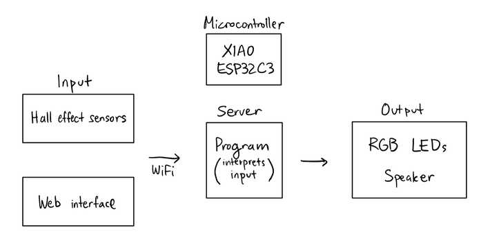
System Diagram
Baba Lamp Shade
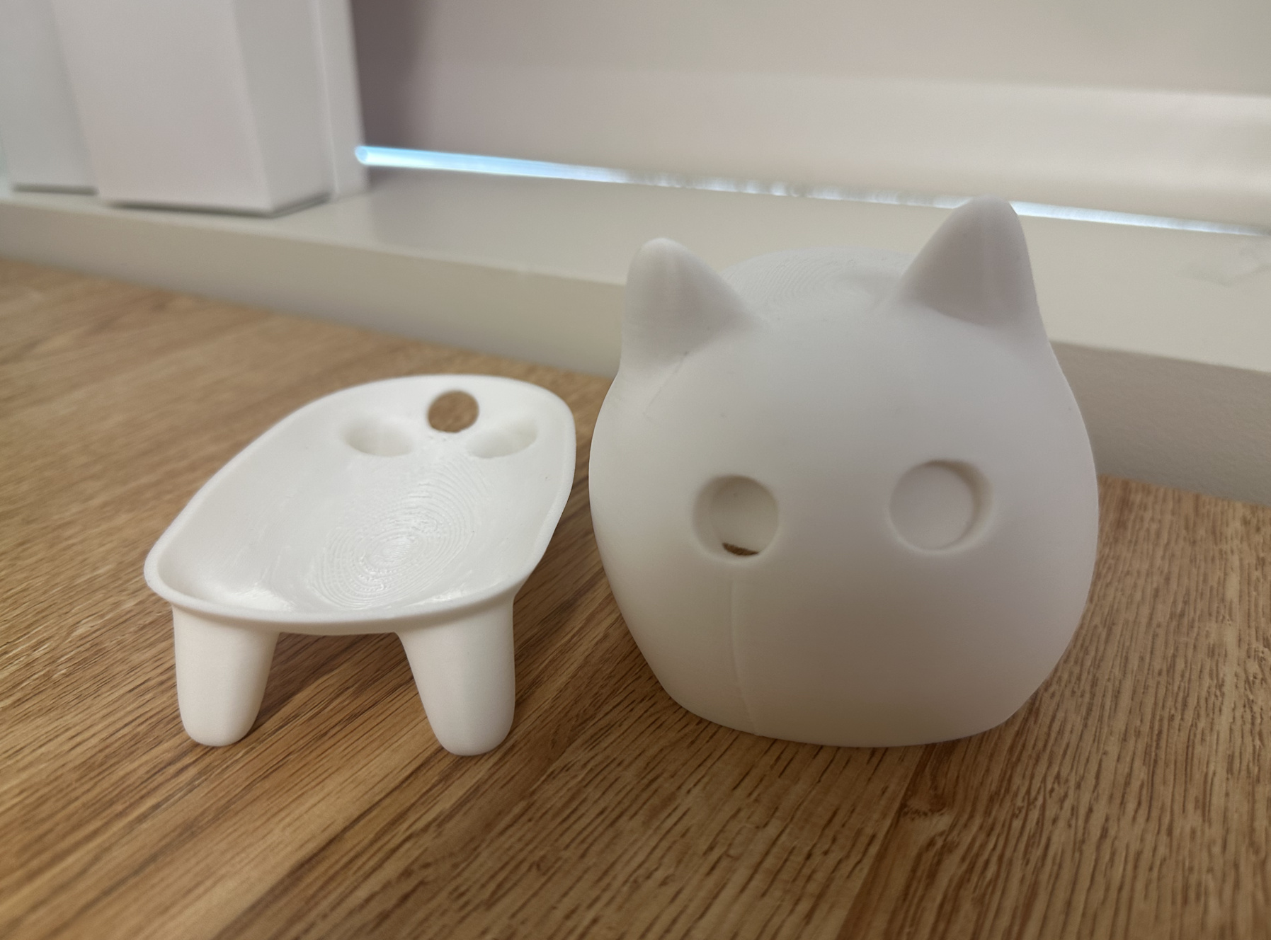
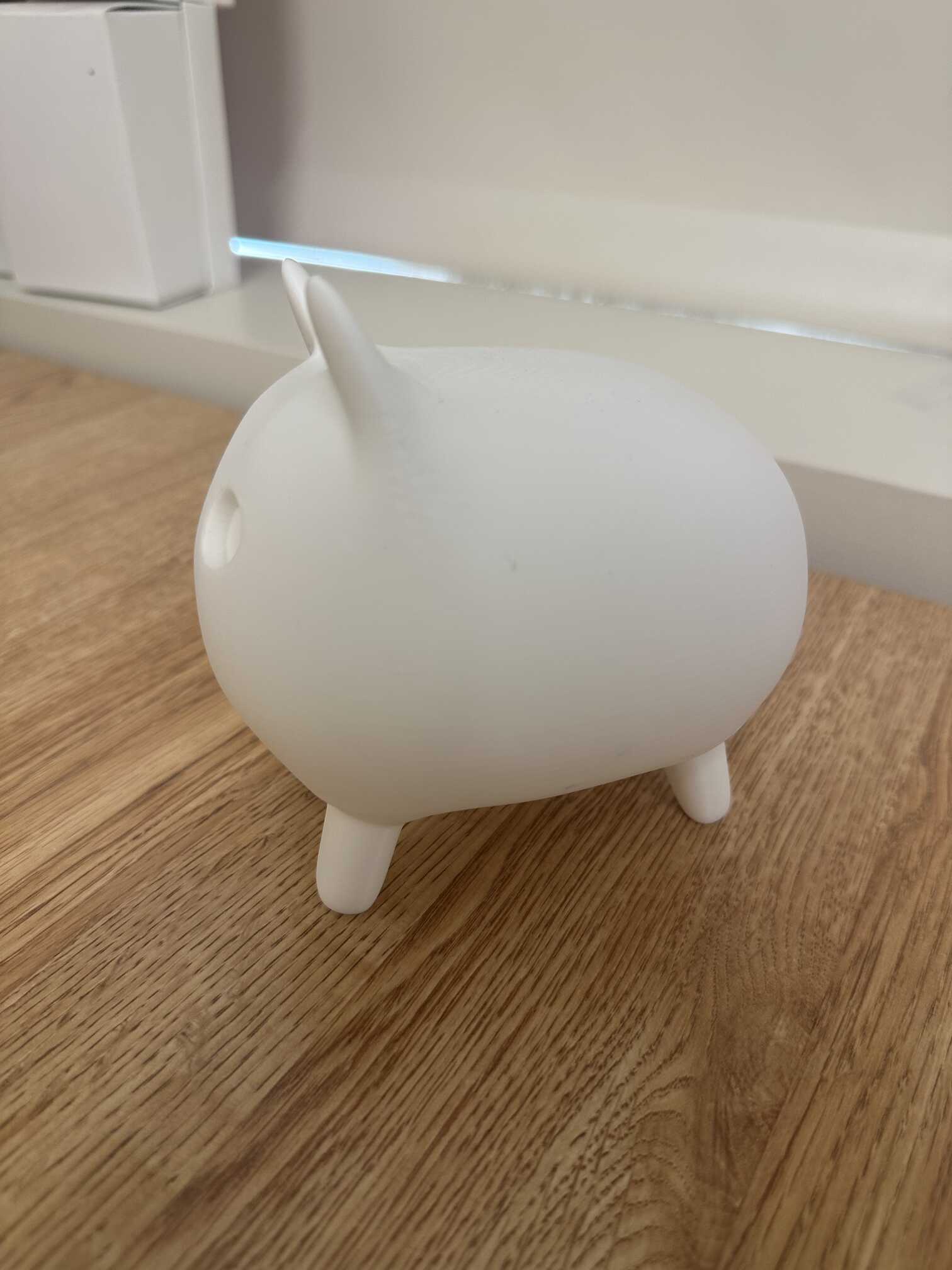
I found these STL files online. I scaled it up and created a hole in the back through which I can route cables using MeshMixer.

This print took quite long, around 3.5 hours for the top and 1 hour for the bottom. The top especially required a lot of supports.
Overall, I like how it looks! There is a seam in the front from where each layer ends, I wonder if there was a way to prevent that or place it in the back. I also wish I had come up with a better mechanism for keeping the top and bottom together-- maybe a platform with pegs and holes. For now, tape will have to do.
Puzzle Piece
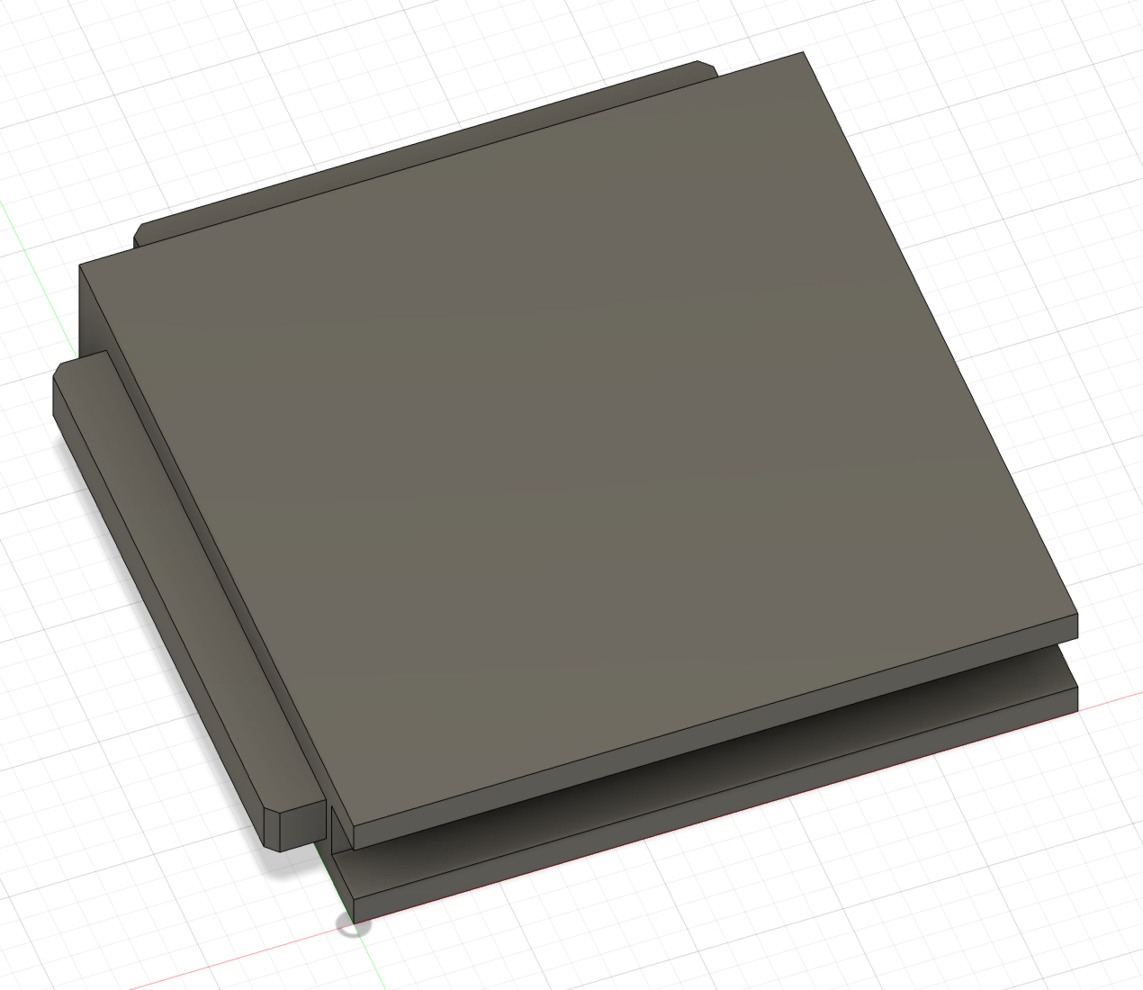
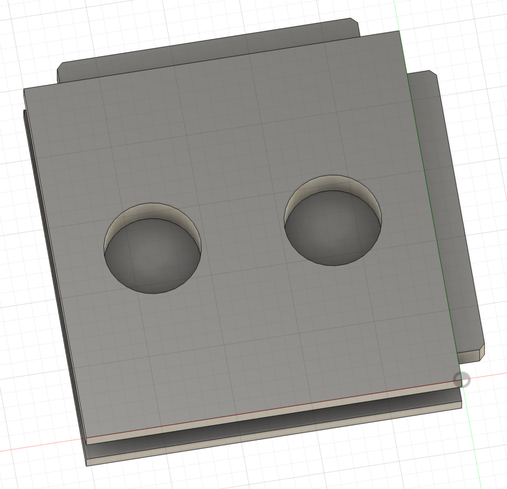
The puzzle piece will be square, with tabs on the top and left edges, and slots on the bottom and right edges. This will ensure that all puzzle pieces will be able to slide past each other.
Since the puzzle piece is square, it was actually not too bad to CAD. I first created a sketch, within which I created a rectangle. I constrained the sides to be equal so that it would be a square. I then extruded the sketch by the piece thickness, so that I had a 3D square piece. Then on each side face of the piece, I drew a sketch of the rectangle that would either be extruded outwards or inwards to form the sliding tracks. I extruded them.

I made sure to make everything parametric, so that I could easily change the dimensions of the piece, the magnet holes, the sliding tracks, and the clearances.
I had to iterate on the design a couple more times, as it was tricky to get the clearances just right. I started off with 0.01 in clearance (the slot is 0.01 in wider than the tab). The fit was way too tight. So I went up to 0.02 in. The top and bottom edges now slid past nicely, but the other edges did not. I suspect it was because of the way supports are printed differently for differing orientations. Finally, I went up to 0.025 in. This allowed all edges to slide past each other smoothly! I also gave the tabs chamfered corners to make it smoother.
I also made holes on the bottom for the magnets to be inserted into. I measured the diameter and thickness of the magnet using a caliper, and then made the diameter and depth of the hole a bit bigger than that to account for tolerance.
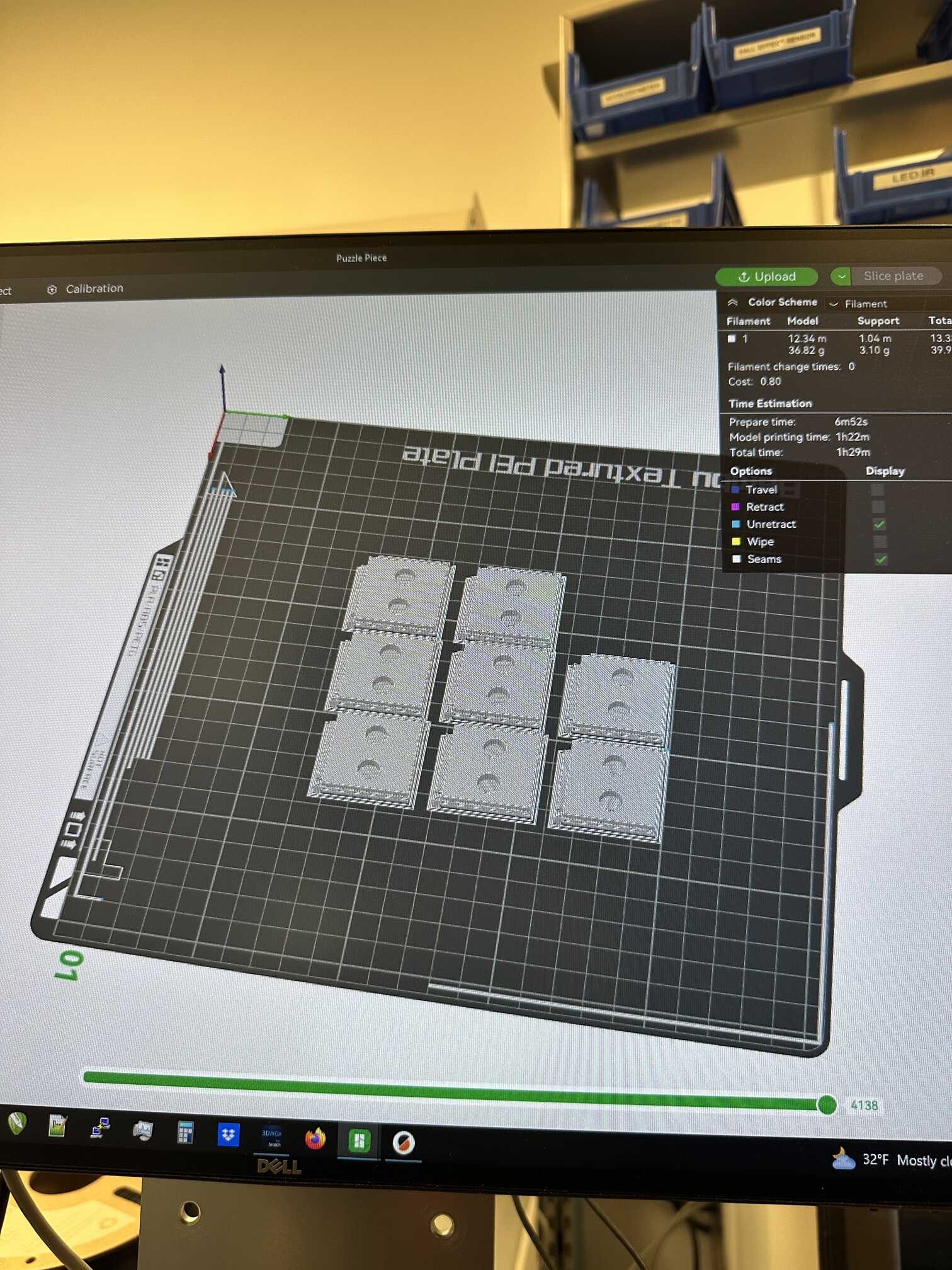
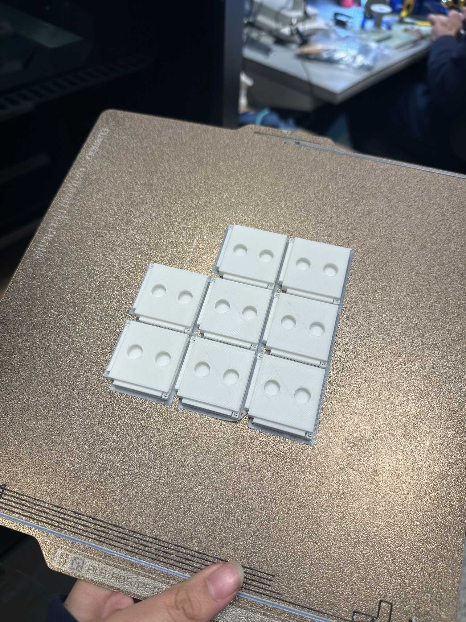
It was painfully annoying to get the supports out, especially the ones inside the slot. I used pliers. Here are the printed pieces:
Puzzle Board
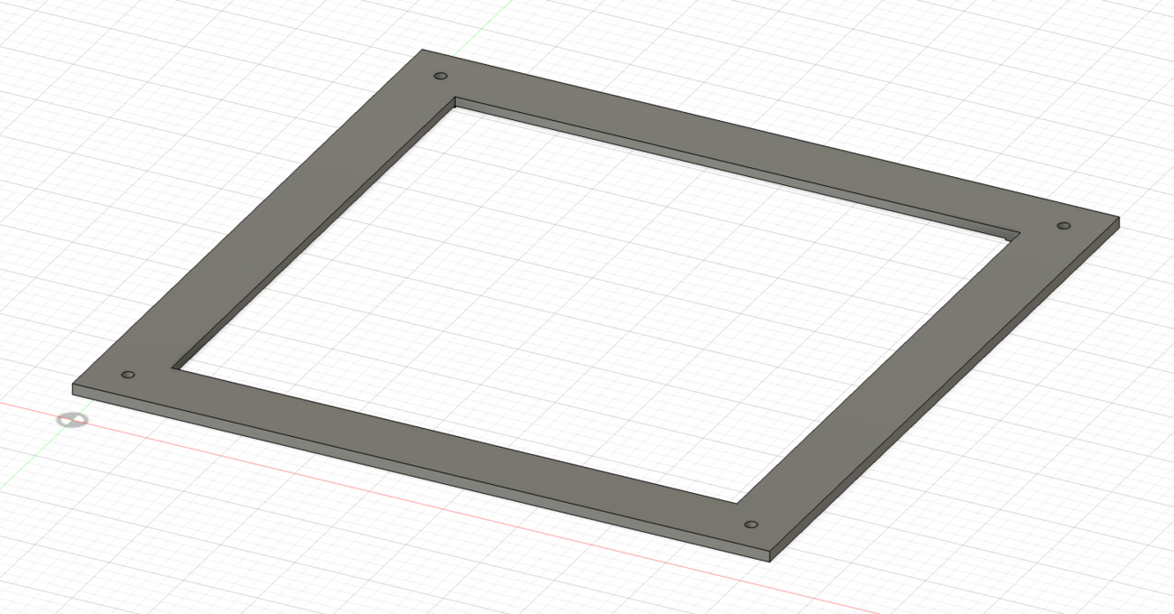
The CAD for the puzzle board followed a similar process as the puzzle piece. I first created a square, which I then extruded to form a 3D board. Then, within that square, I created a smaller square, which I extruded downward to cut out a cavity for the pieces to go in. Then on each of the inner side faces of the board, I drew a sketch of the rectangle that would either be extruded outwards or inwards to form the sliding tracks. I extruded them. Again, I made sure to make everything parametric. Here is the result:
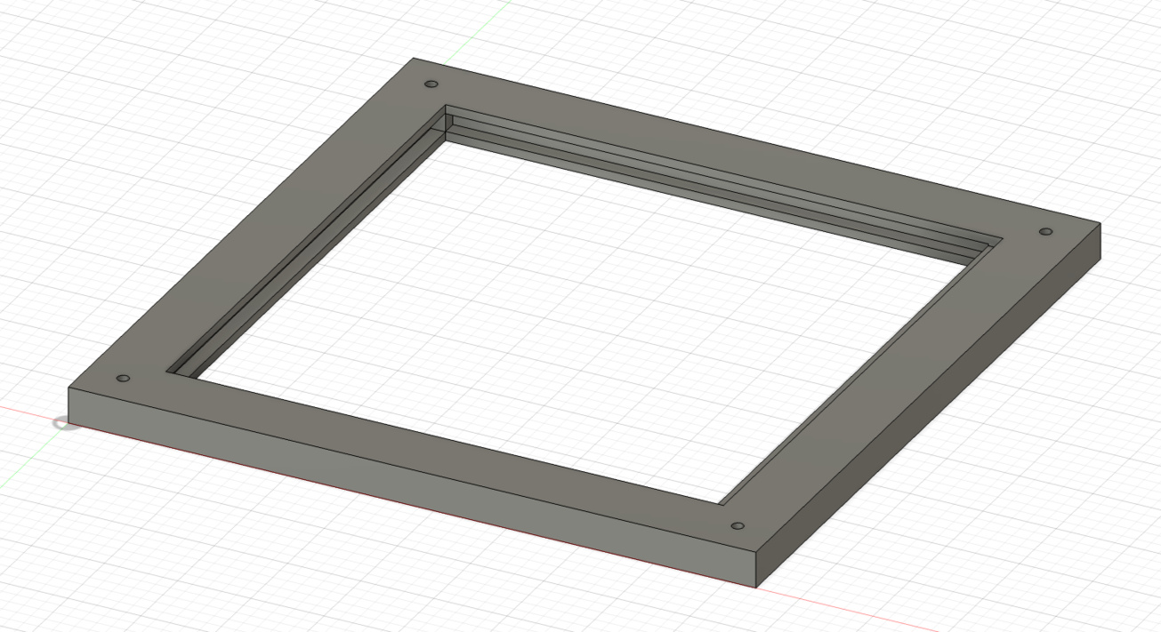
Unfortunately, I wasn't able to fit in the last piece on this board. Given the flexibility of the board and the clearances, I expected to be able to just pop in the last piece, but that wasn't possible. So I decided to split the board into two parts, top and bottom, so that I could first put down the pieces on the bottom piece, then screw on the top.
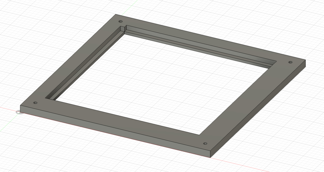
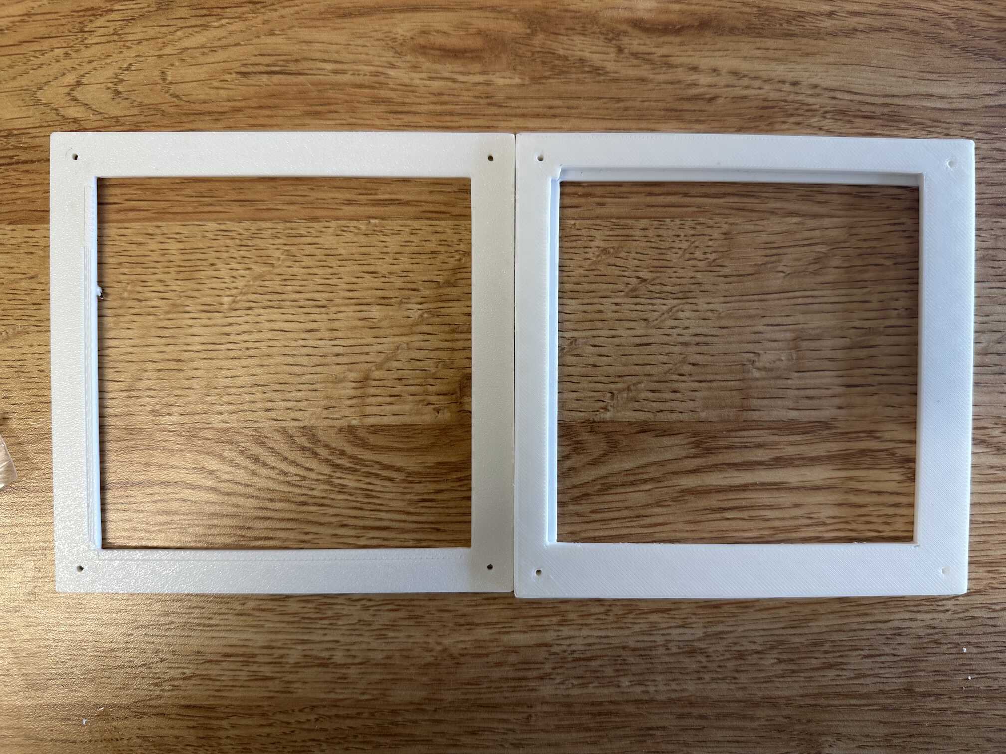
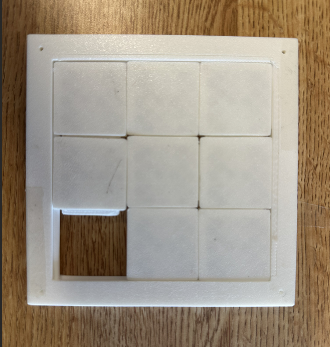
This worked much better! (insert video of sliding)
PCB
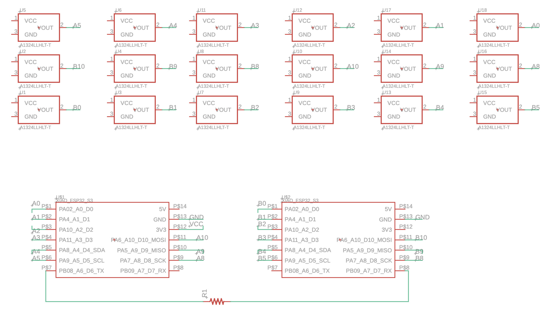
The puzzle board PCB consists of 2 XIAO ESP32S3s (to handle all 16 inputs) as well as 16 hall effect sensors. I considered multiplexing, but because it's only 16 inputs, Anthony suggested I just use 2 micrcontrollers to keep things simple.(Originally, I also had a capacitor in the design because I'd thought it was necessary, but Anthony pointed out that it is not.) Each hall effect sensor is connected to 3.3V, ground, and a GPIO pin. The TX pin of one micrcontroller is connected to the RX pin of the other (the former sends data to the latter). Here is the schematic:
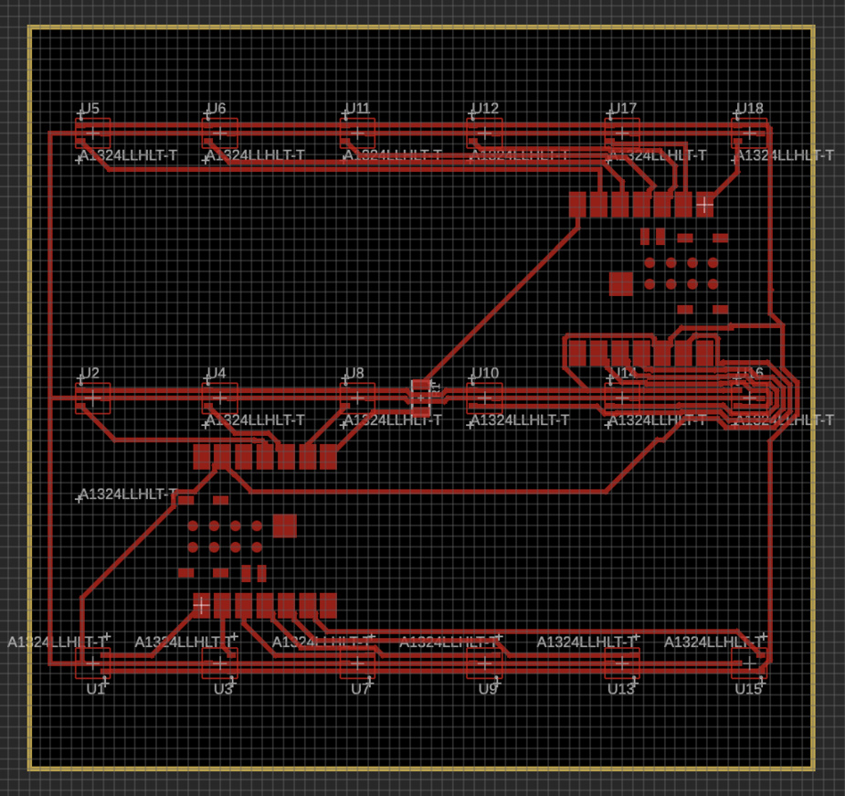
Routing was a bit tricky because I wanted to fit both micrcontrollers within the puzzle board. I used one 0 resistor to jump a trace. I also had to place the components at precise locations to match the locations of the tiles on the board using the Inspector tool. Here is the routed board:
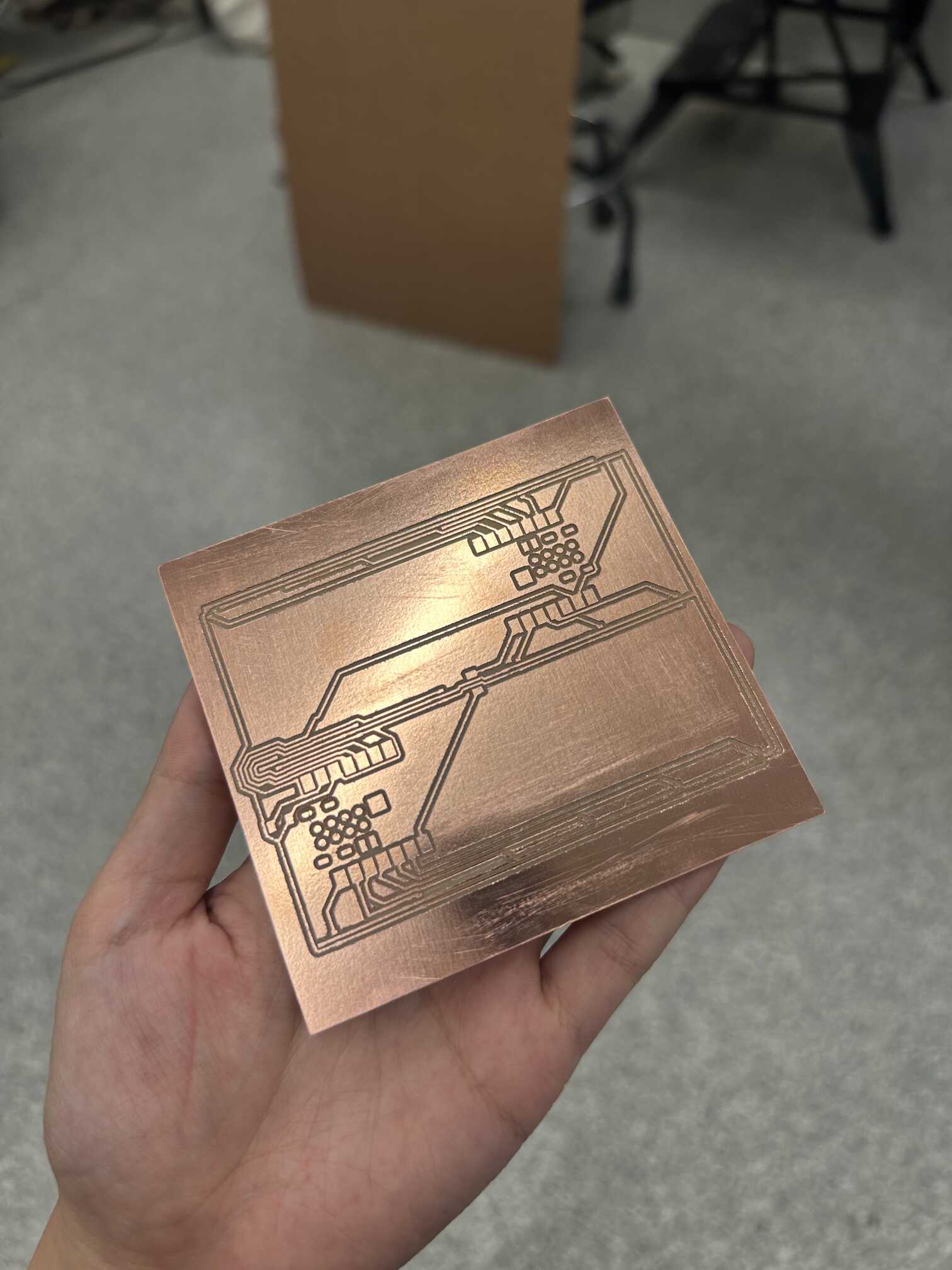
Milling took quite a while--around 40 minutes. I probably should have made the clearances on some of the routes a little larger, and it would have made the job faster. Here is the board:
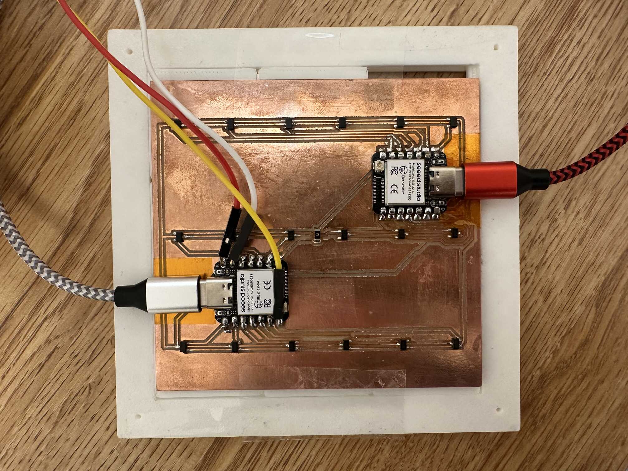
Soldering was also a bit tedious. I used solder paste and hot air for the hall effect sensors since they are so small, and it's easier to control the amount of solder with the paste. For the microcontrollers, I used the solder wire and soldering iron. Here is the stuffed board:
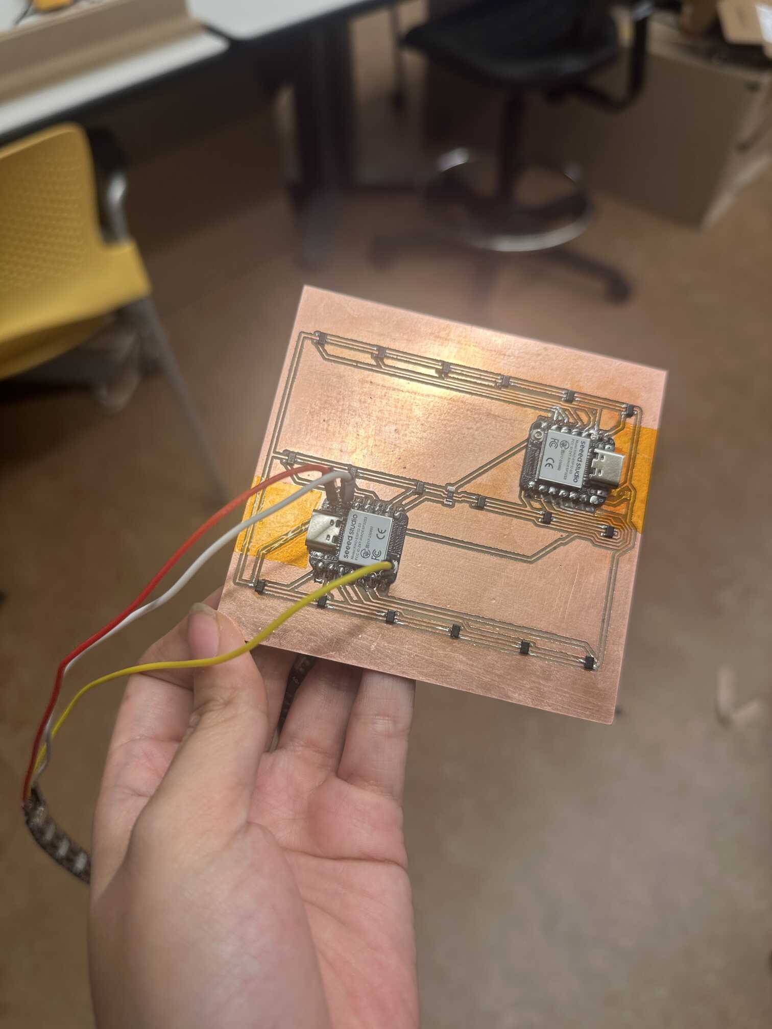
Unfortunately, I soon realized that there was a short in my board, as one of the micrcontrollers was not getting powered. It wasn't visible, but Anthony helped me test using the multimeter, and he suspected it was because some of the routes were so close. So, we removed the microcontroller (using hot air), removed the extra solder (using copper wick), placed some tape under it (to make sure no solder leaked), and then re-soldered the microcontroller. Now it works!
I also was initially getting a reading of 0 on one of the hall effect sensors. I soon realized that I didn't solder it correctly (one of the legs was floating), so I went back and re-soldered that.
Neopixel Strip
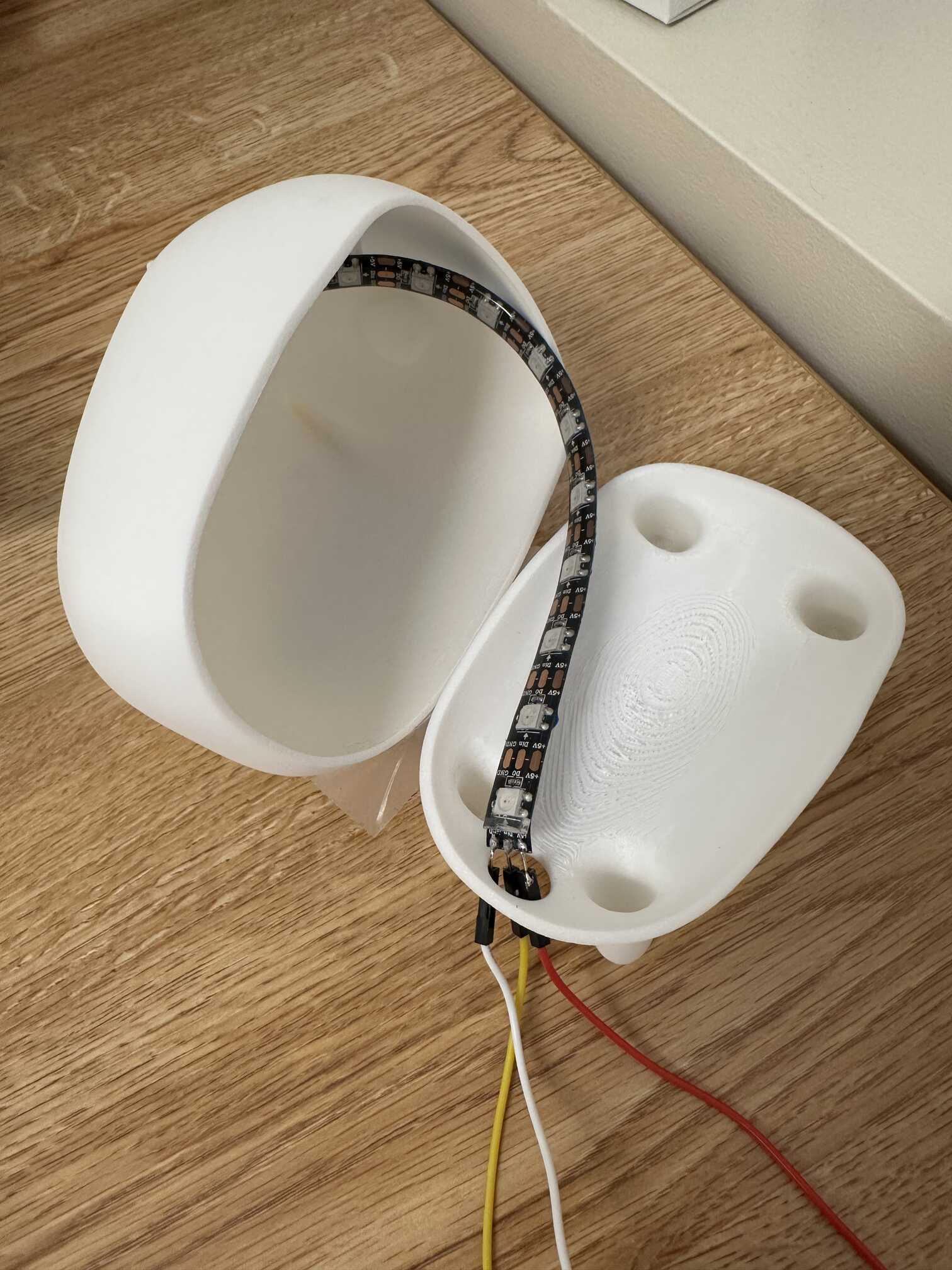
I had originally planned on making a separate board for the lamp and commmunicating wirelessly to the puzzle boards. However, due to time constraints, I decided to just connect it directy to the puzzle boards. So I soldered the Neopixel strip directly to one of the microcontrollers. I used the TX pin of the receiving microcontroler (since communication between the microcontrollers only needs to be only one-way) for input, and soldered the 5V and ground ends as well.
Encoding Each Tile
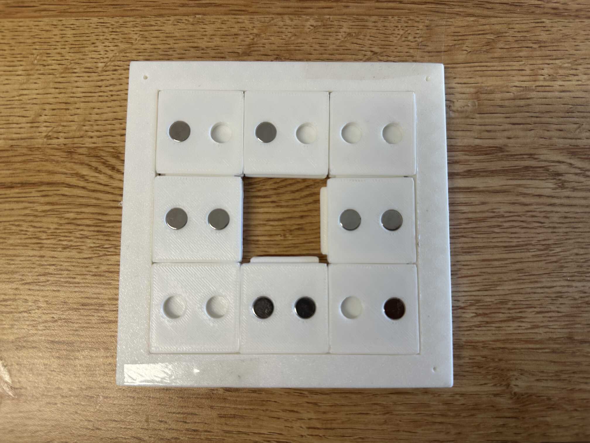
Each hall effect sensor acts as a bit. n hall effect sensors per tile position is able to encode 3^n possible distinct tiles (north, south, none) for each. Since I wanted to encode up to 8 tiles, I decided to go with 2 sensors/magnets per tile.
Programming
We're back in home territory! Programming was relatively straightforward and easy compared to the rest of this project. The most difficult part was communicating between the two micrcontrollers.
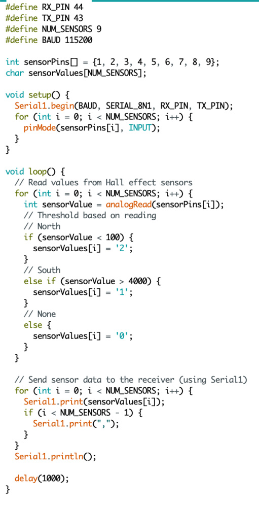
I programmed one micrcontroller to read the inputs from its hall effect sensors and transmit the data serially to the other microcontroller. I referenced the sample code on the SEEED website for serial communication. Essentially, we use Serial1 to send the data (and Serial for debugging).
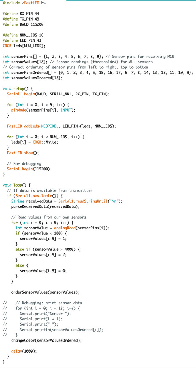
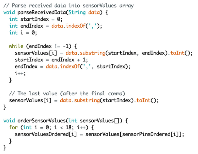
I programmed the second micrcontroller to read the inputs from its hall effect sensors and receive the sensor data from the other. The sensor data is received through Serial 1. We first check if there is any data available in Serial 1 by calling Serial1.available(), and if there is, we read the sensor data from the transmitter. The data is parsed by separating the string by the delimiting commas, and converting the characters into ints. Then, we read the inputs from this microcontroller's hall effect sensors. I thresholded the sensor readings in order to categorize into North, South, or no magnetic field, each corresponding to a number (1, 2, 0, respectively). It then orders the data into the proper order (left to right, top to bottom in the puzzle grid). Then, I reordered them to be in the row-wise grid order. Finally, we process the combined data (from all the sensors) by calling the changeColor function.
The changeColor function checks if the phrase "BABA IS" appears in any row or column, and changes the color if so. I created a 2x2 array of Strings for the tile encodings. Index i, j corresponds to i, j for the two sensors for that tile (0 for None, 1 for South, 2 for North). I also created a 2x2 array of CRGB objects for the color mappings. I iterated through each row and column and checked whether the first two words were "BABA" and "IS". If so, I changed the color to the color corresponding to the third word in the row/column.
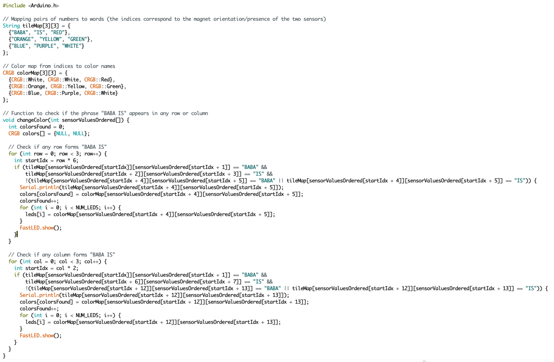
I used the FastLED library to change the color of the light strip. I iterated through every LED, changed its color, and then showed at the end.
Integration
Integration was not too difficult. I had a few hiccups along the way (e.g. I had to re-solder as mentioned above), but the code worked well.
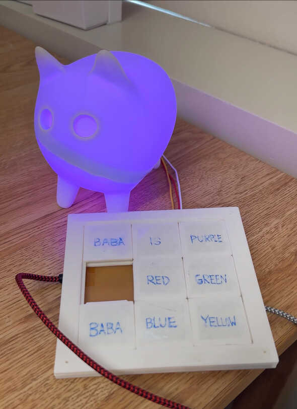
Demo
Miscellaneous
Who's done what beforehand?
People have made electronic sliding tile puzzles before. I'm not sure if anyone has ever used it to control a lamp.
Sources
- SEED page for XIAO ESP32-S3
- Thanks to JD (who did a similar project) for inspiration for the board design.
Evaluation
The project works! However, there are still some improvements to be made: making the puzzle slide more smoothly, making a bottom case for the PCB, adding more possibe rules, handling two rules at the same time, scaling up, adding an on/off switch, etc. One other oversight was that I didn't consider how the pieces would interact due to the magnets. Due to the proximity of the magnets and the ease of pieces sliding, some pieces would not stay in place due to other pieces' attraction/repulsion. Perhaps one way to fix this would be to make the pieces larger, so that the magnets can be further apart from each other, or make the pieces heavier so they don't move. In the future, I would also like to add more components such as a speaker or lock, and rules pertaining to those.
Files
- Puzzle Piece
- Puzzle Board
- Baba (Lamp Shade)
- PCB
- Code