Week 1: Computer-Controlled Cutting
Prior Experience: 3/5
I have used a Cricut vinyl cutter in Edgerton to make many stencils for glass etching. I have used a laser cutter exactly once as part of the Makerlodge orientation (I engraved an image from the Internet onto a piece of wood).
Laser Cutter
Joint Comb
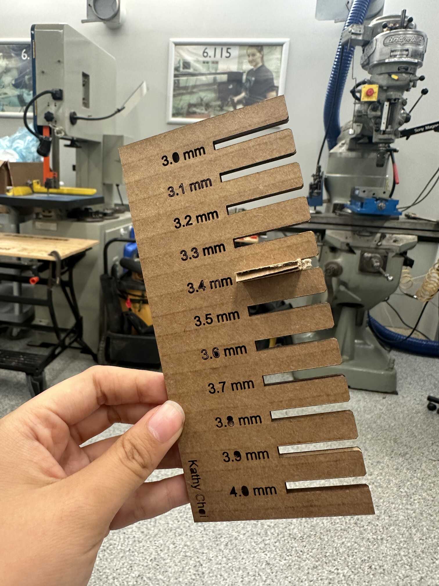
I created a joint comb to figure out the joint width that would work best. I tried chamfered joints ranging from 3.0 mm to 4.0 mm. Upon testing, 3.4 mm had the best fit.
The Idea
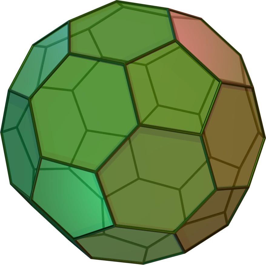
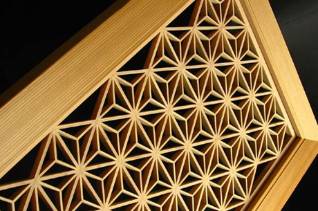
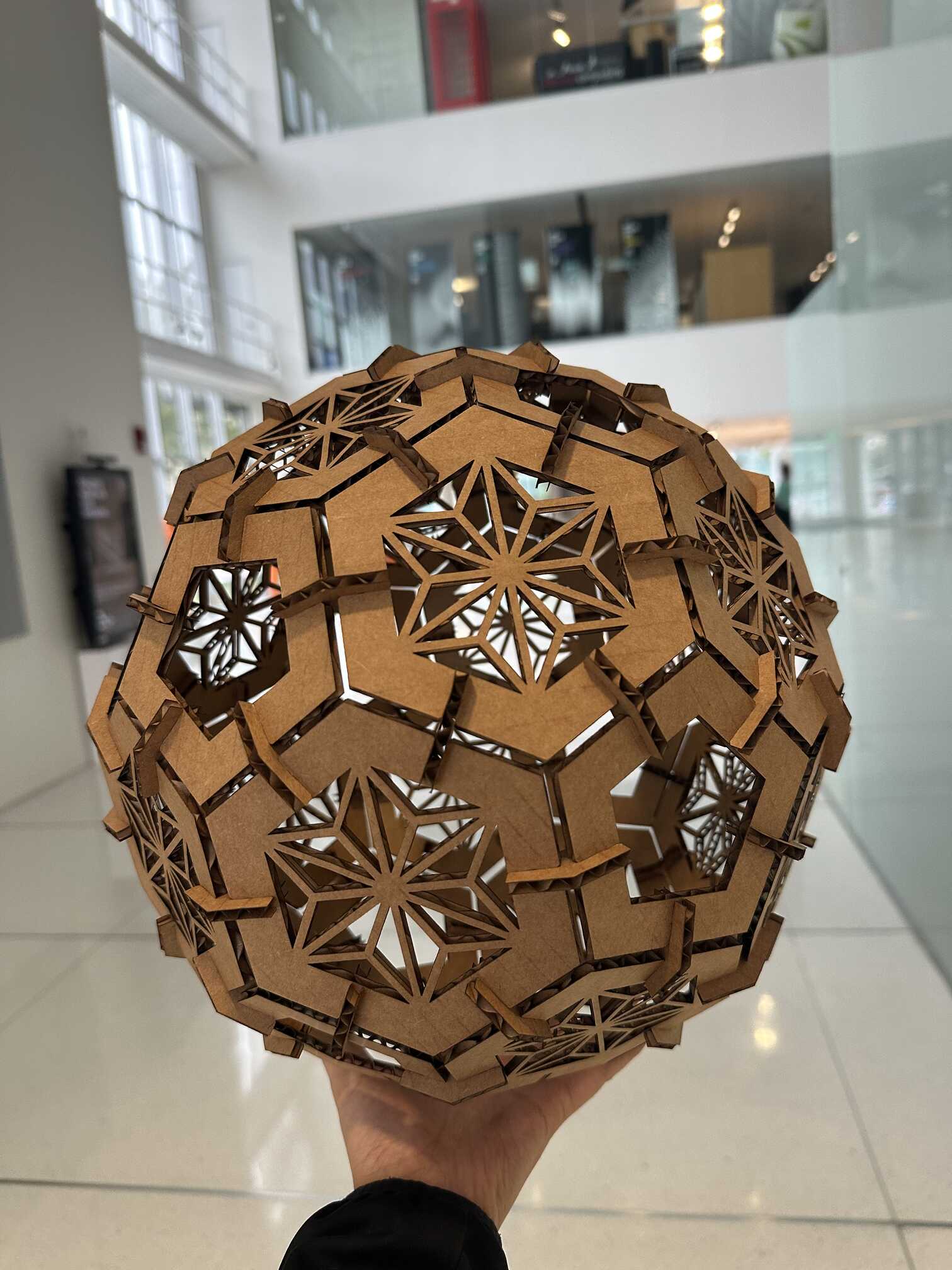
I wanted to make some kind of polyhedron, as I liked the idea of designing just a few pieces that I could make many copies of to build something pretty. Taking inspiration from past projects, I decided on a truncated icosahedron (like a soccer ball). It could potentially be used just for decoration, or as a lamp shade. For the design of the faces, I took inspiration from Kumiko woodworking patterns.
CADing
As expected, CADing proved to be difficult and time-consuming. Creating the base units and joints were not too hard, but creating the design for the hexagonal face was quite difficult.
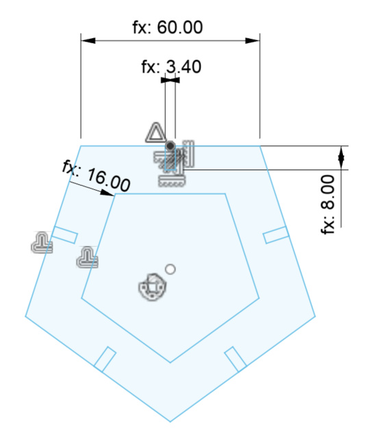
I first created the base pentagon and hexagon using the "Create: Polygon" tool. Creating the hole inside the polygons was easy using the "Modify: Offset" tool. I then created the joint slot by creating a rectangle, constraining one edge to be parallel to one edge of the polygon, and also constraining the midpoints of these edges to coincide. The constraints ensure that the slot is straight-on and at the center of one side of the polygon. Once I created one slot, I used the "Create: Ciruclar Pattern" tool to make a copy of the slot on each side of the polygon.
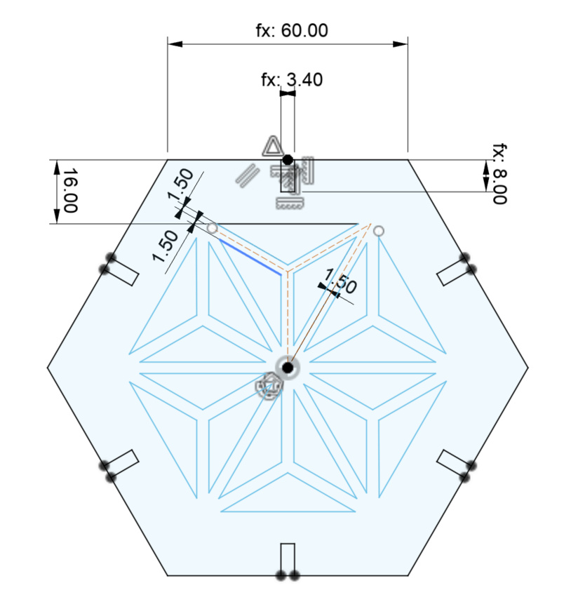
By far the most difficult part of CADing this project was creating the design inside the base hexagon. While it was easy to use lines to create a basic line-art-style design, it was difficult to give the lines thickness. I ended up drawing the basic design using construction lines, and then using the "Modify: Offset" tool to add a line on either side of each center construction line. Not sure if that was the best way to do this, but it worked. One other difficulty was making sure that the design connected with the frame of the hexagon. After a lot of failed attempts at using constraints to do this, I ended up just trimming lines that were too long. This was probably not the best way, as it removed some of the constraints for the frame of the hexagon. As before, I used the "Create: Ciruclar Pattern" tool to make a copy of the design on each side of the polygon.
I then designed the joints. I needed to design two joints with different angles since the dihedral angle between two hexagonal faces and the angle between a hexagonal/pentagonal face is different. I first drew the top edges of the joint by creating two lines at an angle of 138.18 degrees (the angle between two hexagonal faces). I then drew the sides such that they were perpendicular to the top lines. Finally, I drew the bottom edges such that they were perpendicular to the sides. Since everything was designed parametrically, it was super easy to just change the angle to 142.62 degrees (the angle between a hexagonal/pentagonal face) to make the second joint.
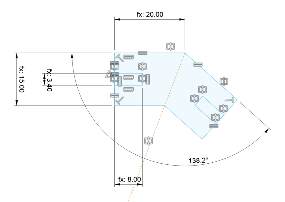

I then designed the joints. I needed to design two joints with different angles since the dihedral angle between two hexagonal faces and the angle between a hexagonal/pentagonal face is different.
Parametric design made things a lot easier. For example, I was able to design everything without knowing the joint tolerance and kerf, and then just change those values once to make the whole design compliant. Thee parameters I used were: kerf, slot_width/slot_height (dimensions of slot in joint), side_length (side length of a face), joint_width/joint_height (dimensions of joint piece), chamfer (size of joint chamfer), design_width (thickness of design). Looking back, I probably could have made it more parametric by defining the dimensions of the joint piece in terms of slot_width and slot_height.
Cutting
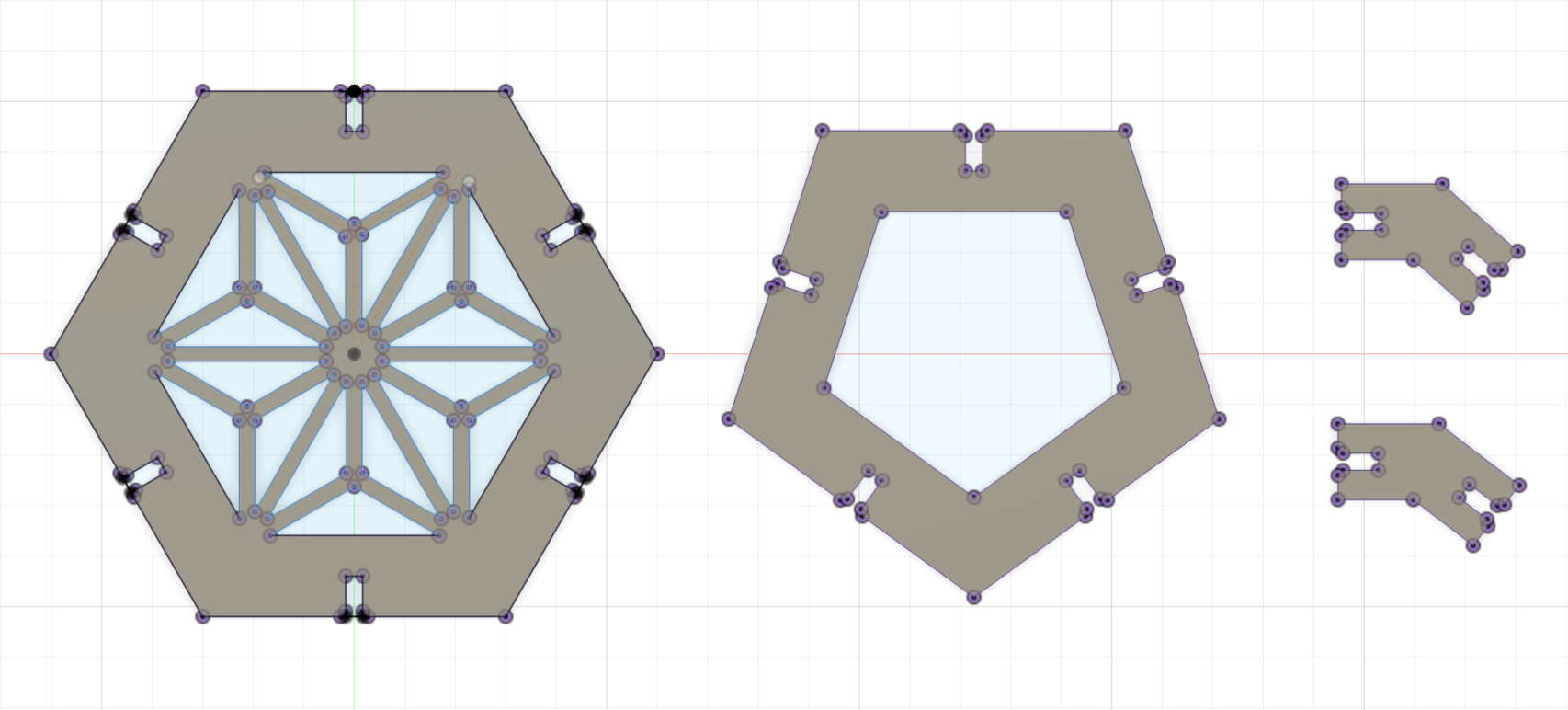
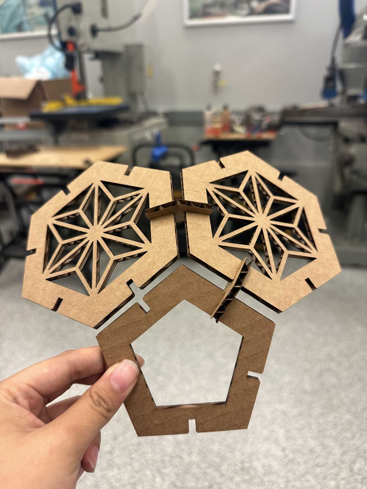
The whole time I was really worried about setting the place on fire (which I think means the staff did an effective job of scaring us into being cautious). First, I test-printed one each of the hexagon, pentagon, and the two joints to make sure that the pieces fit together well. I was quite happy with how it turned out! The joints fit together well. However, I wanted the gap between the faces to be a bit smaller, so I adjusted the length of the joint piece.
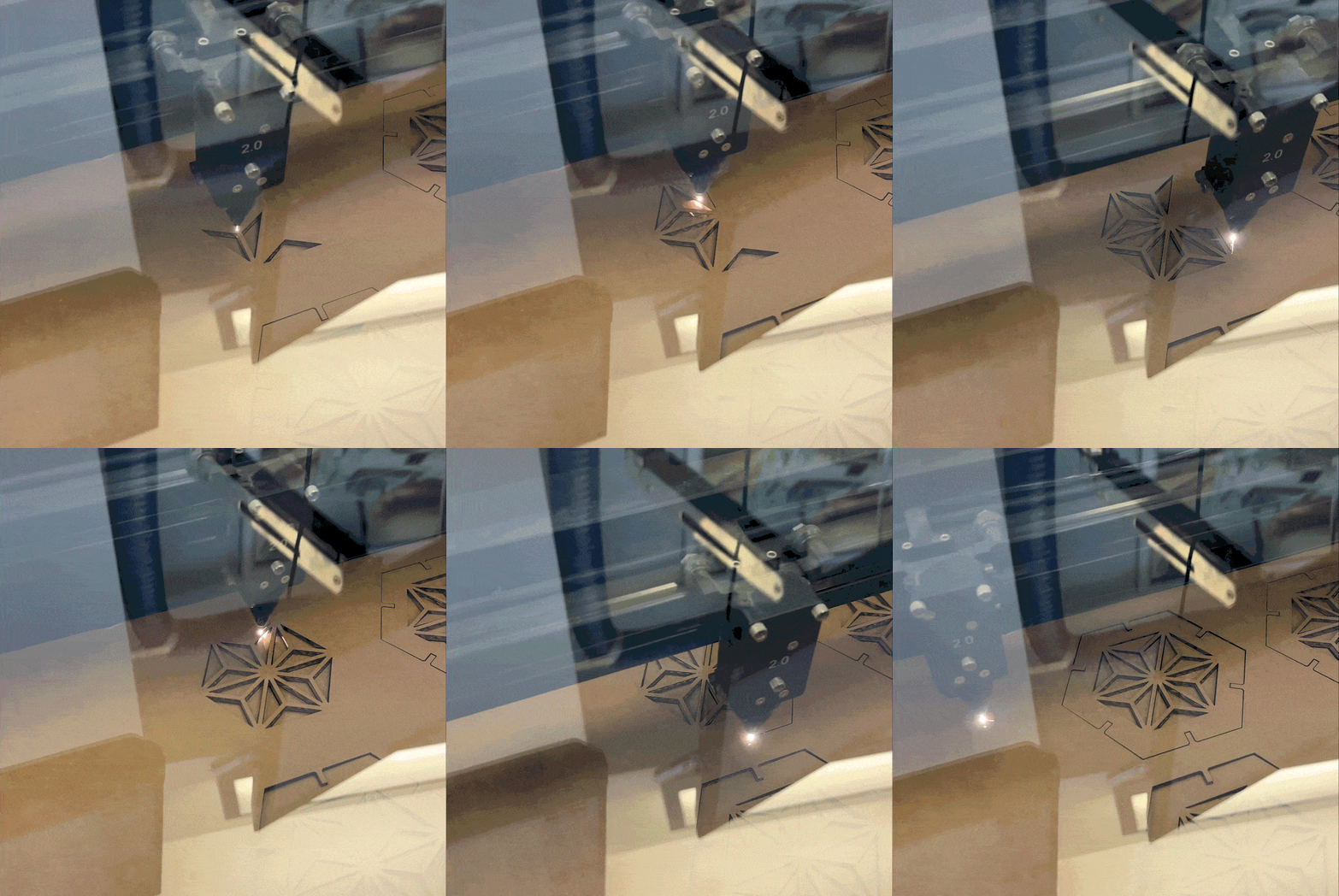
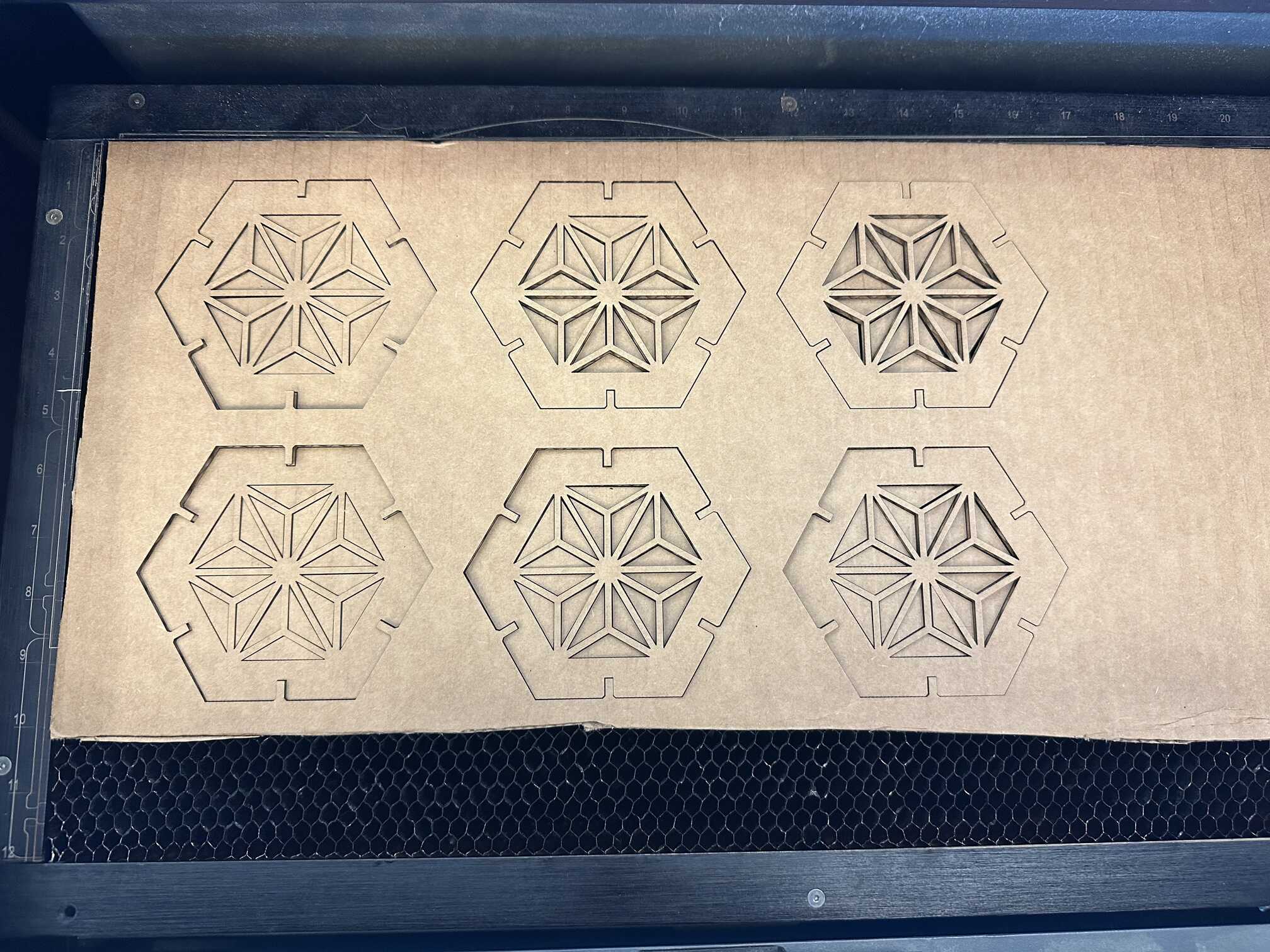
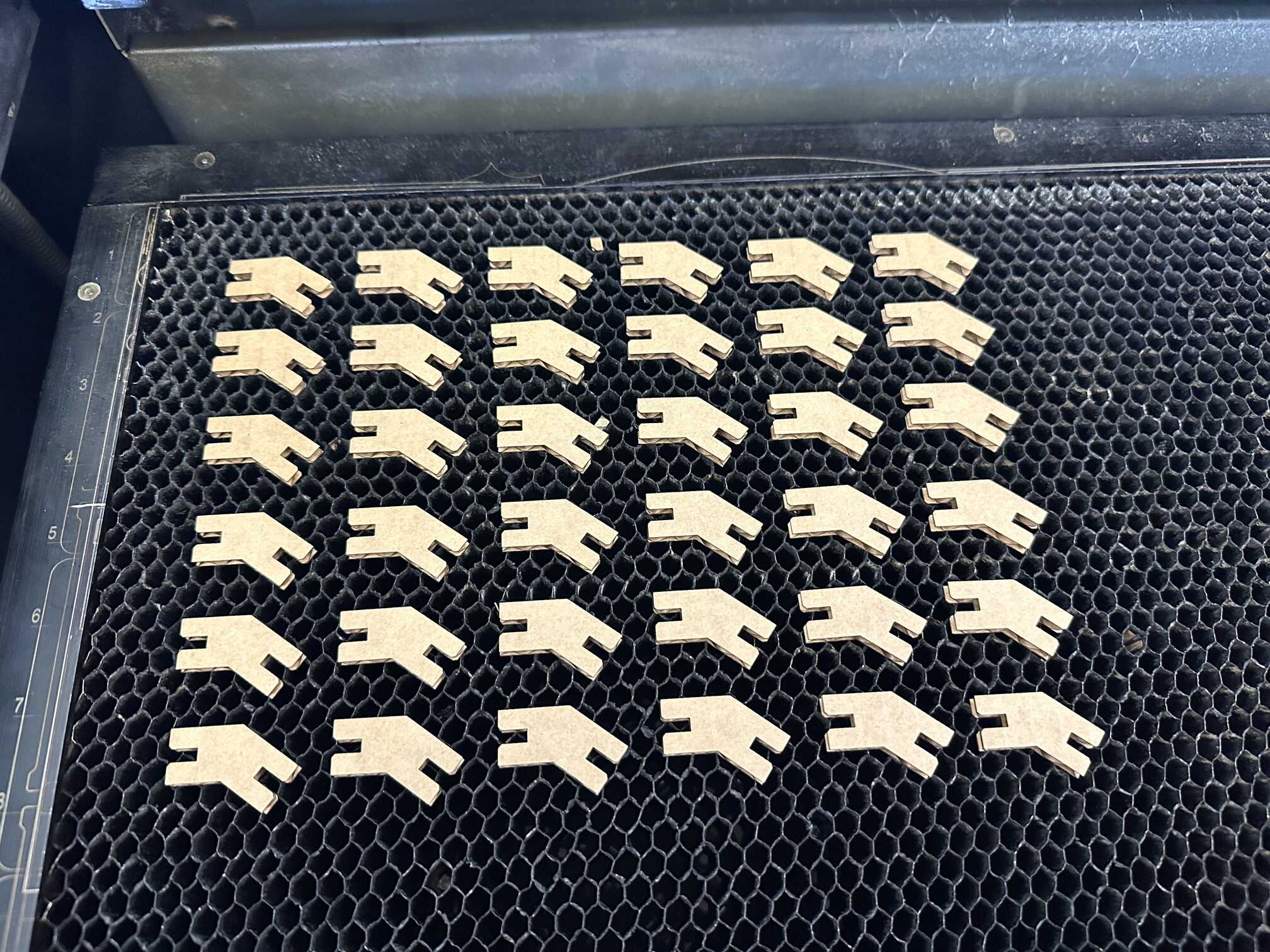
Once I had my final design ready, I got to mass-producing the pieces! It was a bit annoying to use CorelDRAW to make copies of the pieces, especially making sure that I didn't have any extra copies of lines (copy/pasting a sketch places the copy right on top of the original). Since I was using the smaller laser cutter, it took me around 8 prints to print everything.
Assembly
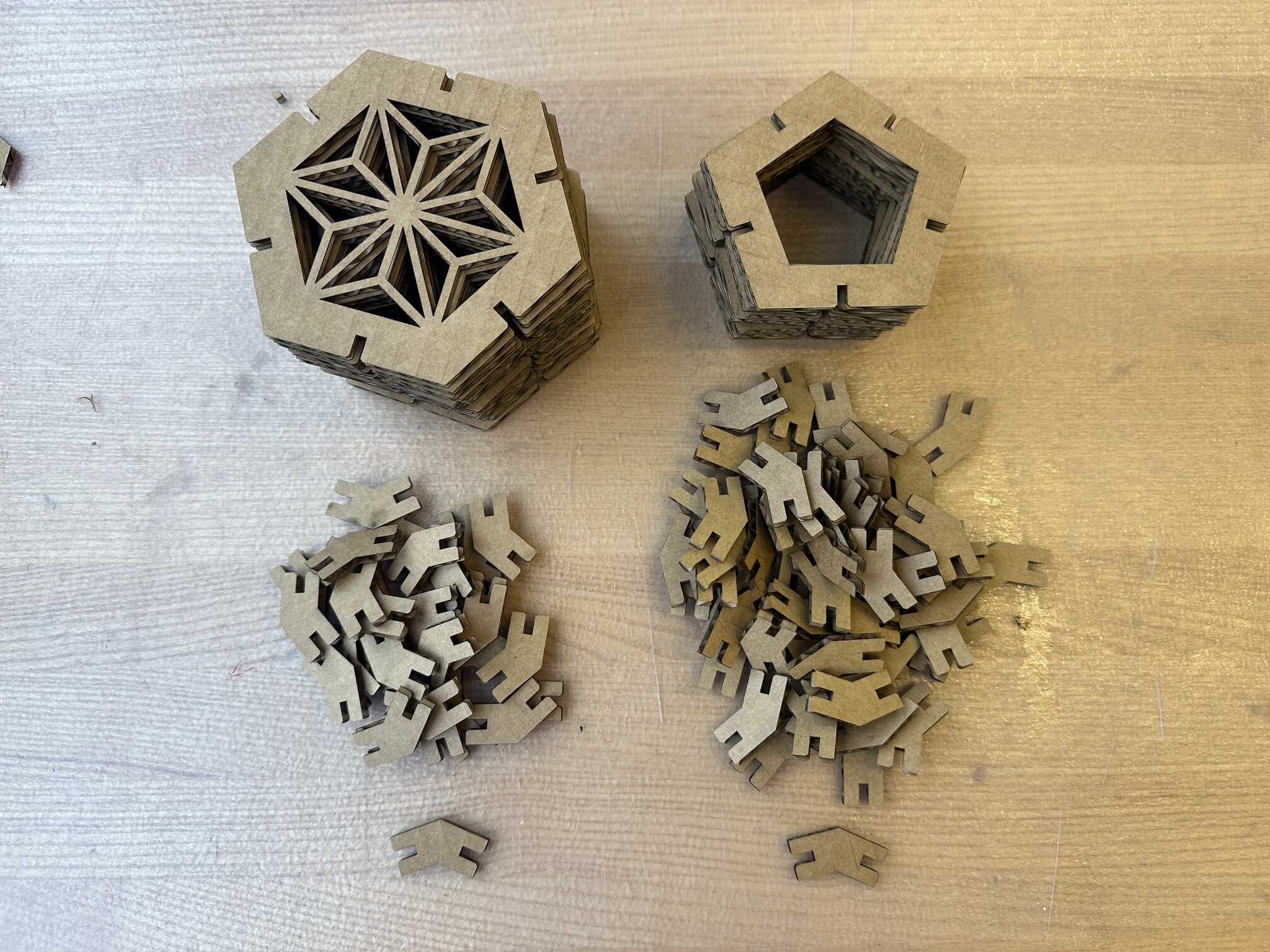
I way underestimated how time-consuming and difficult assembly would be. Some joints were tighter than others, possibly because the cardboard had uneven thickness at the edges. The first few pieces were easy, but it got progressively harder, as I had to join a face to 3-4 faces at once, and the cardboard was quite fragile. An hour later, it's done! I didn't fit the last piece because I want to leave an opening for a light bulb. Overall, this whole process was very difficult, but I think it was worth it! I really like how my lamp shade / ball turned out.
Vinyl Cutter
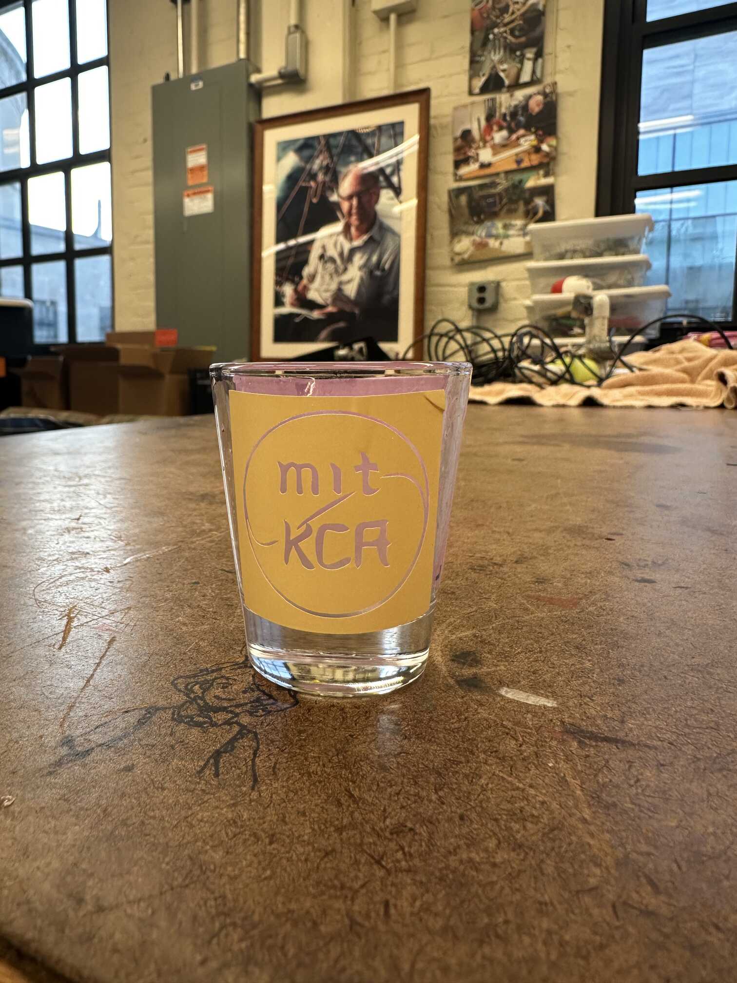
I cut a vinyl sticker of my club's logo. I used the Cricut vinyl cutter inside the Edgerton Center makerspace. This process was fairly straightforward. I first used Adobe Illustrator to trace the lines in the logo and convert to an svg (vector format).
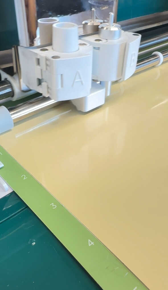
I then uploaded it to the Cricut software on my laptop, where I resized and positioned my logo. vinyl cutter. To prepare the vinyl cutter, I first stuck the sheet of vinyl onto a slightly sticky mat, smoothed it out, and then loaded the mat into the machine. Then I hit "Go" and it started cutting away!
Here is the result! I plan to use the vinyl sticker as a stencil for etching glass!
