Week 4: Electronics Design
Prior Experience: 0/5
Going into this week, I didn't even know what a PCB was. I have absolutely 0 experience designing or producing electronics. I am very scared.
The Idea
This week, I also wanted to start off with something simple because I'm completely new to electronics design. Building off of my assignment from last week, I decided to design a simple breakout board with an ESP32C3 microcontroller, a button, and an RGB LED. Breakout pins allow the pins on the microcontroller to be used, even after it has been soldered to the PCB.
Schematic
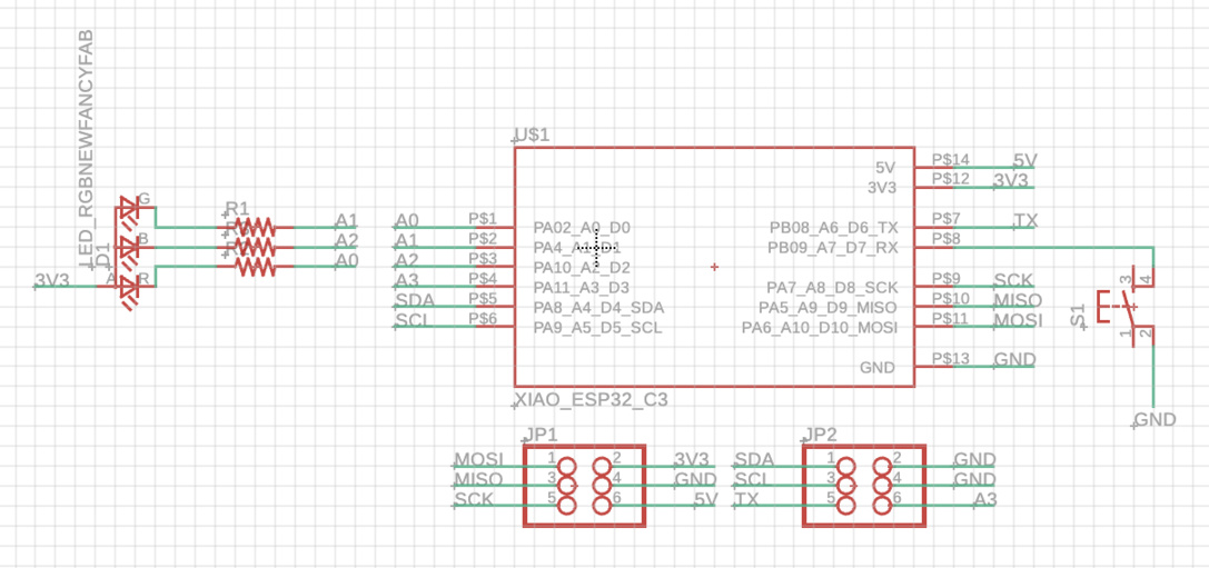
Even just designing the schematic was super confusing. I was very confused on whether I needed resistors and/or capacitors, and if so, where? Again, I'm not very good with circuits and EE stuff. I learned that the LED would need resistors to prevent burning it out. Initially, I was also very confused on what kind of connectors to use for the breakout pins. Turns out it doesn't really matter. I learned that I should seek out help earlier, because I wasted a lot of hours pondering very simple questions. Here is my very simple schematic:

Routing
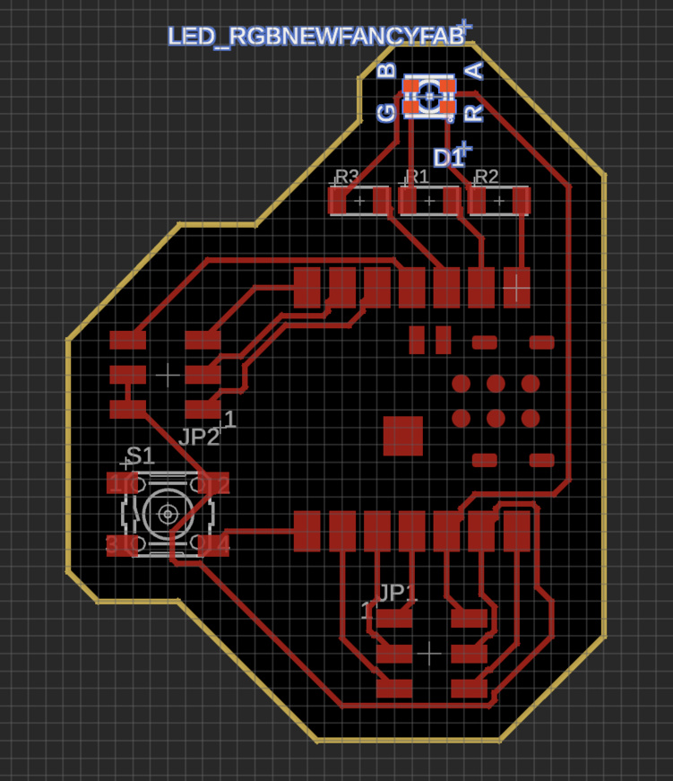
Routing seemed like the phone game "Flow", so I thought this would be the fun part... but boy was I wrong. First, I uploaded the DRC from the Fab library, which set the rules for trace width, clearance, etc. When I started routing, I realized that the pin locations on the schematic don't match up with the actual pin locations on the microcontroller. This led me to have to redo a bunch of the breakout pin connections on the schematic, so that the routes wouldn't intersect. After a lot of painful rotating and rearranging, this was the result:
