Final Project — HardWear: Cyber-Organic Jewelry Line
Modeling and planning HardWear: Cyber-Organic Jewelry Line
Latest update: Progress Log
📝 Progress Log
A living log of ideas, trials, and updates. Newest entries appear first.
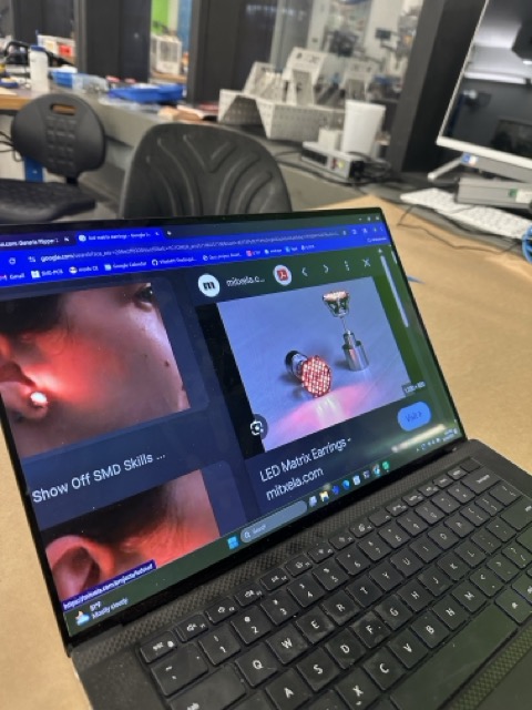
Project Video
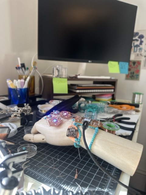
Lots of soldering.
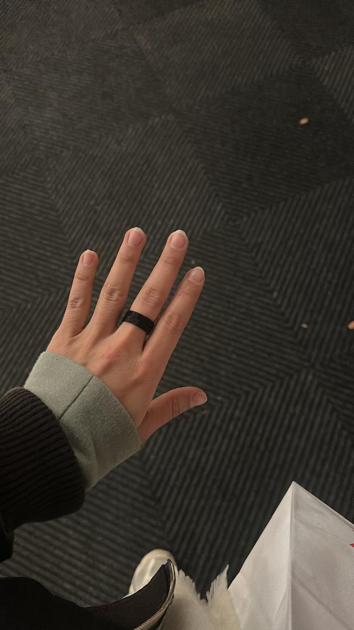
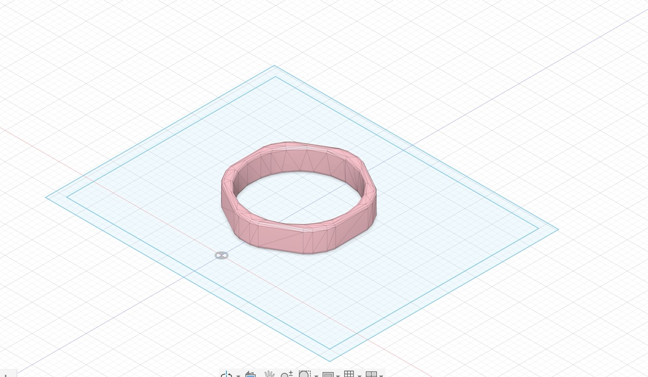
Conductive Ring for Capacitive Touch Control
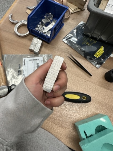
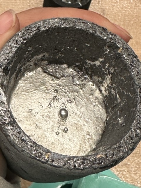
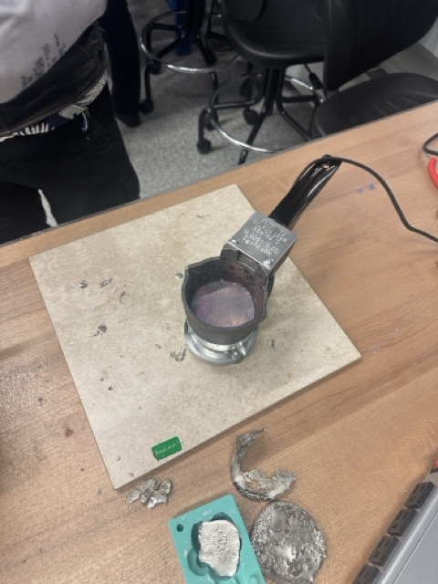
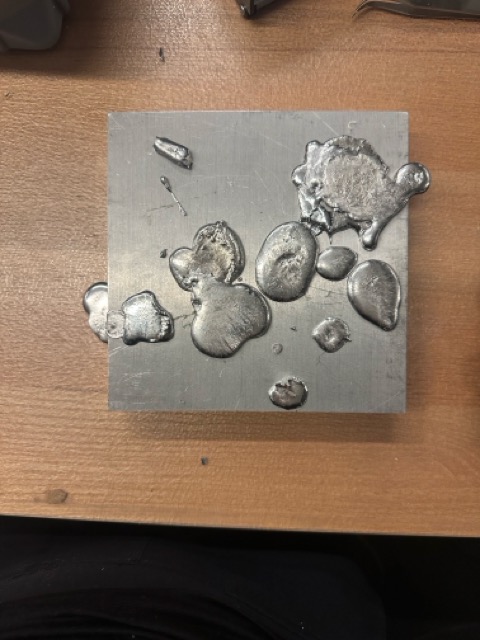
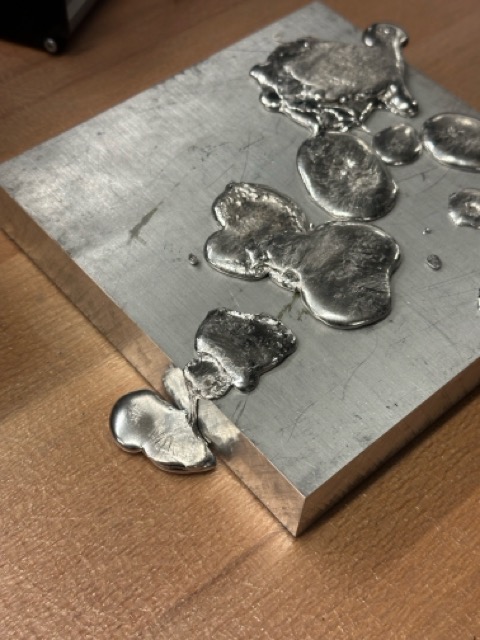
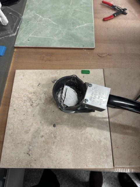
I initially attempted to metal cast a ring using a 3D printed mold. However, I discovered that investment casting was needed for this process, and the shop didn't have the facilities for that.
Instead, I pivoted to 3D printing a conductive ring using conductive filament. This ring connects to the capacitive touch pins in the ESP32-S3. I have two connectors for it, allowing it to function as a control button/reader.
Final Push for Final Project
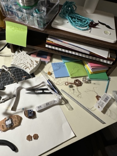
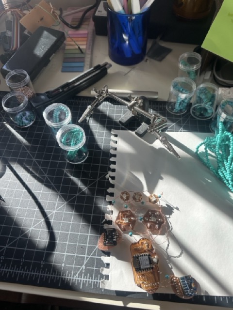
I started this project by visually designing the jewelry piece, laying out elements first through sketches and then arranging them physically on paper. My initial intention was to explore jewelry as a system, not just an object—something modular, electronic, and wearable.
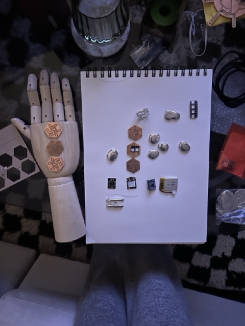
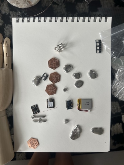
Early on, I experimented with metal casting to test the limits of what could work as beads and structural elements. Through this process, I realized that the surface area was too small to meaningfully integrate electronics in the way I wanted. That realization became a turning point.
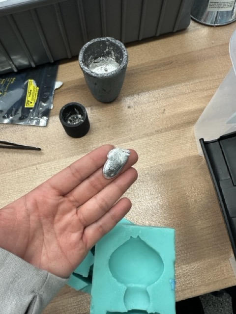

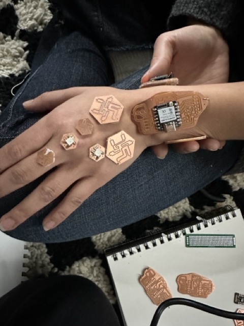
Instead of forcing electronics into traditional jewelry forms, I decided to turn the electronics themselves into the beads.
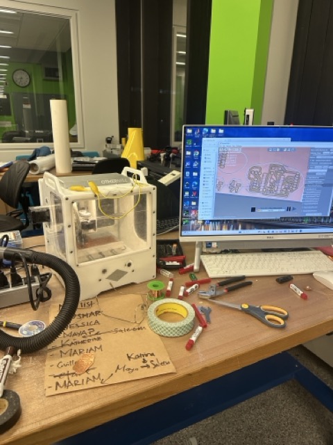
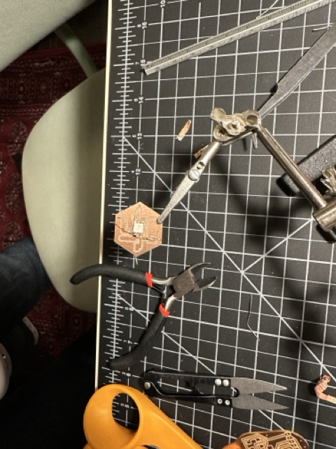
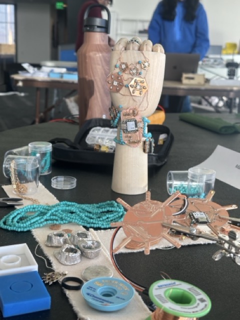
PCB Design + Form Exploration
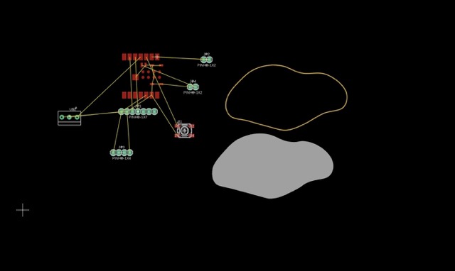
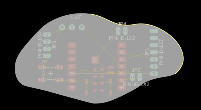
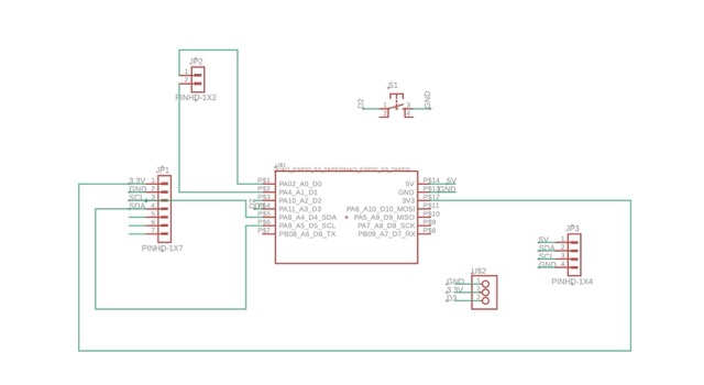
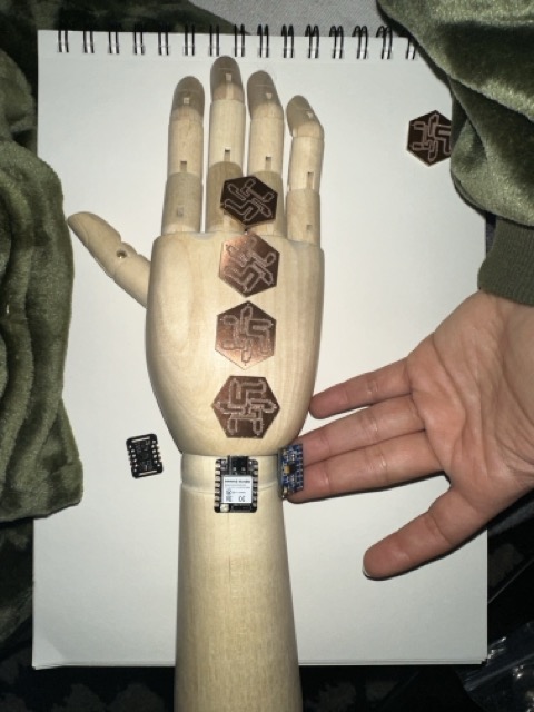
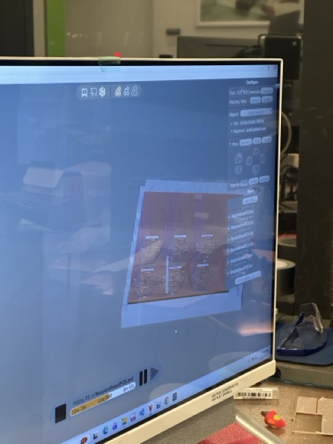
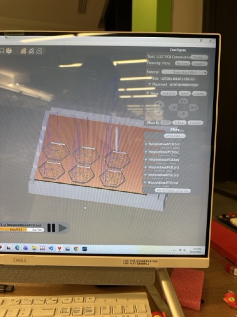
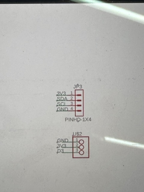
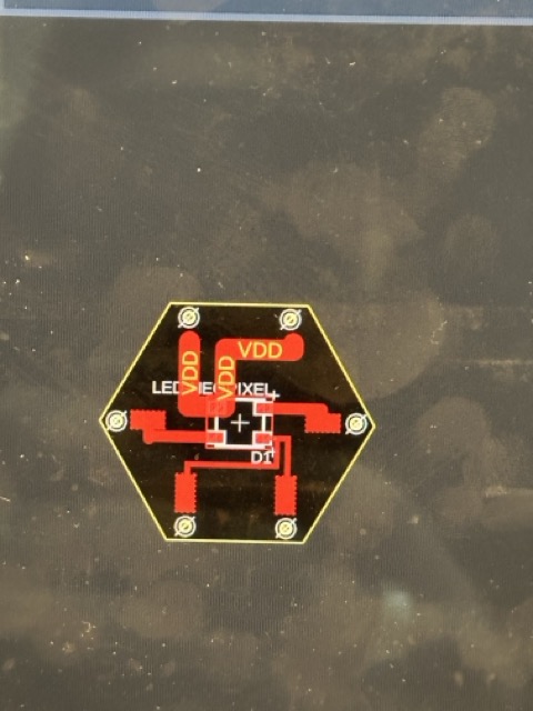
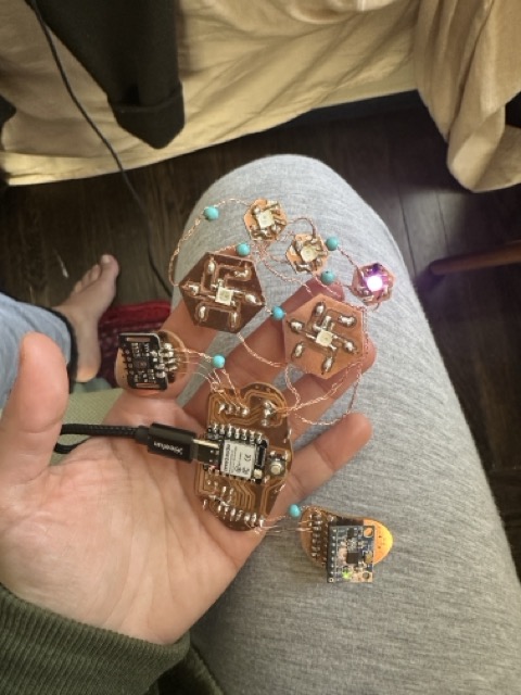
I redesigned the concept around PCB-based LED beads. I created the schematic and decided to work with hexagonal board shapes, which allowed for modularity and repetition while still reading as jewelry.
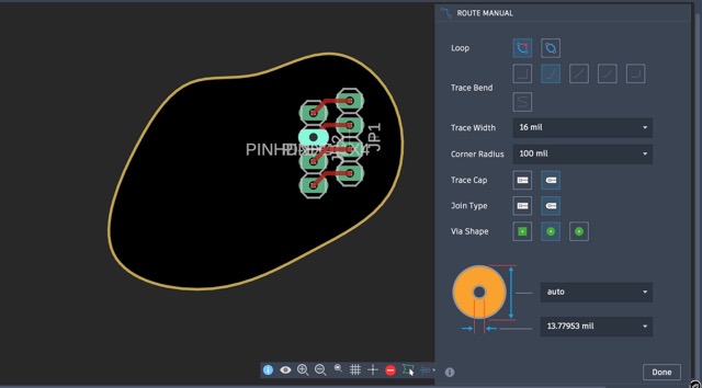
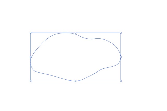
To explore more organic forms, I also experimented with blobs using:
- Blob Creator
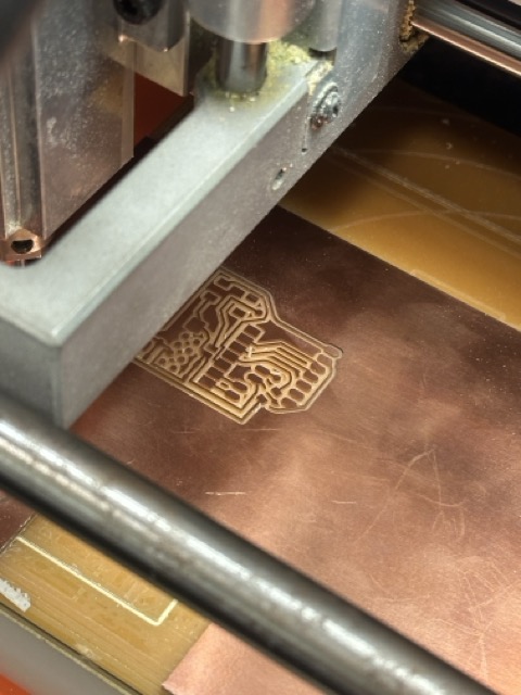
- Adobe Illustrator
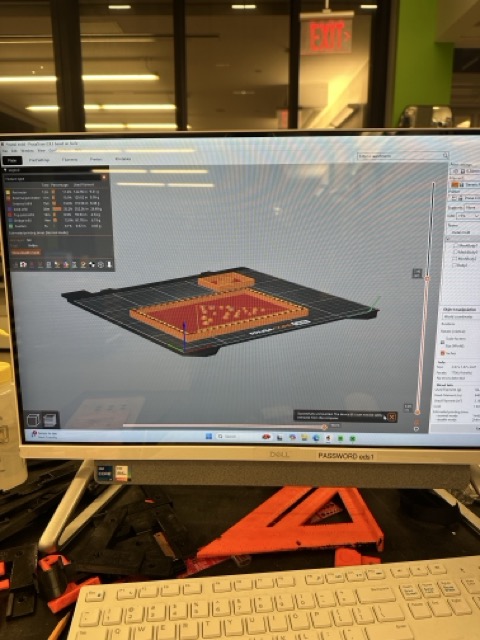
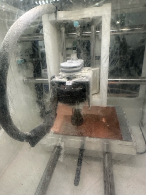
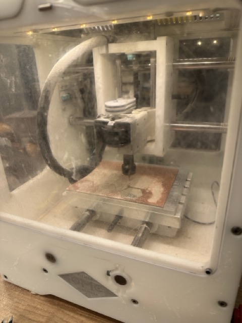
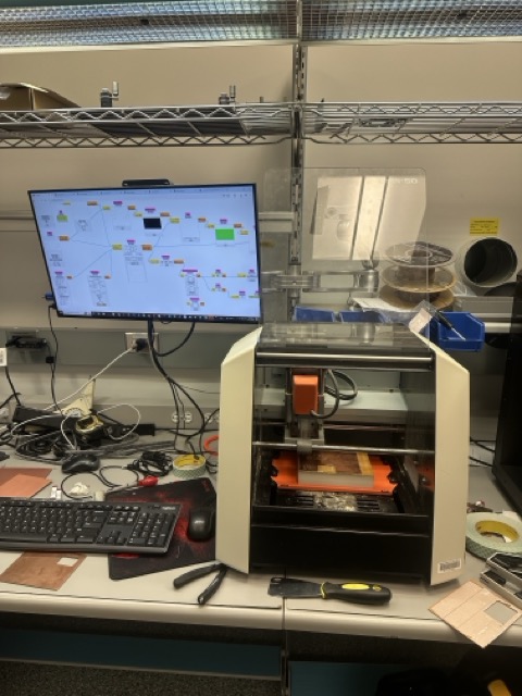
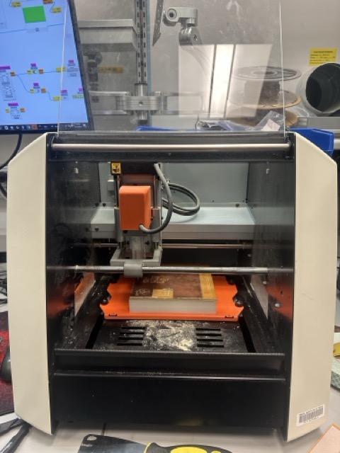
I exported the board outlines from Illustrator and then brought them into Fusion, where I made sure all components fit precisely within the board geometry. Once finalized, I milled the boards and moved into assembly.
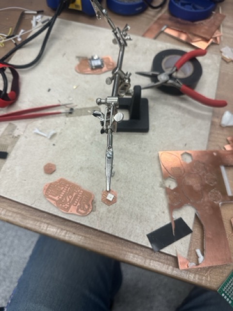
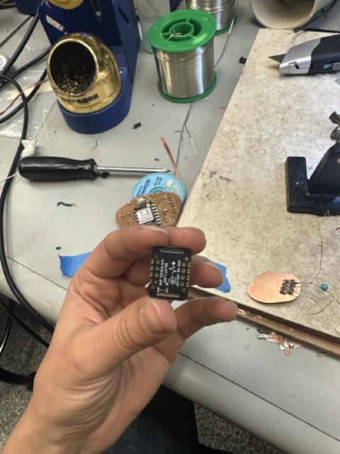
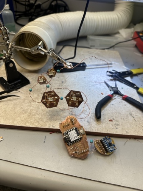
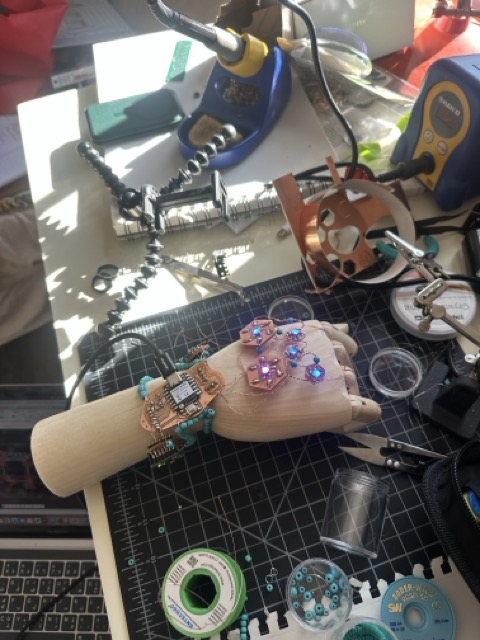
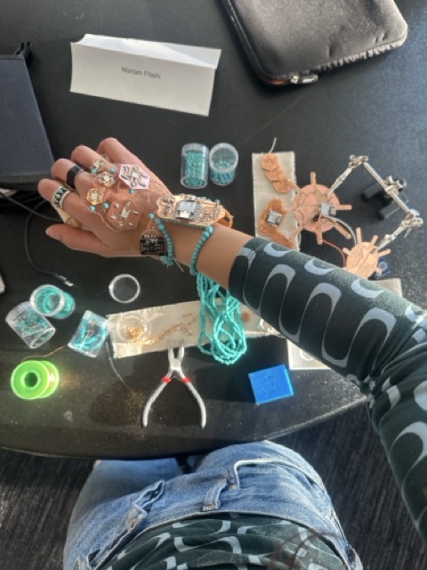
Assembly + Soldering
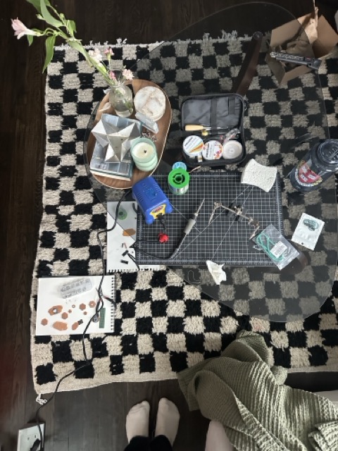
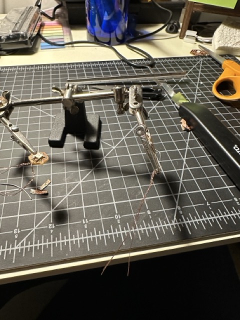
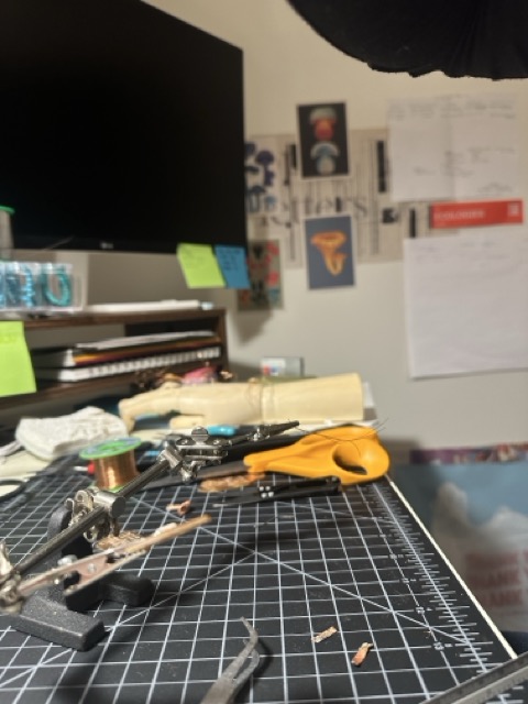
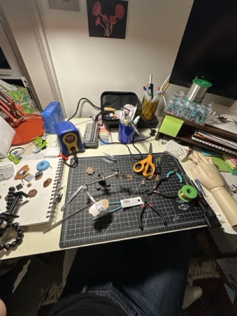
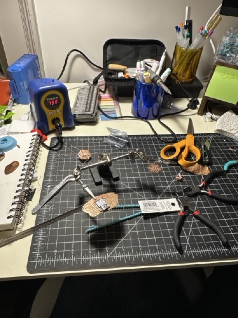
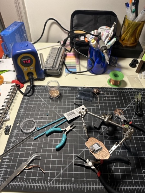
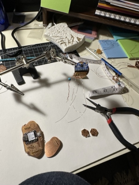
The soldering phase was by far the most labor-intensive part of the project.
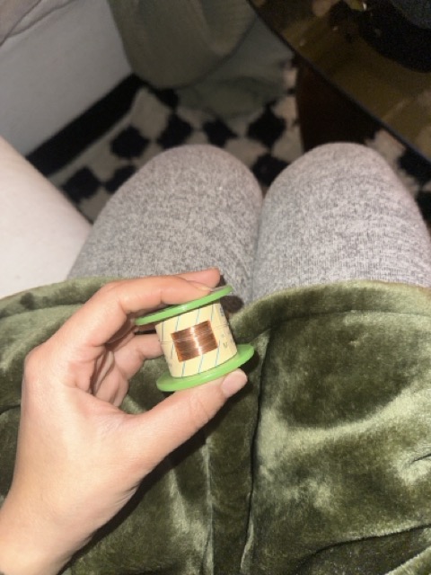
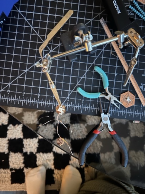
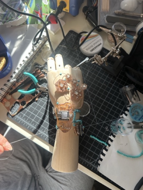
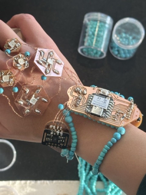
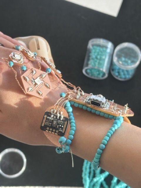
I used magnet wire, which meant that every single connection required manually scraping the enamel coating off the wire ends before soldering. This made the process extremely slow and precise. At this stage, I became very aware of how much patience and repetition traditional crafts demand—every connection mattered.
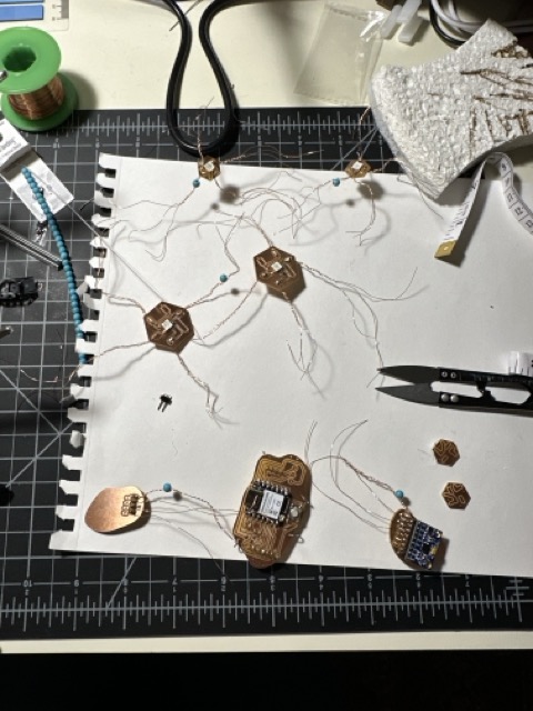
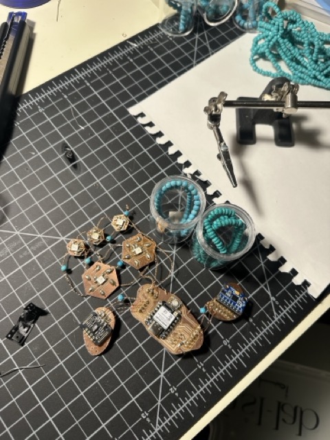
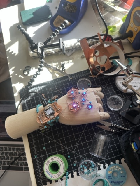
I braided the magnet wire intentionally:
- to increase conductivity
- to prevent failure if a single thin wire broke during wear
- to improve the structural integrity of the piece
- and because copper allowed the wiring to visually disappear instead of making the piece look bulky or unattractive

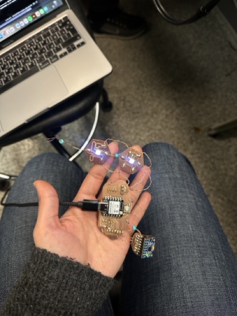
At some point during testing, I started feeling a slight sting when handling exposed copper—not an electric shock, but enough to make me confident that current was actually moving through the system. That moment gave me a bit of reassurance that the circuit was alive.
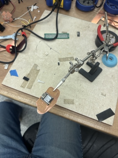
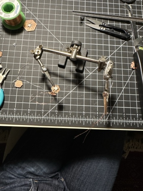
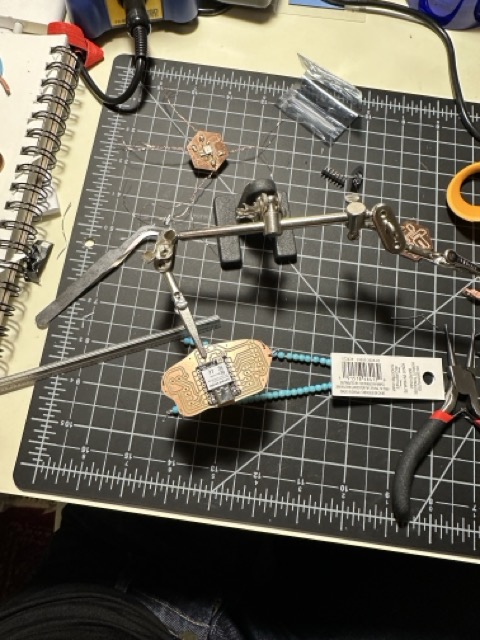
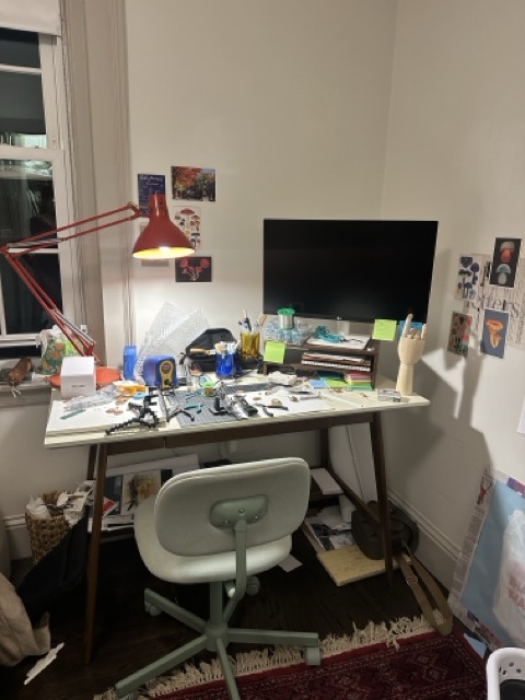
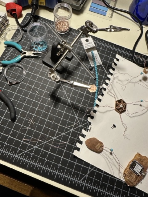
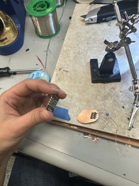
Debugging + Overnight Build
After lining everything up, I went back to the lab around 9 p.m. and stayed until 6 a.m., soldering, troubleshooting, fixing joints, and redoing connections.
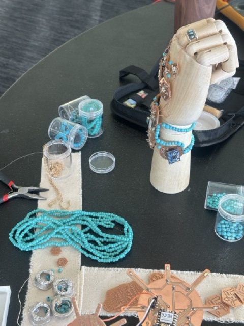
Beading:
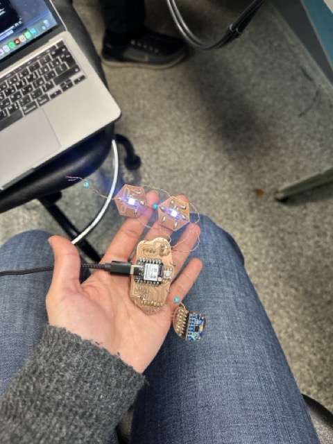
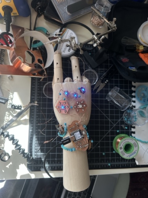
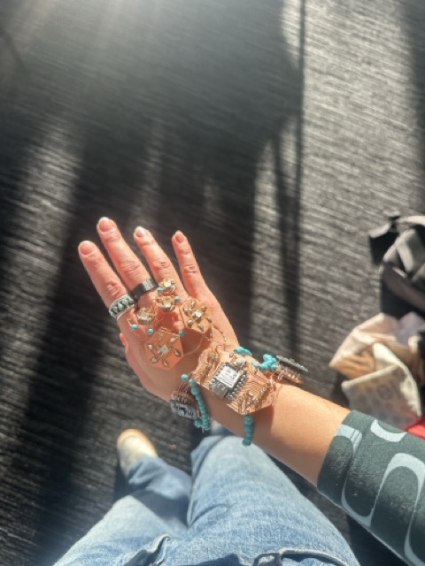
I left that morning with three NeoPixels not working. The next day, after flipping components and reworking connections, I managed to get all five LEDs functioning.
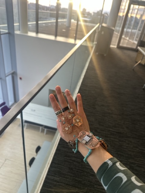
The system worked.
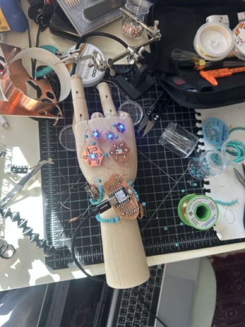
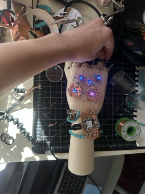
Unfortunately, I only documented this moment with a photograph and not a video.
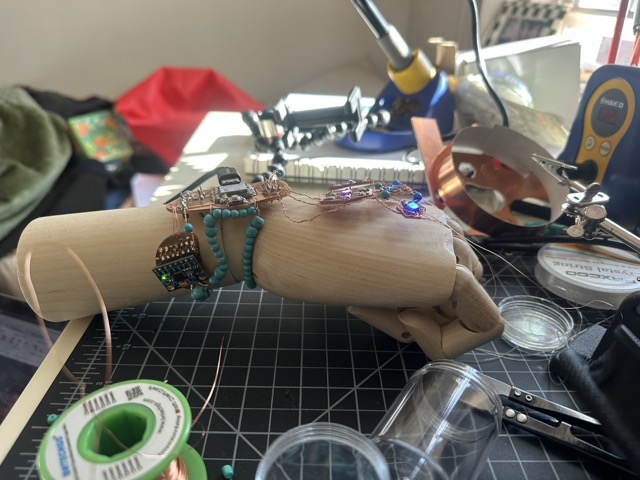
Final Review + Failure Mode
By the time I arrived at the final review, some of the very sensitive magnet wire connections had shorted against each other, likely due to movement and handling. I sat in the corner with a soldering iron trying to fix it in time, but I wasn't able to restore full functionality before presenting to Neil.
Although the piece did work, I was unable to demonstrate it live or show video documentation of it operating.
Reflection
This project taught me a lot about:
- designing electronics at a jewelry scale
- the limits of magnet wire for wearables
- the fragility of exposed connections
- and the importance of strain relief, insulation, and encapsulation in future iterations
What I successfully demonstrated was:
- custom PCB design
- schematic creation
- milling and assembly
- LED control
- system-level thinking at a very small scale
What I would improve next:
- better insulation between conductors
- more robust connectors
- a housing or coating to protect connections
- and improved documentation during moments of success
Code + Documentation
The code used for this project is included below. All images of the process, boards, soldering, and final assembly are included in this documentation.
Initial NeoPixel Test Code
#include <Adafruit_NeoPixel.h>

#define NEOPIXEL_PIN  3     // GPIO number (NOT D3)
#define NUM_PIXELS    5

Adafruit_NeoPixel pixels(NUM_PIXELS, NEOPIXEL_PIN, NEO_GRB + NEO_KHZ800);

void setup() {
  pixels.begin();        // initialize NeoPixel
  pixels.clear();        // clear all pixels
  pixels.setBrightness(80);

  // turn ALL pixels ON (white)
  for (int i = 0; i < NUM_PIXELS; i++) {
    pixels.setPixelColor(i, pixels.Color(50, 50, 50));
  }
  pixels.show();
}

void loop() {
  // do nothing
}
Motion-Triggered Breathing LED Code
#include <Wire.h>
#include <Adafruit_MPU6050.h>
#include <Adafruit_Sensor.h>
#include <Adafruit_NeoPixel.h>

// ---------- EDIT THESE ----------
#define I2C_SDA       8       // your SDA pin
#define I2C_SCL       9       // your SCL pin

#define NEOPIXEL_PIN  3       // use a GPIO number (NOT D3)
#define NUM_PIXELS    5
#define BASE_BRIGHTNESS  80   // max brightness during breathing (0-255)
// ------------------------------

// Motion detection tuning
float baselineG = 1.0f;
float AGITATED_DELTA_G = 0.30f;     // higher = needs stronger movement to count
uint32_t HIT_DEBOUNCE_MS = 250;     // prevent one shake from counting many times

// "5 times in a minute"
const int TRIGGER_HITS = 5;
const uint32_t WINDOW_MS = 60000;   // 1 minute

Adafruit_MPU6050 mpu;
Adafruit_NeoPixel pixels(NUM_PIXELS, NEOPIXEL_PIN, NEO_GRB + NEO_KHZ800);

// We store hit timestamps to implement a rolling 60s window
uint32_t hitTimes[32];  // enough room for plenty of hits
int hitCount = 0;

uint32_t lastHitMs = 0;

float mag3(float x, float y, float z) {
  return sqrtf(x*x + y*y + z*z);
}

void setAll(uint8_t r, uint8_t g, uint8_t b) {
  for (int i = 0; i < NUM_PIXELS; i++) {
    pixels.setPixelColor(i, pixels.Color(r, g, b));
  }
  pixels.show();
}

void calibrateBaseline() {
  const int samples = 200;
  float sum = 0;
  for (int i = 0; i < samples; i++) {
    sensors_event_t a, g, t;
    mpu.getEvent(&a, &g, &t);
    float accelMagG = mag3(a.acceleration.x, a.acceleration.y, a.acceleration.z) / 9.80665f;
    sum += accelMagG;
    delay(5);
  }
  baselineG = sum / samples;
}

// Remove hits older than 60 seconds
void pruneOldHits(uint32_t now) {
  int writeIdx = 0;
  for (int i = 0; i < hitCount; i++) {
    if (now - hitTimes[i] <= WINDOW_MS) {
      hitTimes[writeIdx++] = hitTimes[i];
    }
  }
  hitCount = writeIdx;
}

void addHit(uint32_t now) {
  if (hitCount < (int)(sizeof(hitTimes) / sizeof(hitTimes[0]))) {
    hitTimes[hitCount++] = now;
  } else {
    // If array full, drop oldest by shifting left (rare)
    for (int i = 1; i < hitCount; i++) hitTimes[i - 1] = hitTimes[i];
    hitTimes[hitCount - 1] = now;
  }
}

// Smooth breathing brightness: 0..BASE_BRIGHTNESS..0
// Uses a sine wave for soft transitions.
uint8_t breathingBrightness(uint32_t now) {
  // period of one full inhale+exhale (ms)
  const float periodMs = 7000.0f; // slower breathing, tweak if you want
  float phase = fmodf((float)now, periodMs) / periodMs; // 0..1

  // sine wave mapped to 0..1
  float s = 0.5f - 0.5f * cosf(2.0f * PI * phase);

  return (uint8_t)(s * BASE_BRIGHTNESS);
}

void setup() {
  Serial.begin(115200);
  delay(200);

  pixels.begin();
  pixels.clear();
  pixels.show();

  Wire.begin(I2C_SDA, I2C_SCL);
  Wire.setClock(400000);

  if (!mpu.begin()) {
    // blink red if MPU not found
    while (true) {
      setAll(60, 0, 0); delay(200);
      setAll(0, 0, 0);  delay(200);
    }
  }

  mpu.setAccelerometerRange(MPU6050_RANGE_8_G);
  mpu.setGyroRange(MPU6050_RANGE_500_DEG);
  mpu.setFilterBandwidth(MPU6050_BAND_21_HZ);

  // ready indicator
  setAll(0, 0, 20);
  calibrateBaseline();
  setAll(0, 0, 0);
}

void loop() {
  uint32_t now = millis();

  // Read accel
  sensors_event_t a, g, t;
  mpu.getEvent(&a, &g, &t);

  float accelMagG = mag3(a.acceleration.x, a.acceleration.y, a.acceleration.z) / 9.80665f;
  float delta = fabsf(accelMagG - baselineG);

  // Rolling minute window maintenance
  pruneOldHits(now);

  // Detect an "agitated" movement event
  if (delta > AGITATED_DELTA_G && (now - lastHitMs) > HIT_DEBOUNCE_MS) {
    lastHitMs = now;
    addHit(now);

    // optional tiny feedback flash
    // setAll(20, 0, 20); delay(20); setAll(0,0,0);
  }

  bool breathingMode = (hitCount >= TRIGGER_HITS);

  if (breathingMode) {
    // Breathing: dim in/out smoothly
    uint8_t b = breathingBrightness(now);
    pixels.setBrightness(b);

    // Choose a calming color (teal). Change if you want.
    for (int i = 0; i < NUM_PIXELS; i++) {
      pixels.setPixelColor(i, pixels.Color(0, 40, 80));
    }
    pixels.show();

  } else {
    // Calm state: lights off (or very faint)
    pixels.setBrightness(255);
    setAll(0, 0, 0);
  }

  delay(20);
}
What does it do?
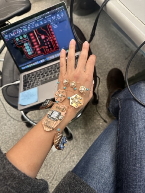
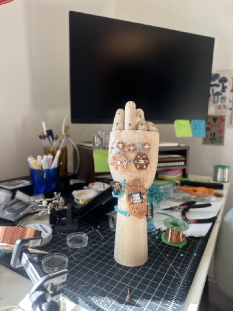
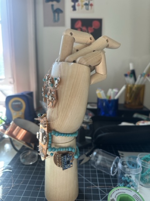
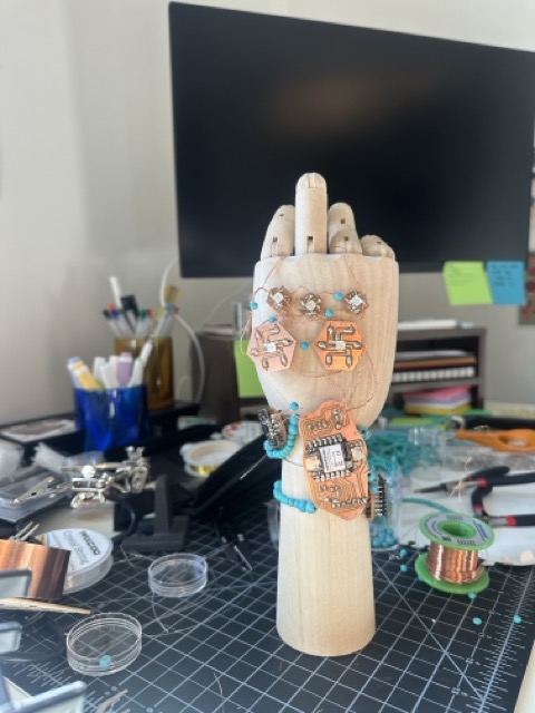
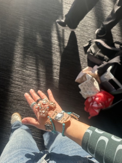
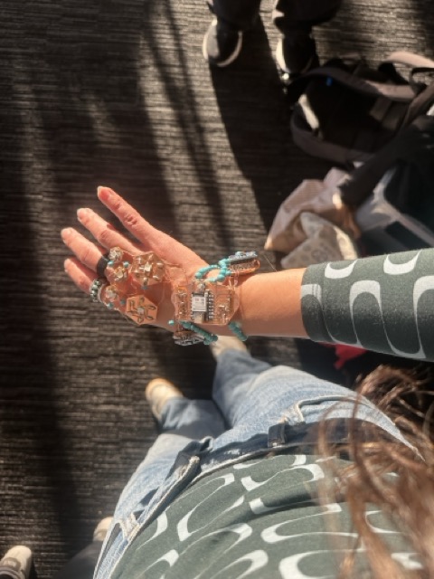
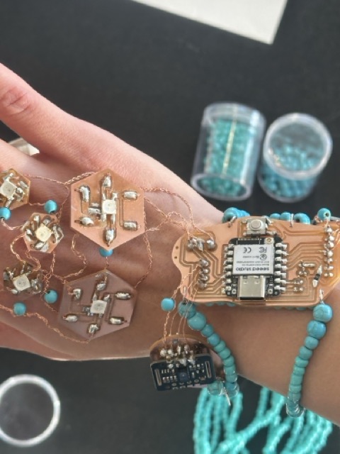
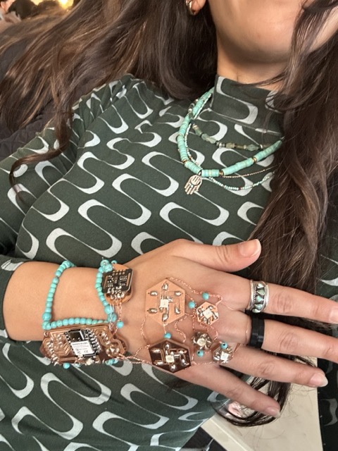
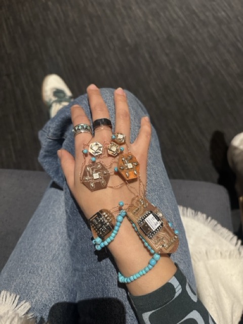
This project is a wearable electronic jewelry piece composed of custom PCB-based LED beads connected through braided conductive wiring. The system integrates light, motion, and biometric sensing, allowing the jewelry to function as an active, responsive object rather than a static ornament.
The LEDs are controlled by a microcontroller, while body movement is sensed through an MPU6050 accelerometer and gyroscope, and biometric data is explored through a MAX30102 pulse reader. A button allows for direct user interaction, such as switching modes or resetting behavior.
The project explores the limits of electronics at jewelry scale, where fragility, surface area, and craft labor become dominant design constraints.
Who's done what beforehand?
This work builds on existing precedents in:
- wearable computing and electronic jewelry
- NeoPixel-based LED wearables
- soft circuits and e-textiles
- cyber-jewelry where electronics are made visible
Most existing examples rely on flexible PCBs, fabric substrates, or larger wearable formats. This project differs by focusing on:
- rigid PCB beads
- extremely small surface areas
- traditional jewelry logic (beads, braiding, modular assembly)
What sources did you use?
Technical sources
- HTMAA lectures and class documentation
- Adafruit NeoPixel documentation
- ESP32 documentation
- MPU6050 and MAX30102 datasheets
- Fab Academy PCB milling workflows
Design sources
- traditional jewelry construction methods
- craft practices involving repetitive hand labor
- Blob Creator for organic form generation
- Adobe Illustrator and Fusion 360 for layout and fabrication
What did you design?
I designed:
- the overall wearable system
- custom PCB bead geometries (hexagonal and organic blob forms)
- the electronic schematic and board layout
- the wiring and braiding strategy
- the physical assembly logic as a wearable object
What materials and components were used?
Electronics Components
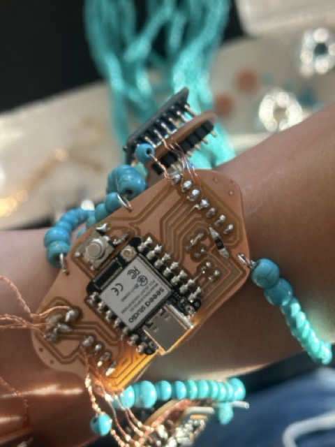
- ESP32 microcontroller
- NeoPixel LEDs (WS2812-type, 5x)
- MPU6050 accelerometer + gyroscope
- MAX30102 pulse reader
- Momentary button
- Custom milled PCBs
- Magnet wire (enameled copper)
- Copper wire
- Solder (no flux used)
- USB cable
Materials
- FR-1 copper-clad board
- Copper wiring
- Solder
- Minimal insulation (identified as a limitation)
Where did they come from?
- Electronics components (ESP32, NeoPixels, MPU6050, MAX30102, button): Ordered on Amazon, coordinated through Anthony, and supplemented with MIT shop inventory.
- PCB material, wire, solder: Sourced from the MIT shop.
- Fabrication tools and machines: MIT Media Lab and shop facilities.
How Much did they cost? (approximate)
| Item | Approx. Cost (USD) |
|---|---|
| ESP32 microcontroller | $8 – $12 |
| NeoPixels (5x) | $5 – $8 |
| MPU6050 | $3 – $6 |
| MAX30102 | $8 – $15 |
| Button | ~$1 |
| FR-1 copper board | ~$5 |
| Magnet wire | ~$6 |
| Copper wire + misc. | ~$3 |
| Solder | ~$3 |
| Estimated total | $40 – $55 |
What parts and systems were made?
- Custom PCB LED beads
- Integrated sensor system (motion + pulse)
- Electrical power and data distribution system
- Braided conductive wiring system
- Fully assembled wearable prototype
What tools and processes were used?
Design
- Hand sketching
- Blob Creator
- Adobe Illustrator
- Fusion 360 (schematic, PCB layout, CAM)
Fabrication
- PCB milling
- Extensive manual soldering
- Magnet wire scraping and preparation
- Wire braiding and jewelry-style assembly
Programming
- Arduino environment
- NeoPixel control code
- Sensor integration (MPU6050 and MAX30102)
What questions were answered?
- Can PCBs function as jewelry beads?
- How small can wearable electronics become before fragility dominates?
- Can motion and biometric sensors function at jewelry scale?
- How does craft labor scale in electronic fabrication?
- What happens when electronics are treated as ornament rather than hidden infrastructure?
What worked? What didn't?
What worked
- PCB design and milling
- LED control and system logic
- Braided wiring for redundancy and strength
- Conceptual framing of electronics as jewelry
What didn't
- Magnet wire insulation reliability
- Strain relief between beads
- Long-term durability
- Stability of extremely sensitive connections
- Full documentation of the working state
How was it evaluated?
- Functional LED testing
- Sensor testing during assembly
- Physical wear and handling tests
- Visual and spatial evaluation as jewelry
- Final review feedback
The system did function, but shorting occurred by the time of final presentation, preventing live demonstration.
What are the implications?
This project reveals:
- the limits of miniaturization in wearable electronics
- the necessity of insulation, encapsulation, and strain relief
- the overlap between electronics, craft, and labor
- how failure exposes critical design constraints
Future iterations would involve:
- encapsulated wiring
- improved connectors
- flexible PCBs or hybrid rigid-flex systems
- intentional documentation of functional moments
Sun Pendant PCB — Week 04-05 (October 2024)
What I tried
- Designed circular PCB with capacitive touch center and six LED rays in Fusion 360 Electronics
- Milled prototype on FR-1 using Roland SRM-20
- Soldered Seeed XIAO RP2040, LEDs, and resistors
- Programmed capacitive touch sensing and LED animations
Process notes
- Used Fusion 360 Electronics for schematic and board layout
- Material: FR-1 for prototype, planning ENIG finish for final version
- Components: XIAO RP2040, 6x warm-white LEDs, 470Ω resistors, 1MΩ for touch bias
- Programming: Arduino IDE with capacitive touch library
Results / Evidence
- Successfully milled and assembled first prototype
- Capacitive touch works reliably at jewelry scale
- LED animations create desired "breathing" and "chasing" effects
- Form factor works well as pendant—comfortable to wear
- Some challenges with LED brightness consistency (resolved with resistor adjustments)
Decisions
- Keeping the circular sun motif—it works both functionally and aesthetically
- Moving forward with ENIG gold finish for final version (jewelry-quality appearance)
- Refining LED placement and brightness for better visual effect
- Exploring battery power options for future iterations (earring designs)
Next steps
- Order final boards with ENIG finish from board house
- Refine firmware for more sophisticated light patterns
- Explore additional sensor integration (temperature, motion)
- Design mounting system (jump rings, chain, earring hooks)
Project Overview
I'm developing a wearable electronics line called HardWear, an extension of my broader asl practice that explores craft, material memory, and sustainability. This project brings those values into technology and jewelry, creating pieces that are both functional and meaningful.
Each piece is both aesthetic and functional, carrying sensors or circuits that respond to the body and environment. I want to merge my background in art and materiality with the technical skills learned throughout HTMAA — translating code, copper, and conductivity into intimate, tactile forms.
💡 Concept
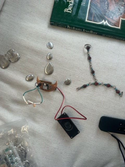
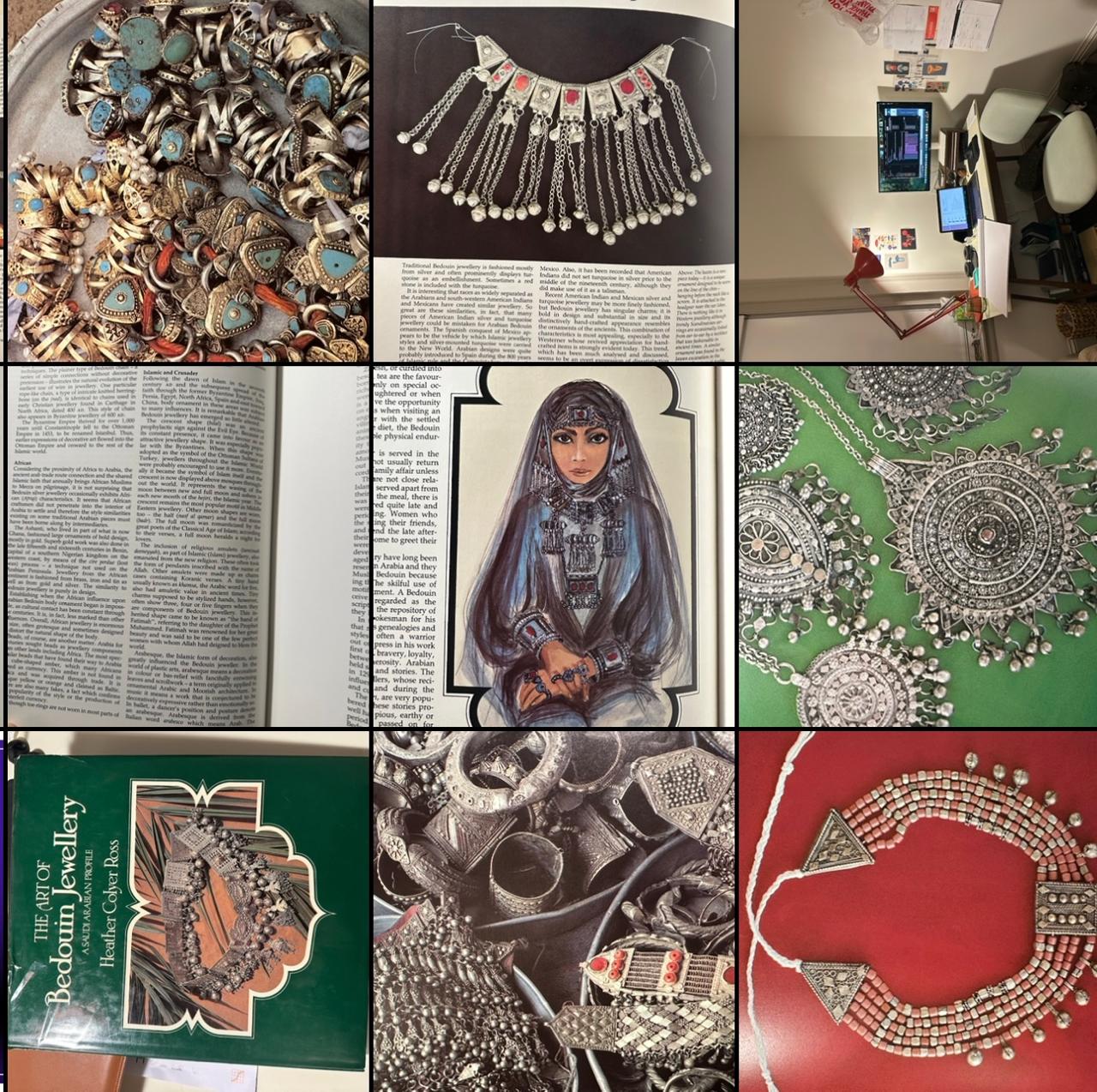
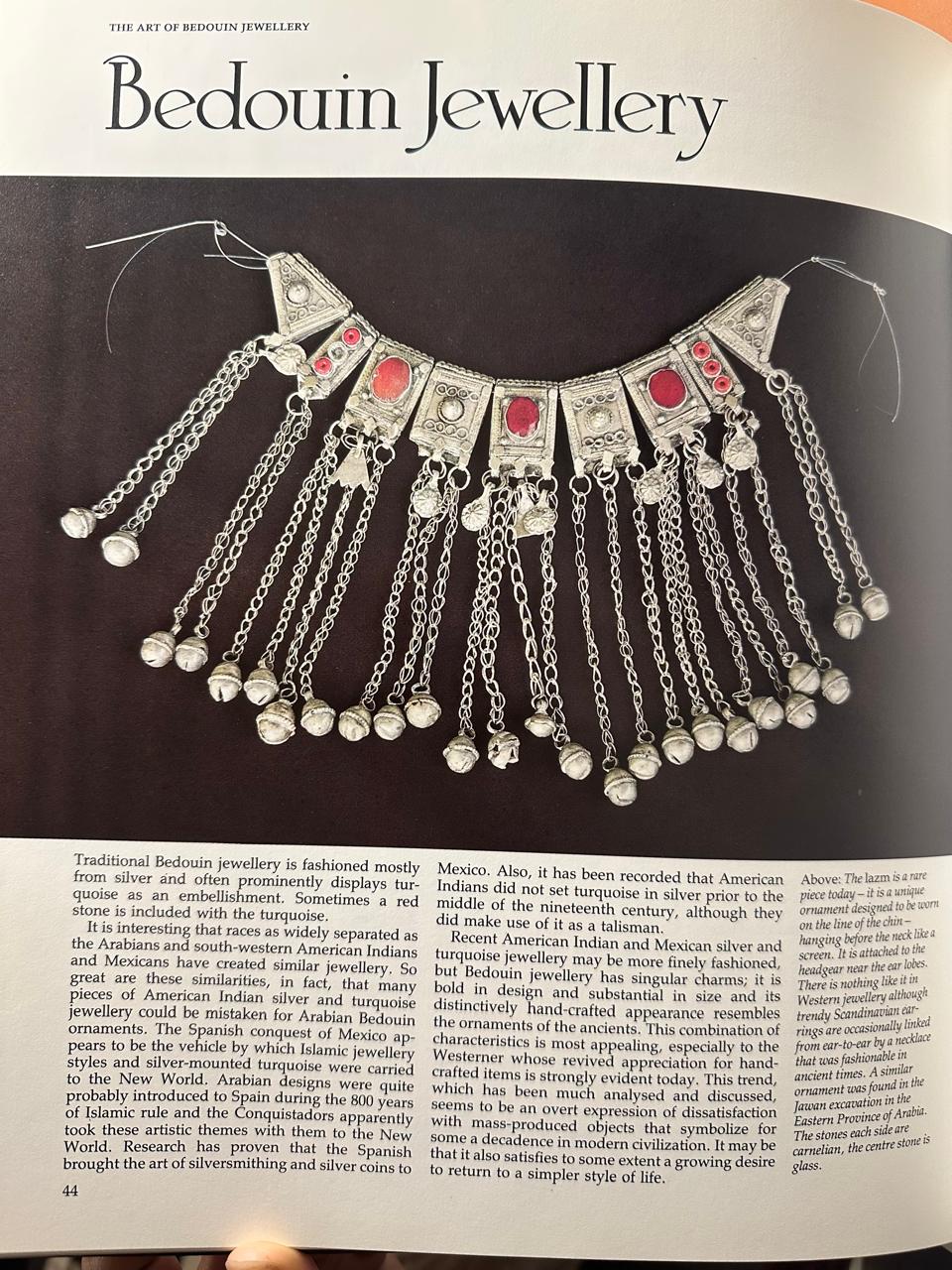
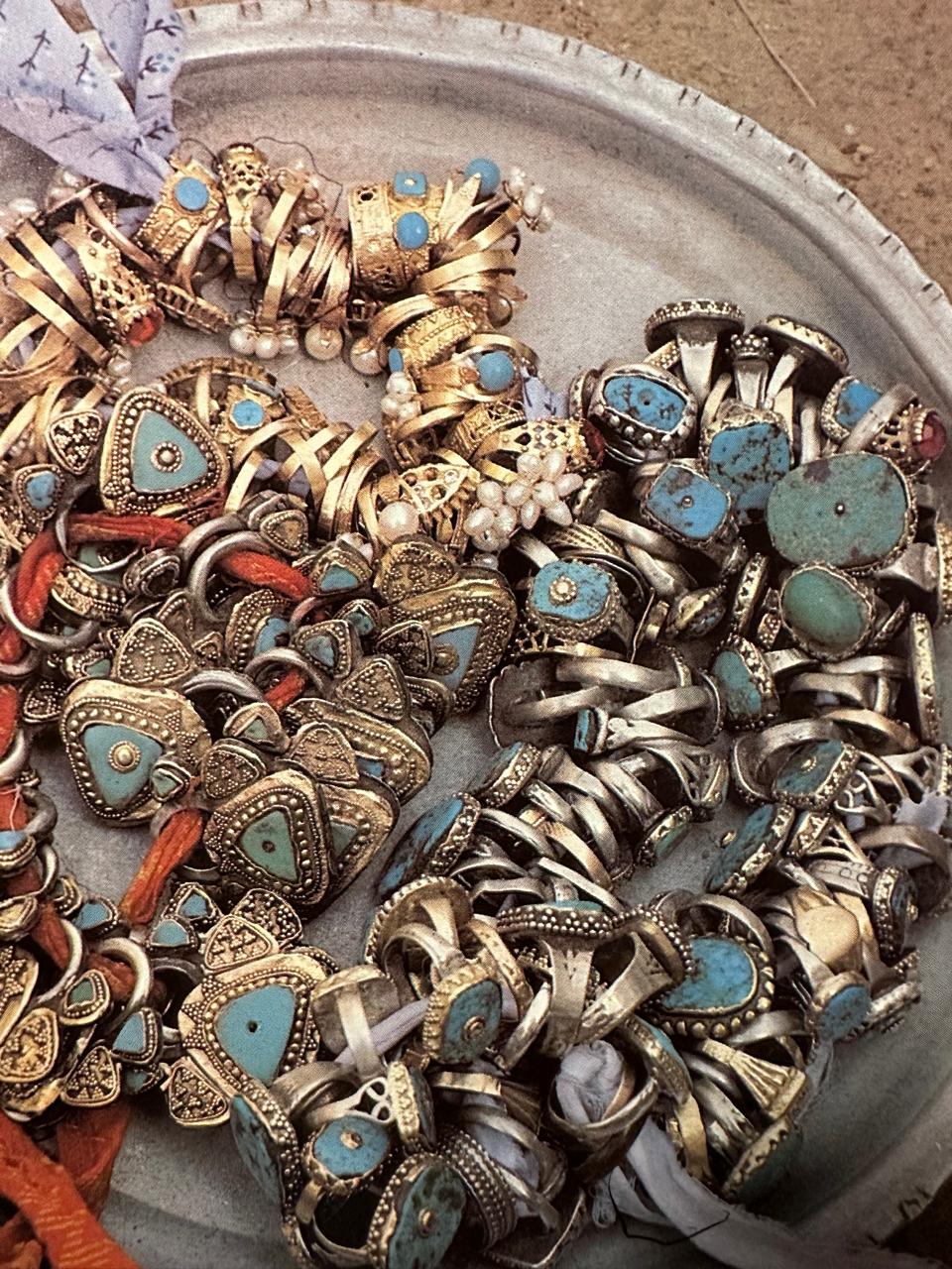
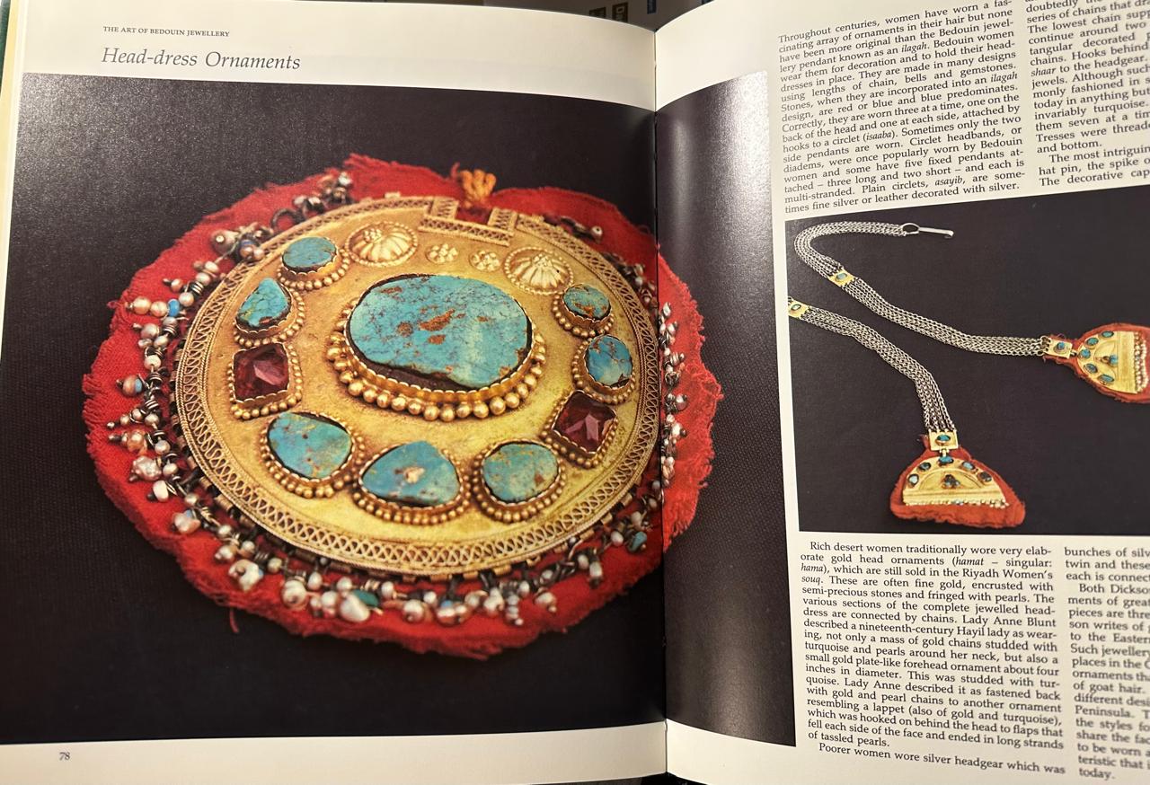
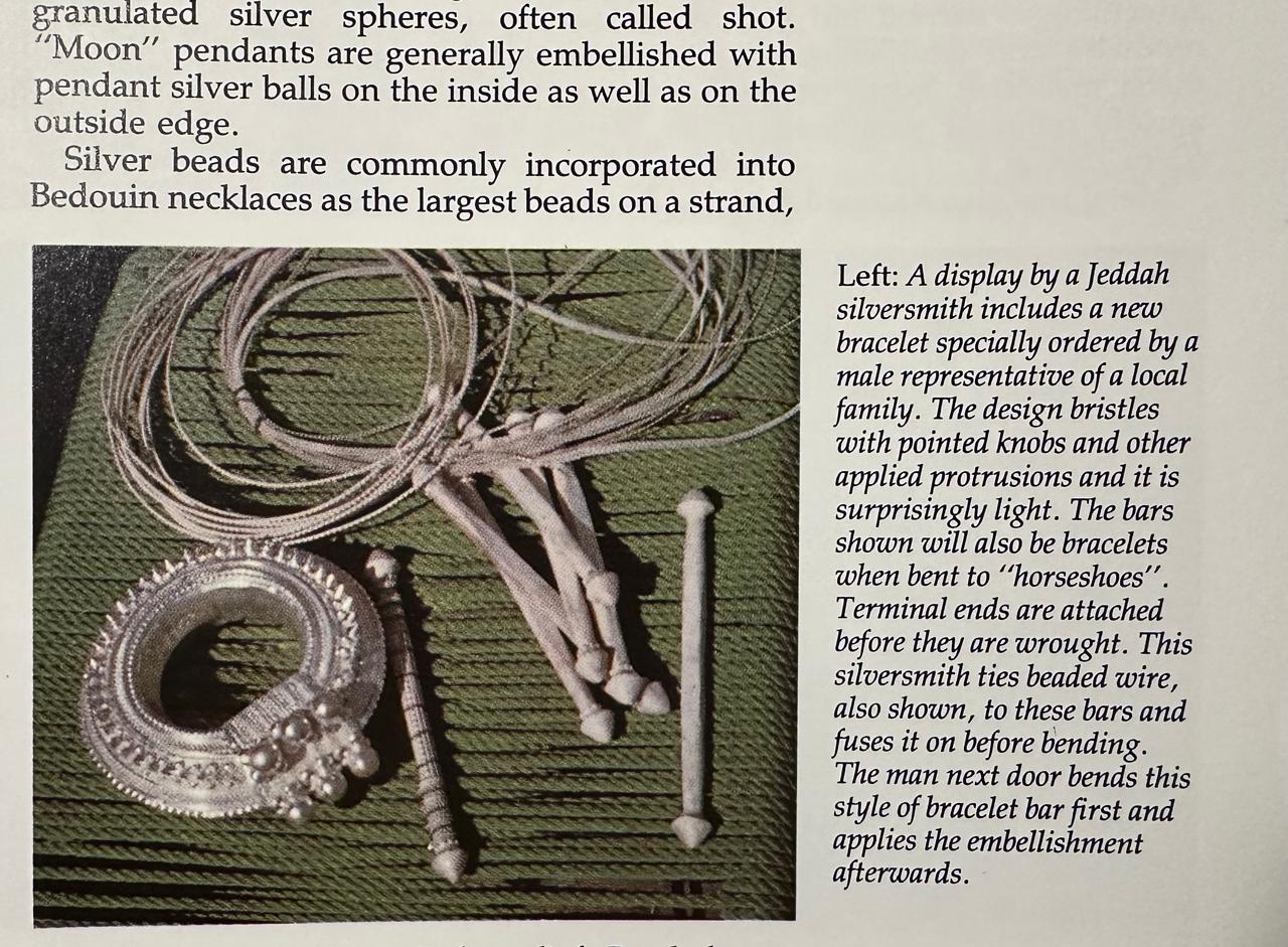
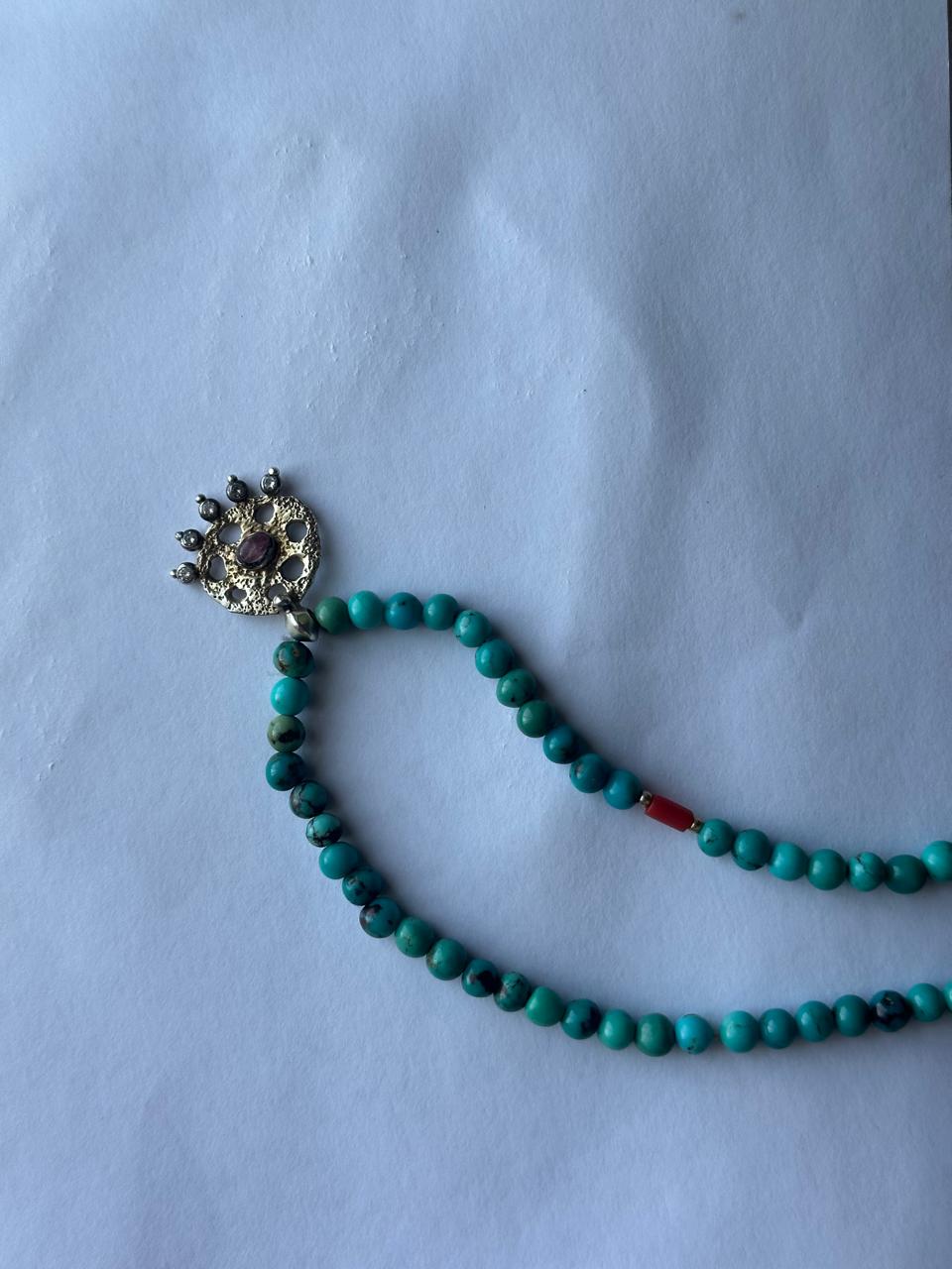
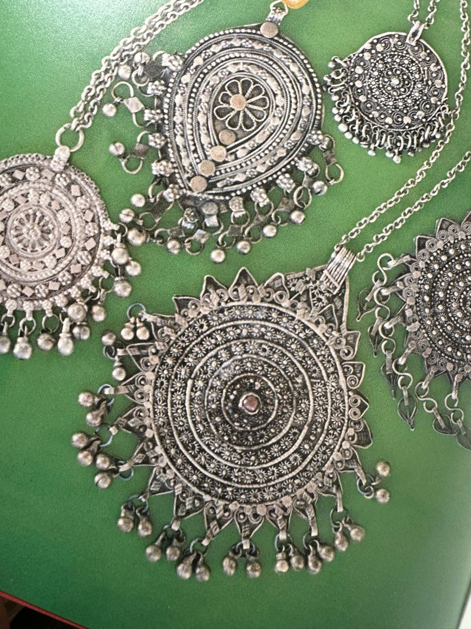
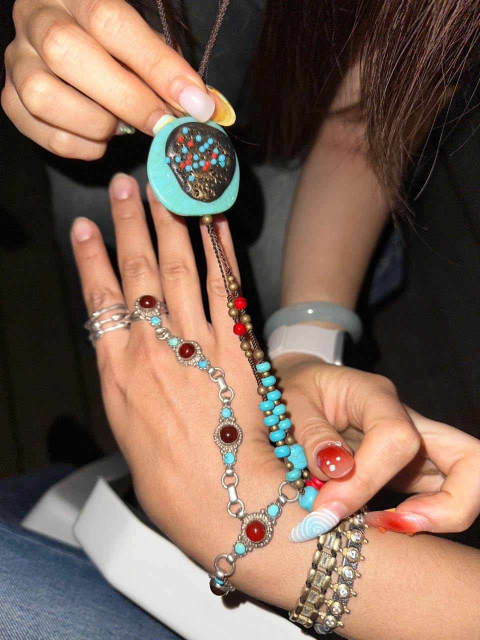
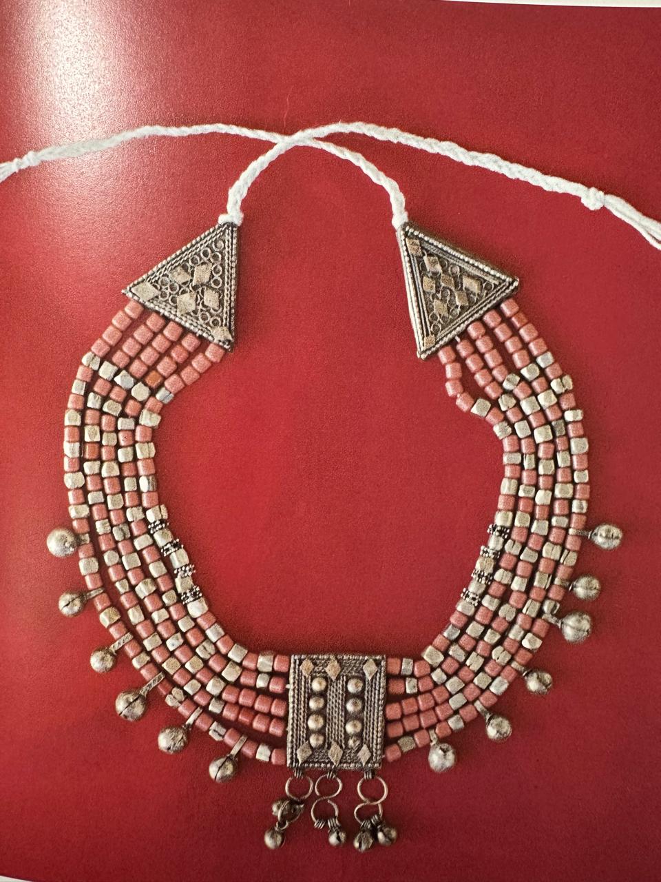
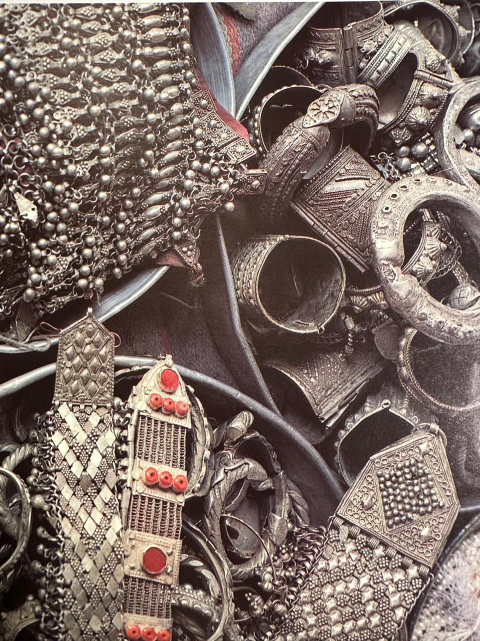
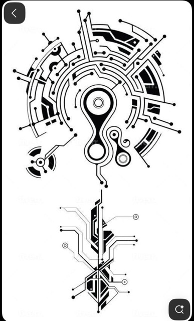
HardWear is cyber-organic jewelry — pieces that sense, react, or record traces from the body and environment. The project merges traditional Bedouin jewelry forms with modern electronics, creating a dialogue between craft and computation, heritage and circuitry.
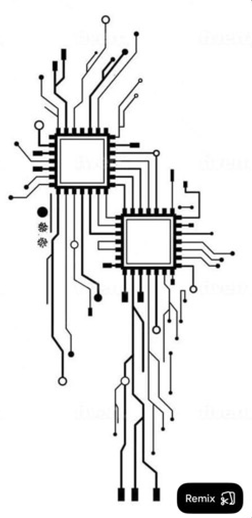
HardWear investigates the animacy of materials — circuits that behave like veins, traces that echo scars or root systems, and jewelry that listens, senses, and remembers.
Each piece acts as a "cyber-amulet" — an object that connects the digital to the organic:
- It senses something from the body or surroundings
- It reacts through light, motion, or stored data
- It becomes a symbolic "living artifact," continuing my family's lineage of goldsmithing in Al-Balad while reimagining craft through electronics
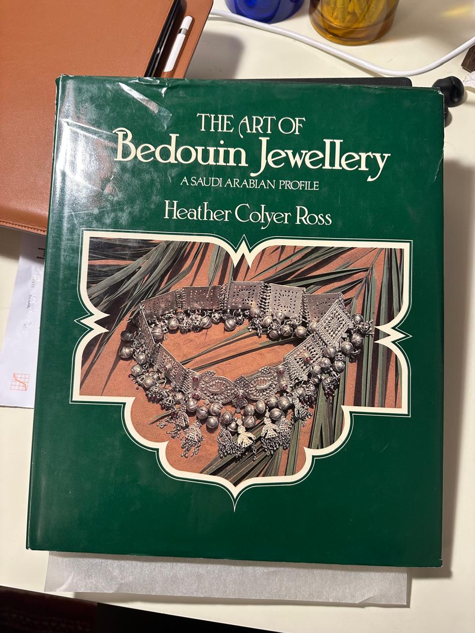
Bedouin Jewellery Inspiration
Traditional Bedouin silverwork, turquoise settings, and organic forms that inform the HardWear aesthetic.


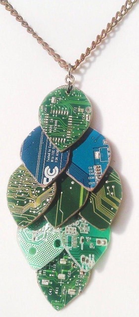
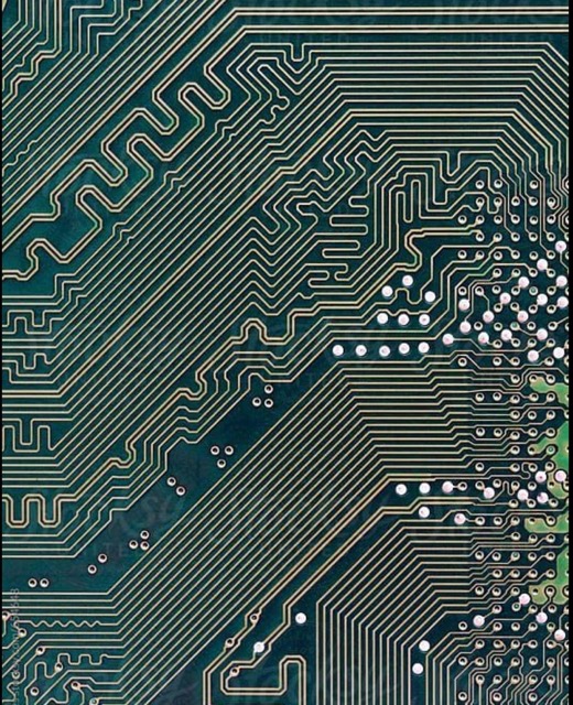
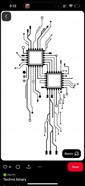
Cyber-Organic Inspiration
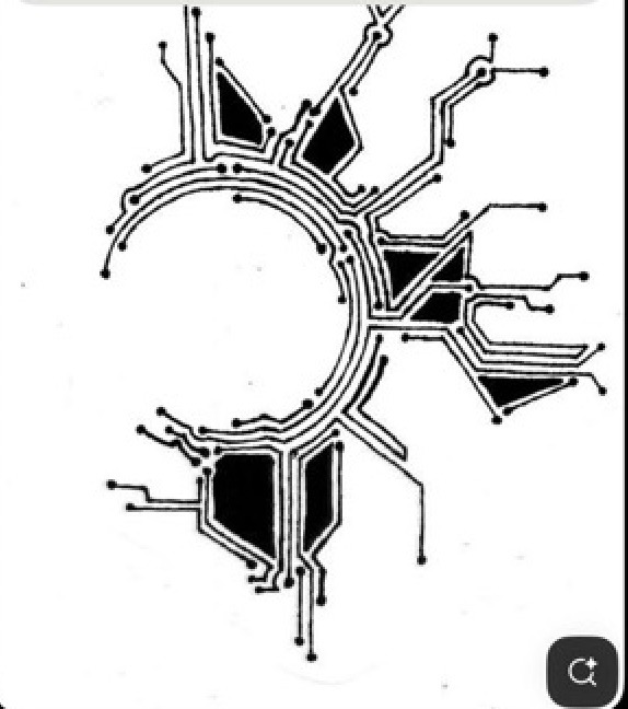
Prototype – Sun Pendant PCB
The first prototype is a circular board with six LED rays that glow when you touch the copper center. It functions as a cyber-amulet — part ornament, part responsive circuit.
Components
- Seeed XIAO RP2040 microcontroller
- Capacitive touch sensing at the center
- Six warm-white LEDs on PWM pins for smooth light animations
- Designed in Fusion Electronics
- First prototype milled on FR-1, final version ordered ENIG gold finish for jewelry feel
What It Will Do
The final artifact will be a wearable electronic jewelry piece that:
- Reacts to the body through capacitive touch or environmental sensing
- Outputs light animations through embedded LEDs (symbolizing energy, warmth, and connection)
- Optionally logs or remembers sensor data (memory as metaphor)
- Visually merges organic motifs (veins, rays, tree rings) with electronic traces
This prototype will demonstrate:
- Circuit design and PCB fabrication for wearable scales
- Sensor integration (touch, light, or temperature)
- Embedded programming (interaction + simple logic)
- Aesthetic integration of electronics and jewelry craft
Precedents
There are precedents in wearable electronics, but few merge traditional craft lineage with modern fabrication:
- Nadya Peek & Neil Gershenfeld's Fab Academy projects — PCB jewelry prototypes
- Vadim Gordeev — mechanical jewellery
HardWear extends this dialogue into a Middle Eastern craft context, fusing Bedouin metal forms with cybernetic circuitry.
Inspiration – Nadya Peek
Nadya Peek views fabrication as a cultural and expressive act. Her work on Making Machines that Make demonstrates how machines and circuits can be design objects themselves, not just tools for production.
Her approach to low-volume, personal fabrication resonates deeply with my practice. She has influenced my view of PCBs as artifacts — not just function but material poetry. Every PCB in HardWear is both circuit and ornament, showing that technology and tradition can coexist.
⚙️ What I Will Design
- Custom PCB jewelry boards inspired by Bedouin amulets and anatomical systems
- Functional electronics:
- Capacitive touch sensing
- Light output (LEDs)
- Optional data logging (temperature, motion, or environmental)
- Form language: Curves and geometries derived from organic systems (veins, roots, solar flares)
- Wearability system: Mounting holes, soldered jump rings, optional conductive chains
⚙️ Process
The process involves refining both electronics and craftsmanship, balancing clean routing patterns with aesthetic copper design. Each week builds toward a full HardWear collection — pieces that "feel alive" through sensors, light, or memory.
1. Design & Modeling
- Sketch + Illustrator concept art (organic / Bedouin / anatomical motifs)
- Convert to SVG → import into Fusion Electronics as board outlines
- Component layout, routing, copper pours, and aesthetic patterning
2. Fabrication
- Prototype on FR-1 using the Roland SRM-20 for single-layer milling
- Final version: order from board house (ENIG finish, 0.8 mm FR-4, matte black or white mask)
- Solder SMD components (LEDs, resistors, Seeed XIAO RP2040)
3. Programming
- Firmware on XIAO RP2040 (Arduino):
- Capacitive touch pad → toggles light animations
- LED "breathing" and "chasing" patterns
- Optional sensor integration (light sensor or accelerometer)
4. Finishing
- Sand and clean board edges for comfort
- Add conformal coating or resin to seal
- Attach jump rings / earring hooks / chain
5. Documentation
- Process photos, code snippets, BOM, design files, and final renders/video
Materials & Components
| Component | Purpose | Notes |
|---|---|---|
| Seeed XIAO RP2040 | Microcontroller | Small, USB-C powered, 3.3V logic |
| LEDs (0603, warm white) ×6–8 | Light output | Each ray of the jewelry |
| Resistors 470Ω ×6–8 | Current limiting for LEDs | Soft glow |
| 1MΩ resistor | Capacitive touch bias | Stabilizes sensor |
| FR-1 or FR-4 board | PCB substrate | ENIG finish for gold tone |
| Lead-free solder + flux | Assembly | Safe for skin contact |
| Jewelry findings (jump rings, hooks, chains) | Wearability | Metallic, aesthetic integration |
| Optional: NTC thermistor / microphone | Sensing expansion | For future iterations |
Processes
- EDA schematic design (Fusion 360 Electronics)
- PCB layout and fabrication (milling + outsourcing)
- Surface-mount soldering (fine SMD)
- Embedded programming (Arduino / C++)
- Mechanical finishing and jewelry assembly
- Documentation and photography
Timeline
| Week | Task |
|---|---|
| Week 05 | Finalize schematic and board layout (Sun v0.2) |
| Week 06 | Mill first prototype, test capacitive touch and LED brightness |
| Week 07 | Debug, adjust resistor values, refine copper patterns |
| Week 08 | Order final boards (ENIG finish) |
| Week 09 | Assemble final jewelry piece, test firmware |
| Week 10 | Photograph and document final result |
Questions to Answer
- How sensitive can capacitive touch be at jewelry scale?
- Can I combine multiple sensors (touch + temperature or motion) on one board?
- How can I make solder joints and traces look intentional — ornamental rather than purely functional?
- What's the most ergonomic way to wear or power it (USB vs battery)?
Evaluation Criteria
- Functional interactivity: Touch → light response
- Craft and finish quality: Clean soldering, wearability
- Integration of design and technology: Not just a working circuit, but a designed object
- Documentation quality: Clarity, process, reflection
- Novelty: Merging cultural craft and digital fabrication
Project Documentation
What does it do?
HardWear is a wearable electronic jewelry piece that responds to touch through capacitive sensing, activating LED light animations. The piece functions as a "cyber-amulet" that merges traditional Bedouin jewelry aesthetics with modern electronics, creating an object that is both ornamental and interactive.
Who's done what beforehand?
Precedents include Nadya Peek's PCB jewelry prototypes, Vadim Gordeev's mechanical jewelry, and various wearable electronics projects from the Fab Academy community. HardWear extends this work by specifically integrating Middle Eastern craft traditions (Bedouin silverwork) with cybernetic circuitry, creating a unique cultural-technical hybrid.
What sources did you use?
- Traditional Bedouin jewelry forms and motifs
- Fusion 360 Electronics for PCB design
- Seeed XIAO RP2040 documentation and Arduino libraries
- HTMAA course materials and community documentation
- Nadya Peek's work on fabrication as cultural expression
What did you design?
- Custom PCB: Circular board with six LED rays, capacitive touch center, and organic trace patterns
- Firmware: Arduino code for touch sensing and LED animation patterns
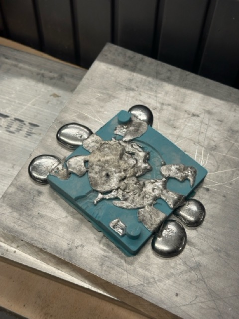
- Enclosure elements: Metal casting components for mounting and protection
- Wearability system: Jump rings, chain attachments, and mounting solutions
Materials and Components
| Component | Quantity | Cost (approx.) |
|---|---|---|
| Seeed XIAO RP2040 | 1 | $5 |
| Warm-white LEDs | 6 | $2 |
| Resistors (220Ω) | 6 | $0.50 |
| PCB fabrication (ENIG finish) | 1 | $25 |
| Metal casting materials | Various | $15 |
| Jump rings, chain, mounting hardware | Various | $5 |
| Total | ~$52.50 |
What parts and systems were made?
- PCB system: Custom-designed board with integrated touch sensing and LED control
- Firmware system: Embedded code for interaction and animation
- Enclosure system: Metal-cast mounting elements
- Wearability system: Attachment mechanisms for jewelry wear
What tools and processes were used?
- Design: Fusion 360 Electronics, Illustrator, hand sketching
- Fabrication: PCB milling (Roland SRM-20), professional PCB ordering, metal casting
- Assembly: Soldering (SMD and through-hole), multimeter testing, oscilloscope analysis
- Programming: Arduino IDE, serial monitoring, debugging tools
- Finishing: Sanding, cleaning, conformal coating, hardware attachment
What questions were answered?
- Can traditional jewelry aesthetics be successfully merged with modern electronics?
- How can capacitive touch sensing be implemented in a wearable form factor?
- What are the challenges of creating functional, beautiful PCB jewelry?
- How can metal casting techniques integrate with electronic components?
- What makes an electronic object feel "alive" or responsive?
What worked? What didn't?
What worked:
- PCB design successfully integrated aesthetic and functional elements
- Capacitive touch sensing provided intuitive interaction
- LED animations created the desired "living artifact" effect
- Fusion 360 Electronics workflow was effective for design iteration
What didn't work:
- Metal casting integration required more refinement than anticipated
- Power management needed circuit adjustments
- Initial enclosure design needed revision for better wearability
- Some capacitive touch sensitivity issues required firmware tuning
How was it evaluated?
The project was evaluated based on functional interactivity (touch → light response), craft and finish quality (clean soldering, wearability), integration of design and technology (not just a working circuit, but a designed object), documentation quality (clarity, process, reflection), and novelty (merging cultural craft and digital fabrication).
What are the implications?
HardWear demonstrates that technology and tradition can coexist, creating objects that honor cultural heritage while embracing digital fabrication. The project shows how electronics can be integrated into jewelry in ways that are both functional and meaningful, opening possibilities for future wearable electronics that connect craft, culture, and computation.
Reflections
Every PCB in HardWear is both circuit and ornament. The goal is to show that technology and tradition can coexist, creating forms that are personal, poetic, and functional.
A working, wearable, sun-inspired PCB pendant that lights up when touched — bridging ancestral jewelry craft, modern electronics, and design storytelling. This piece becomes the foundation for a larger collection exploring body, environment, and technology as one connected system: HardWear: cyber-organic jewelry.
Idea Progression and Inputs
LED Inspiration
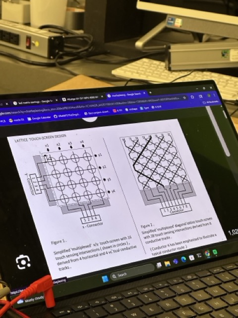
JD Conversation: Inspired idea of using multiple LEDs per pin through multiplexing and Charlie-plexing techniques. This allows controlling many LEDs with fewer pins, opening up possibilities for more complex lighting patterns.
Battery-powered earring designs: Exploring wearable electronics that are self-contained and don't require USB connection.
Technical Research & Materials
To Do & Research Areas
- Battery options: Exploring power sources for wearable electronics
- Charlie-plexing / Multiplexing: Techniques for controlling multiple LEDs with fewer pins
- Conductive materials: General conductivity material options for traces and connections
- Magnet wire idea: Enamelled copper wire — two running next to each other won't short out, allowing for flexible conductive paths in jewelry
Sensor Research
Exploring different sensor options for biophysical interaction:
- Infrared LED: Reads blood pumping (pulse/heart rate monitoring)
- Temperature sensors:
- LM35DZ
- LM335
- BMP180 (communicates over I2C) — from Random Nerd Tutorials
Key Concepts
- Multiplexing / Charlie-plexing: Control many LEDs with fewer GPIO pins
- Enamelled copper wire: Insulated conductors that can run parallel without shorting
- I2C communication: BMP180 temperature sensor uses this protocol
- Battery power: Self-contained wearable electronics without USB dependency