Week 07: Input Devices
Exploring sensors and input methods for interactive objects
Exploring sensors and input methods for interactive objects
Assignment: Measure something: add a sensor to a microcontroller board that you have designed and read it. Reference: Fab Academy Input Devices
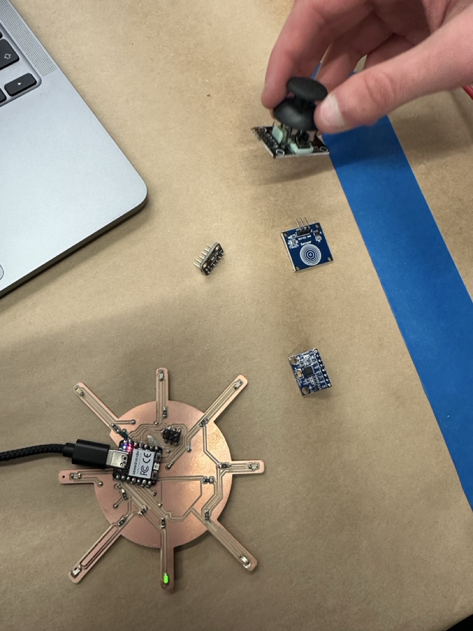
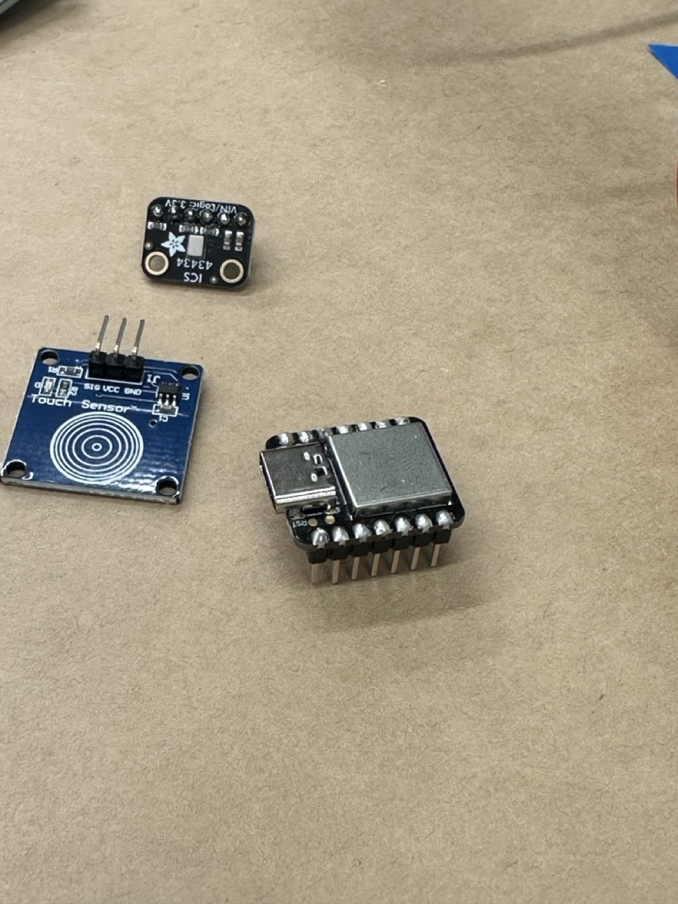
This week I experimented with different input devices to measure and respond to motion, touch and sound. I tested a joystick, accelerometer (MPU6050), capacitive touch sensor, and microphone (ICS43434). Each of these devices communicates differently with the microcontroller mainly through I2C (Inter-Integrated Circuit) or I2S (Inter-IC Sound) communication protocols.
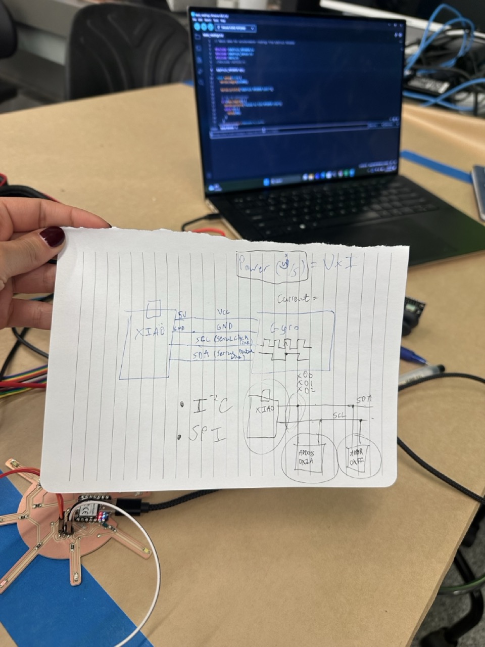
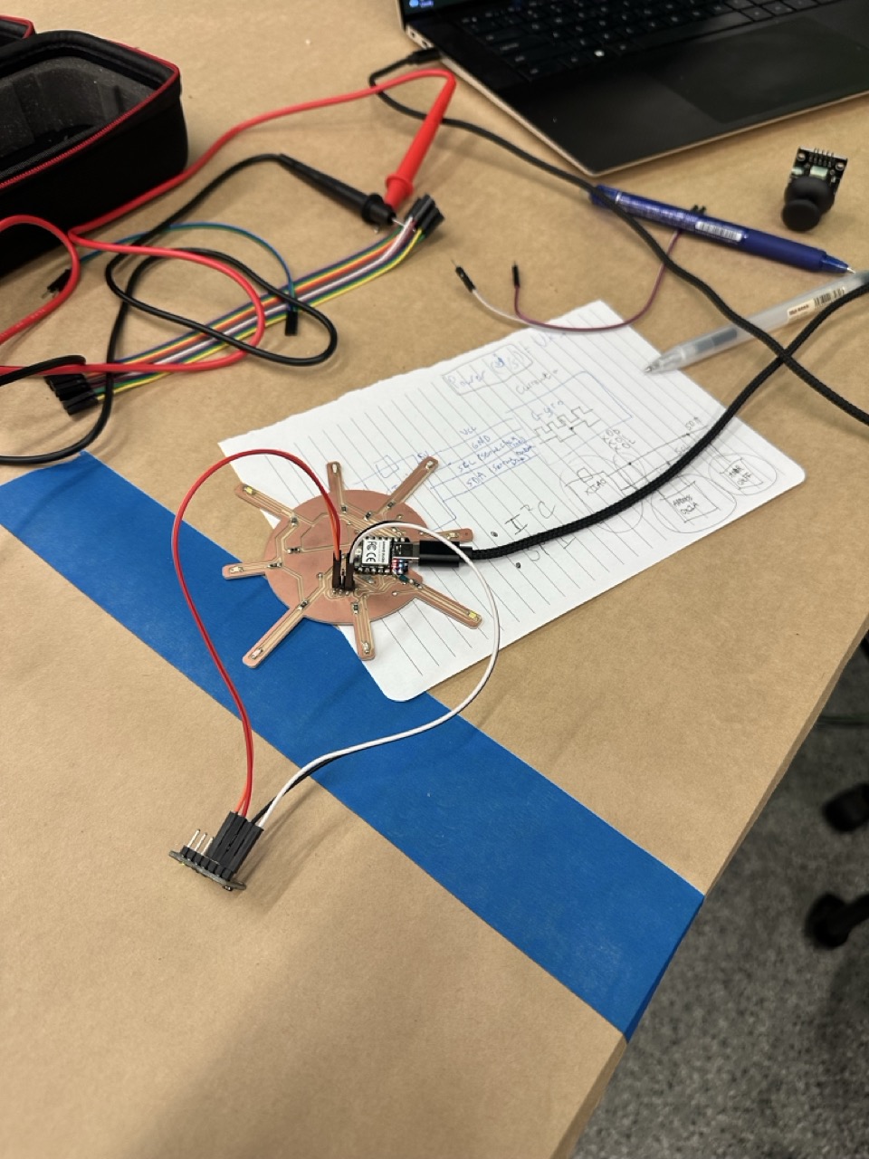
I wanted to connect sensors directly to my Sunlight PCB, which I had designed earlier with extra connectors for this week. While trying to add sensors I discovered that I had used my I2C pins (SDA and SCL) for LEDs. I didn't know yet that this would block communication with input devices (I am still learning).
That meant I couldn't use those pins for communication without either removing the LEDs or redesigning my board. After troubleshooting with JD (thanks so much JD) who spent hours walking me through it I decided to design a new PCB next week with correctly exposed I2C pins.
Even though this was a setback it was a valuable lesson in board design planning and communication mapping.
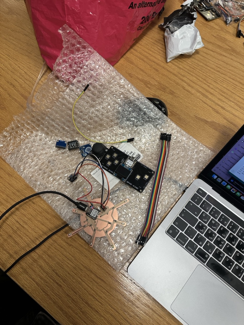
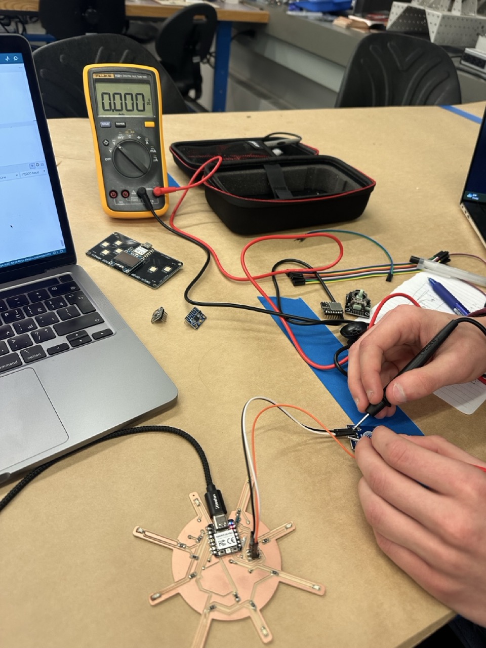
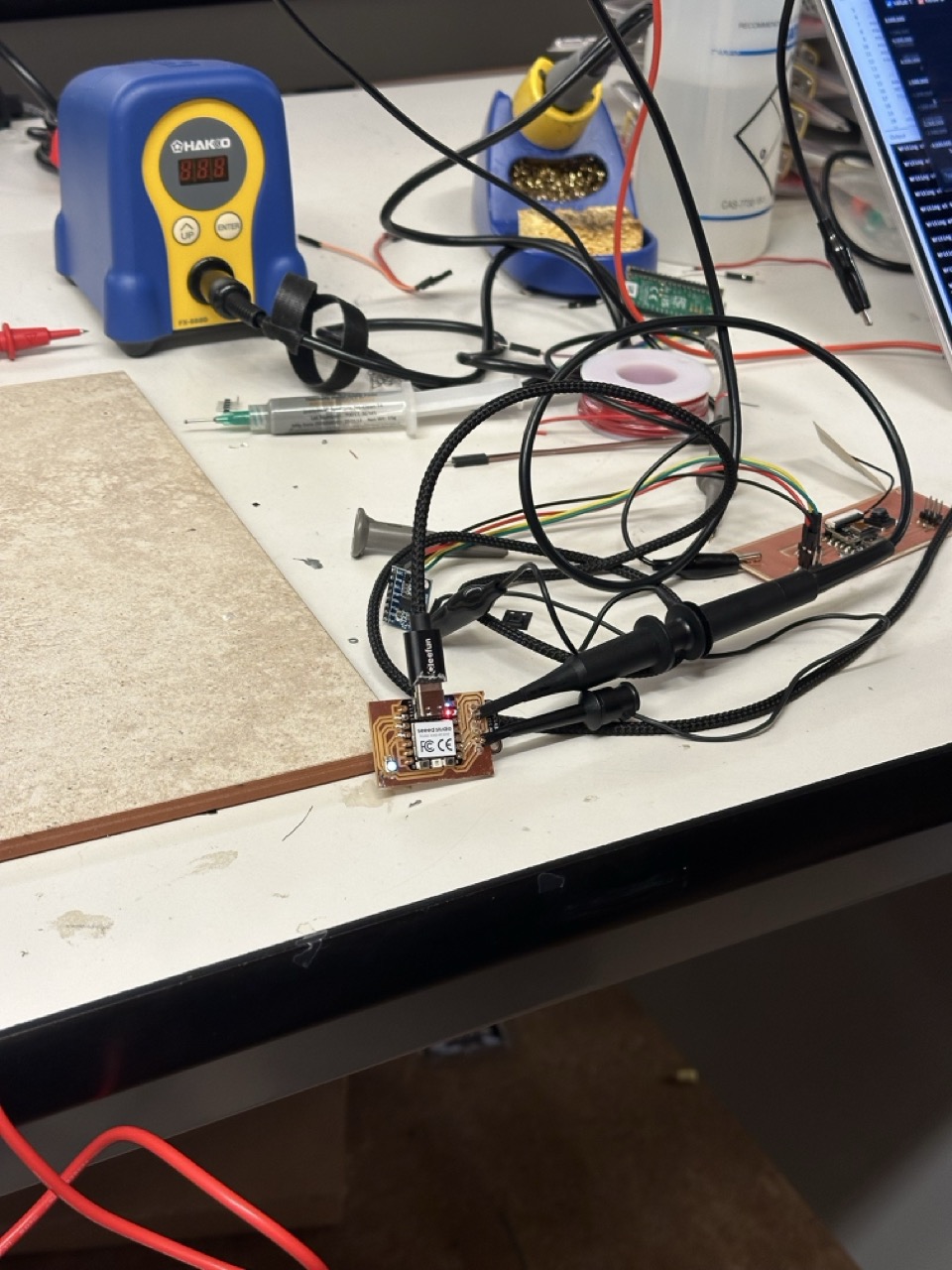
I soldered and wired different sensors to test them externally:
I learned how to correctly identify pins:
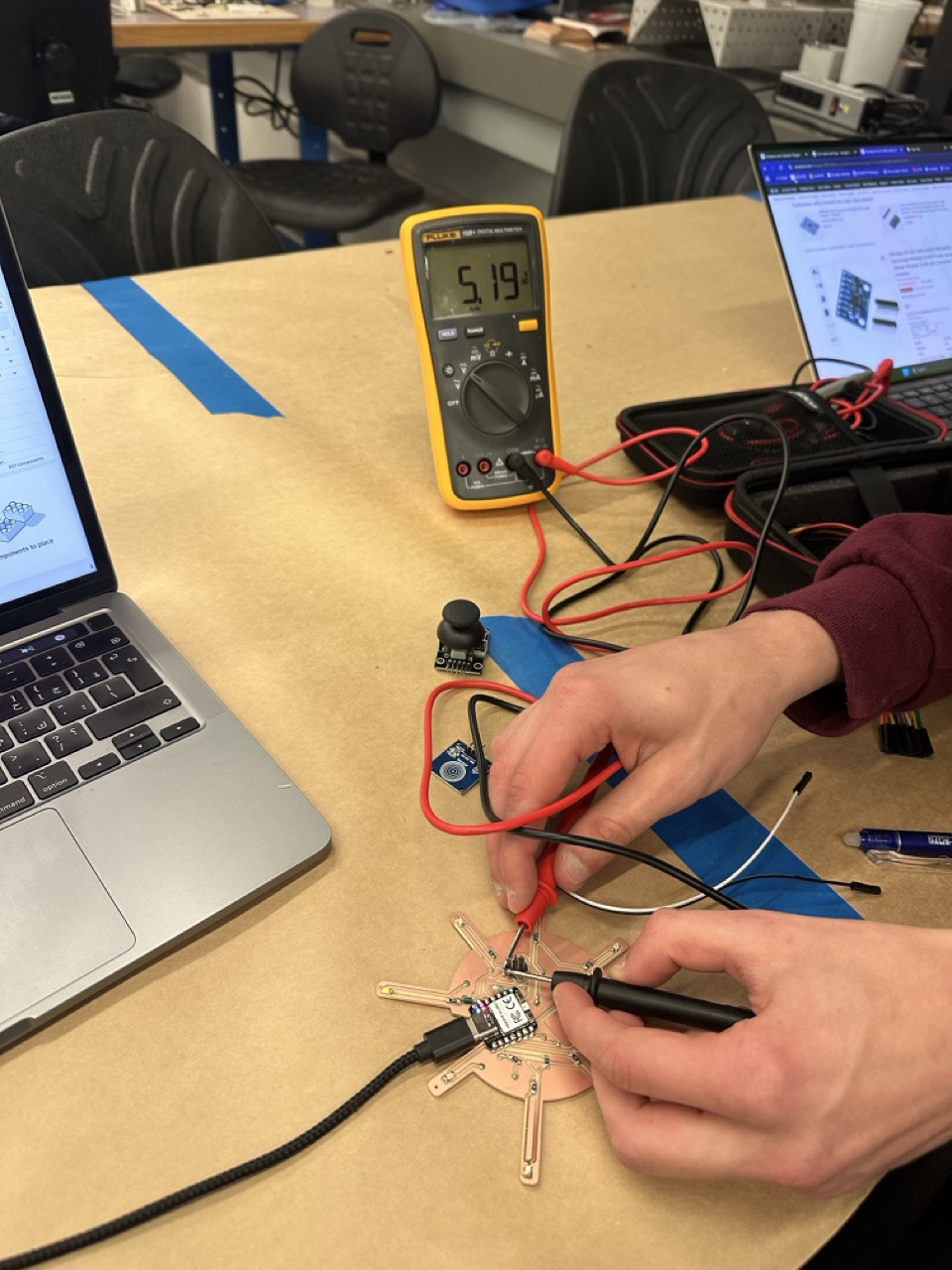
I also learned about male and female connectors, voltage conventions (black = GND, red = VCC) and how to use the multimeter to measure voltage and check for shorts in diode mode.
SAMD21 Attempt: We quickly soldered a SAMD21 board - tried to test sensors with I2C communication, but quickly resorted to Soft I2C (which also did not work 😊). This was another learning moment about hardware communication requirements.
From example sketches in Arduino IDE to sanity test / test Soft I2C:
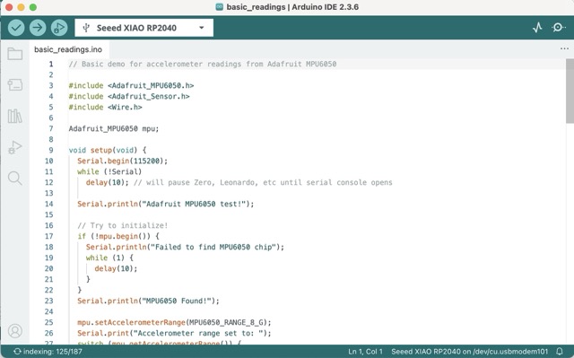
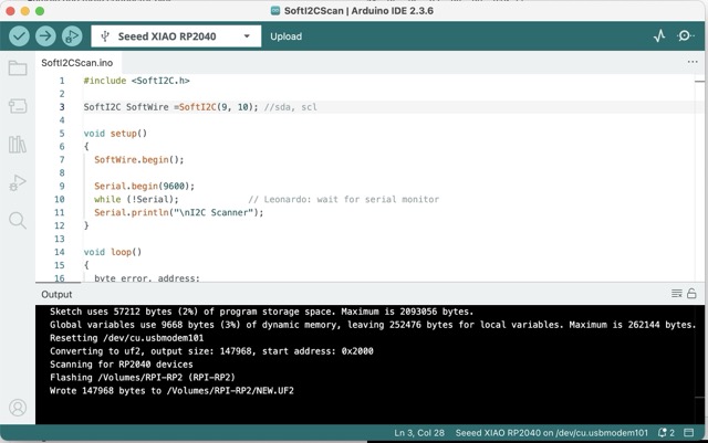
Using Arduino IDE, I:
Although the Soft I2C scan returned unstable addresses it helped me understand what happens when multiple devices share the same bus and how addressing conflicts appear.
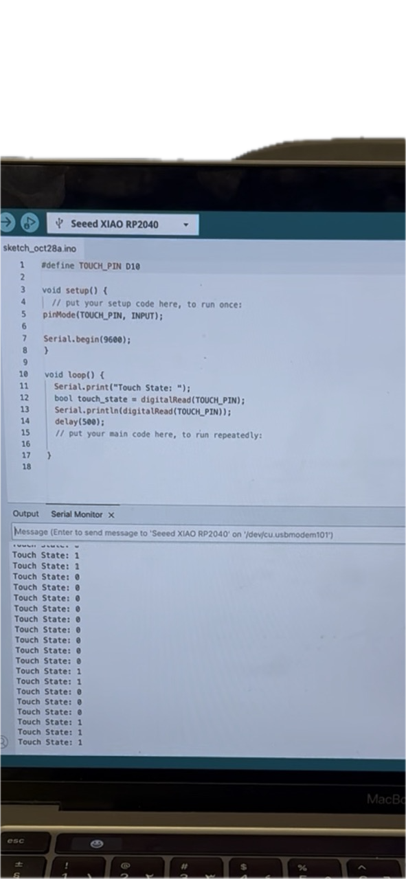
Simple code to test capacitive touch sensor input:
#define TOUCH_PIN D10

void setup() {
  pinMode(TOUCH_PIN, INPUT);
  Serial.begin(9600);
}

void loop() {
  Serial.print("Touch State: ");
  bool touch_state = digitalRead(TOUCH_PIN);
  Serial.println(touch_state);
  delay(500);
}I successfully got the capacitive touch sensor working on alternative pins - it turned the LEDs on when touched.
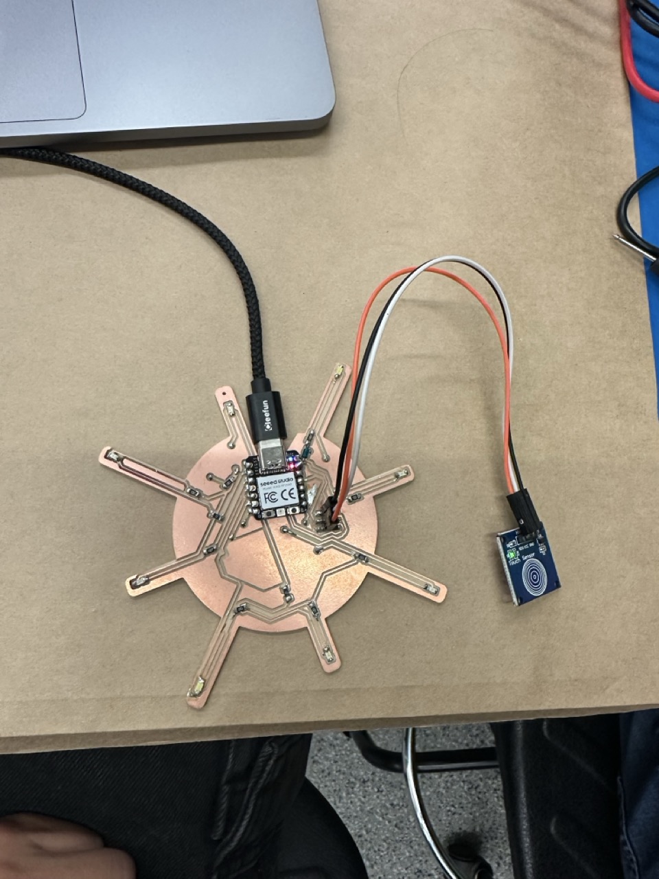
Recreated my first self-written code reading multiple input pins (D1–D8) on the Seeed XIAO RP2040. Each line in the Serial Monitor shows whether the touch input on each pin is active (1) or inactive (0).
int touchPins[] = {D1, D2, D3, D4, D5, D6, D7, D8};

void setup() {
  Serial.begin(9600);
  for (int i = 0; i < 8; i++) {
    pinMode(touchPins[i], INPUT);
  }
}

void loop() {
  for (int i = 0; i < 8; i++) {
    Serial.print(digitalRead(touchPins[i]));
    Serial.print(" ");
  }
  Serial.println();
  delay(300);
}Touch sensor working and controlling LEDs - success of the week:
For other sensors:
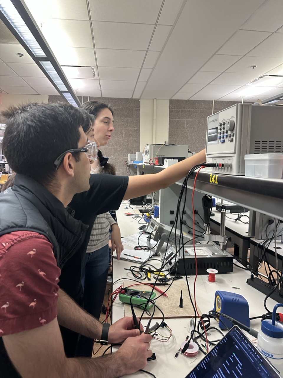
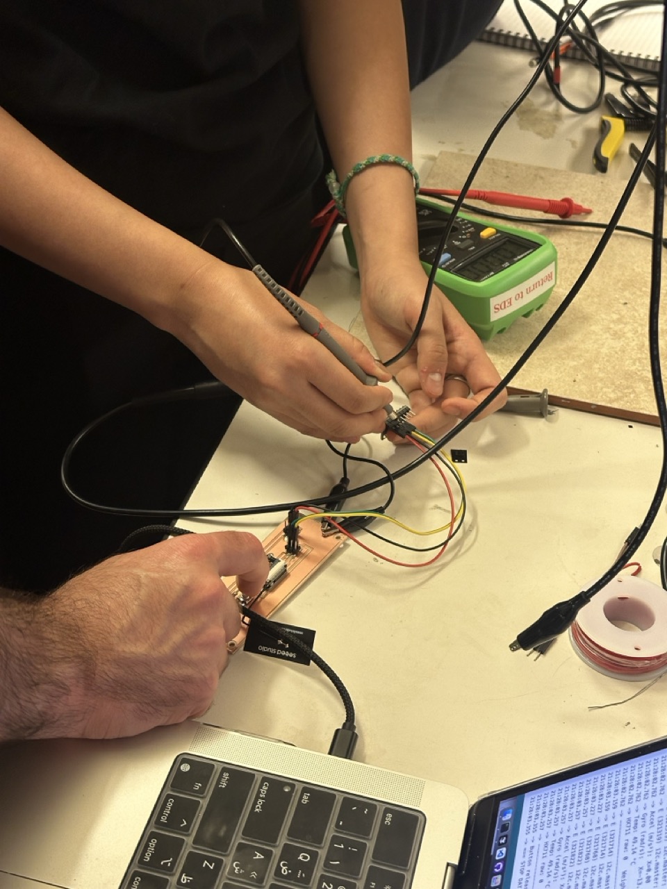
As a group we explored how to measure and visualize sensor signals using the oscilloscope. We tested three different input devices — a load cell, a microphone, and an IR phototransistor — to see how each behaved electrically and how their signals differed.
We began by connecting the oscilloscope probes correctly, grounding one probe to the board and attaching the other to the signal line. We then observed the live voltage patterns that each sensor produced.
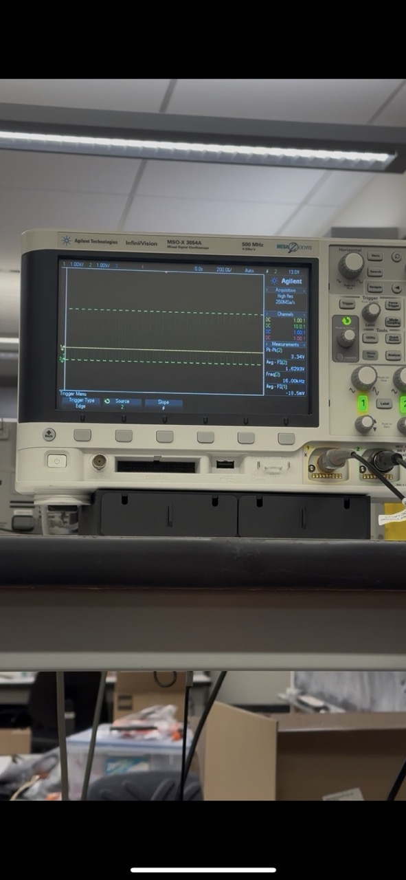
For the load cell, we saw small analog voltage changes corresponding to weight differences. The microphone produced continuous, fast-moving waveforms that represented sound vibrations in real time. With the IR phototransistor, we measured how light intensity affected the signal and captured clear clock signal patterns when testing its response.
Through this process we learned how to read and interpret analog vs digital waveforms, how to identify clock and data lines on I2C signals, and how different sensors communicate with the microcontroller. We also noticed that the act of probing itself can affect readings — especially for sensitive capacitive sensors, since the probe adds small capacitance to the circuit.
These experiments helped us connect theoretical communication protocols to real electrical behavior. The oscilloscope made data transmission visible and tangible — we could actually see how signals travel and change when the sensor responds.
Group work video documenting oscilloscope probing and signal analysis:
📸 Photo of clock signal testing for phototransistor (above). More images and results can be found on our Group Webpage.
This week was once again a big learning moment through failures and debugging. Even though many sensors didn't work as expected because of the I2C pin issue I learned more than I expected to.
Next time I'll map out my communication pins before designing the board to make sure I2C and analog pins stay free for sensors. I'll also test each sensor separately on a breadboard before committing it to the PCB design. I'd like to get the ICS43434 microphone fully working using I2S on the XIAO RP2040 and explore how multiple input devices can work together on one board.