Week 01 — Computer-Controlled Cutting
Parametric design, kerf-aware joints, and my first laser cut construction kit.
Assignment
Group Assignment:
- do your lab's safety training
- characterize your lasercutter's focus, power, speed, rate, kerf, joint clearance and types
Individual Assignment:
- cut something on the vinylcutter
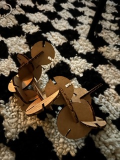
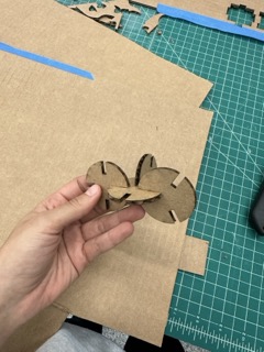
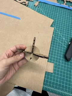
- design, lasercut, and document a parametric construction kit, accounting for the lasercutter kerf, which can be assembled in multiple ways
- extra credit: include elements that aren't flat
- extra credit: engrave as well as cut
Parametric Design & Computer-Controlled Cutting
This week marked my introduction to parametric design and digital fabrication. I learned to create construction kits using CAD software, understand material properties, and operate laser cutters. The journey from digital design to physical object was both challenging and rewarding.
Course Notes
HTMAA Philosophy: "If I can explain it simply, I really learned it." This week focused on bridging digital design with physical fabrication through parametric thinking and material understanding.
Key Resources: MIT HTMAA Course Page
Step 1 — Show up to the Fab Lab
Honestly, that's half the battle. Walk in. Look around. Breathe. One step at a time.
Step 2 — Open your laptop
Prepare for downloads, updates, logins you forgot, and many tutorial tabs. Still: open the laptop.
Step 3 — Ask for help
The TAs, instructors, and classmates are lifesavers. Everyone's been confused before—ask early, ask often.
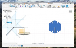
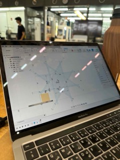
Step 4 — Download CAD tools
I tried Onshape first (felt simpler), then returned to Fusion 360—because if they can, I can too. That's the HTMAA mantra.
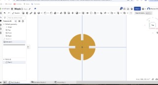
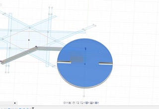
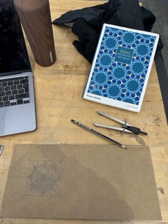
Step 5 — Draw circles and play
I started with a circle and just explored. First I chased an organic idea (DNA strand), then drifted toward Islamic geometry. Don't stress—even if classmates are producing intricate pieces. Tutorials help; experimenting helps too.
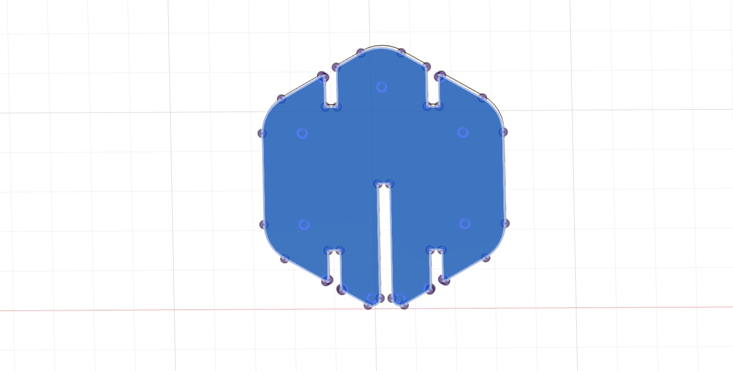
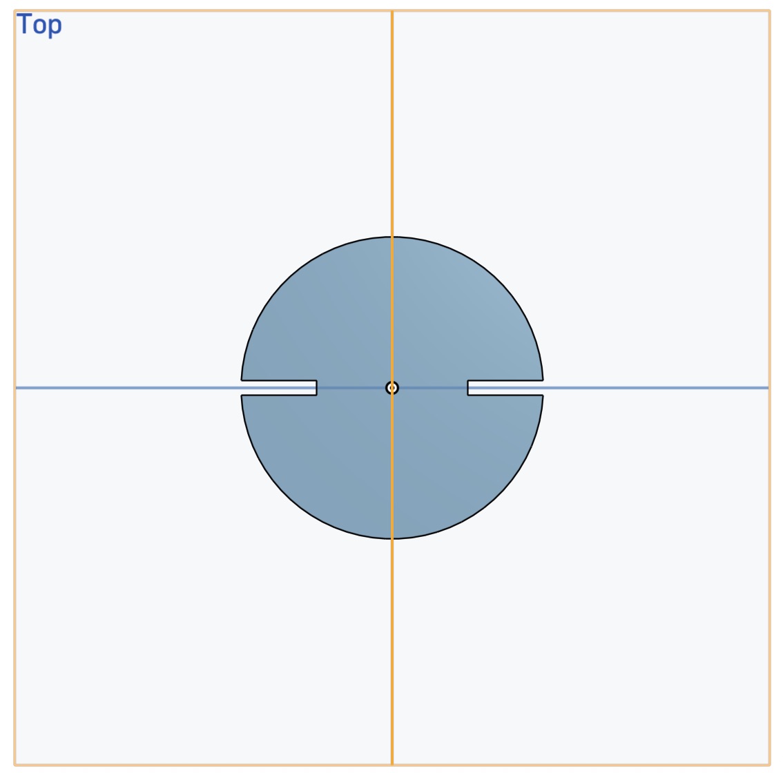
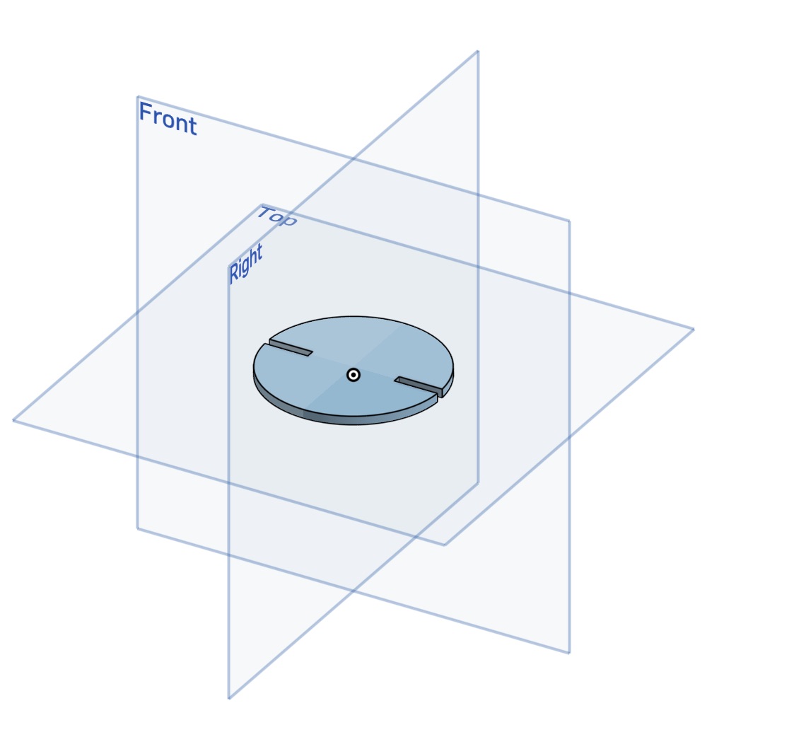
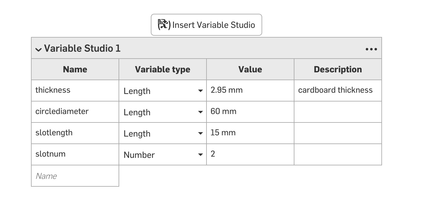
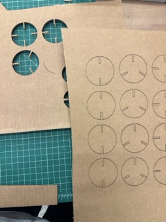
Step 6 — Set parameters (kerf-aware)
Parametric design = define variables so the model adapts. I used:
thickness = 2.95 mm, kerf_per_side = 0.05 mm, and a small
tolerance for fit. Slot width formula:
slot = thickness − 2×kerf_per_side − tolerance.
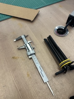
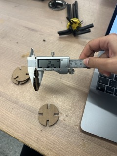
Cool tool moment: I loved using the caliper. It's a precise tool that measures thickness to hundredths of a millimeter. Tiny numbers, but they make the difference between a piece fitting or not. It made me feel like a "real" engineer for a second.
Step 7 — Export DXF and move to USB
Export your sketch profile as .dxf, copy to a USB, and head to the laser station.
Step 8 — Prep in Inkscape
Open the .dxf in Inkscape. Make sure cut lines are hairline and red
(whatever your lab's convention is). Print with ⌘+P, making sure the correct laser "printer" is selected.
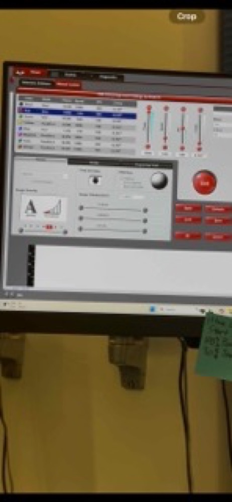
Step 9 — Laser software & safety
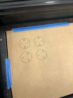
In the laser software, set speed/power/passes as recommended. Tape the cardboard, set focus with the peg, check bed height, and frame the job. Keep the lid closed; follow lab safety.
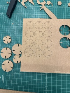
Step 10 — Press the green button
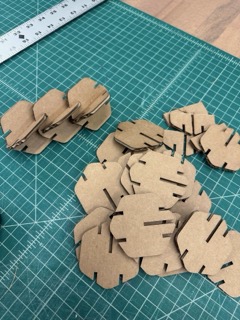
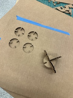
Watch the magic. Light + cardboard = your parametric kit. Some parts will fit, some won't—that's kerf teaching you.
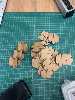
Results & Key Learnings
This week taught me the importance of precision in digital fabrication. Moving from organic sketches to parametric designs required a shift in thinking—from artistic intuition to mathematical precision. The kerf compensation lesson was particularly valuable, teaching me that successful fabrication requires understanding material behavior at the microscopic level.
Major Breakthroughs
- Parametric Thinking: Learning to design with variables rather than fixed dimensions
- Material Understanding: Measuring and compensating for laser kerf in joint design
- CAD Proficiency: Moving from basic sketches to complex parametric models
- Fabrication Confidence: Successfully operating laser cutting equipment
The transition from ring to bangle design taught me to adapt when initial concepts don't work with fabrication constraints. This flexibility and problem-solving approach became crucial for later weeks in HTMAA.
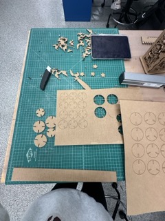
Second Go — Islamic Geometry Experiment (Trial & Error)
Round two: I tried drawing a more geometric pattern inspired by Islamic motifs. I'll add the sketches, updated parameters, and a short video here.
Lessons learned (click to expand)
- Small kerf changes matter at tight joints.
- Constraints early in CAD save time later.
- Keep scrap for quick test cuts before the "real" job.
Vinyl Sticker — Beginner's Guide
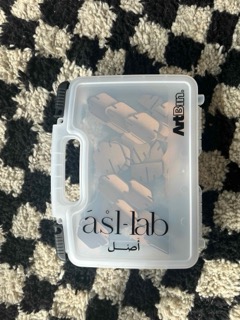
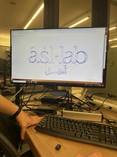
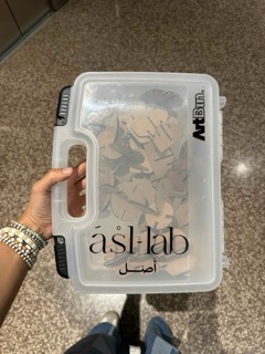
My first vinyl cut was the asl lab logo. The workflow uses mods:
- Prepare your artwork as a PNG/SVG (black lines on white background work best).
- Upload it to mods — you'll see the preview with blue toolpaths.
- Adjust the DPI to resize until it matches your intended size.
- Set up the machine: place vinyl, align the wheels under the white marks, lock the lever.
- Set the X/Y origin, then send the job from mods to the cutter.
- Once cut, lift the lever and pull the vinyl sheet forward.
- Weeding time: use tweezers to peel away the excess. It's fun (or very tedious) depending on your design.
- Apply transfer tape (sticky sheet) on top, burnish it, lift, and place the design where you want it.
About ASL Lab: "asl" means origin in Arabic. asl lab is my space for experimenting with photography, materiality, and sustainable processes — always going back to origins: of light, craft, and material knowledge.