Week 08: Output Devices
"What started off as petals ended up as the moon."
"What started off as petals ended up as the moon."
Group assignment: measure the power consumption of an output device
Individual assignment: add an output device to a microcontroller board I've designed and program it to do something
During programming weeks, I crumble. I dread them. These are the ones that test my patience, my logic and my ability to keep calm when the IDE refuses to compile.
This was Output Devices Week, which meant programming + electronics + timing errors = me questioning my life choices. It was also the week before my birthday and a full moon - cosmic alignment at its finest.
So instead of fighting the frustration, I leaned into it.
If I couldn't make my board work, I'd at least make poetry out of it.
"What was once the sun has now become the petals."
This week was equal parts exhaustion, experimentation and quiet victory.
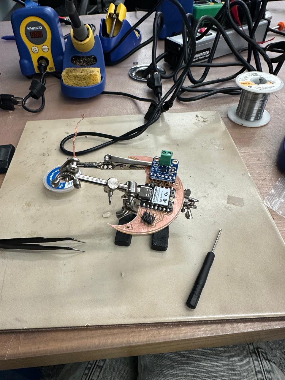
I began by designing what I called the Sun Board - a circular PCB that would eventually sprout attachable rays (or petals), each acting as its own input/output module.
The vision:
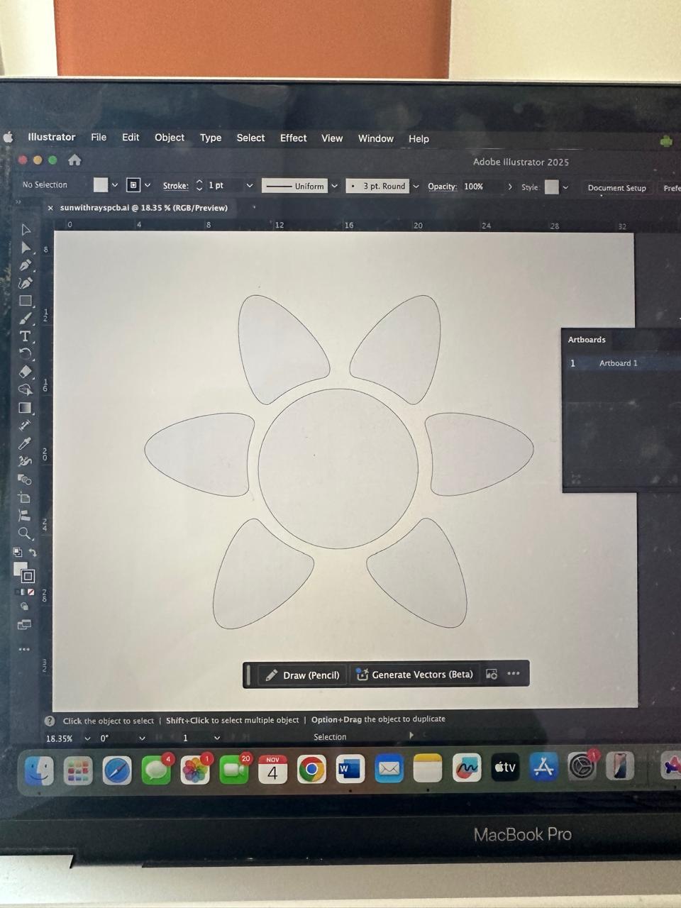
In my head it was a living dial of light - a responsive sun.
In reality, it was three days of anxiety, late-night design spirals and endless questions for Anthony and Aija (thank you both for your patience).
Eventually, time started running out and I realized I was designing myself into a corner.
I said the usual lie: "This time I'll keep it simple."
Naturally, I didn't.
| Stage | Tool / Skill | Purpose |
|---|---|---|
| Concept modeling | Illustrator + Fusion 360 | PCB outlines |
| Circuit + code | Arduino IDE | Programming RP2040 (LEDs, I²S amp) |
| Fabrication | The Other Mill | Milling and engraving |
| Verification | Multimeter | Continuity testing |
| Documentation | Cursor / HTML / Markdown | Class website update |
By Tuesday night, nothing worked. Anthony calmly said, "Just make a simple test board."
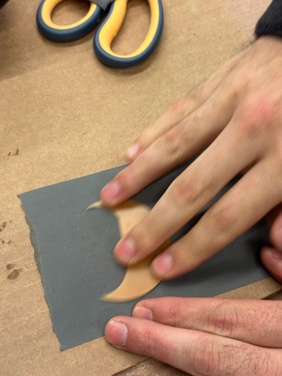
So, naturally, I made a moon instead.
It was the week before my birthday, a full moon was approaching and I decided to embrace it. And what's more to add another celestial object to the collection I am building.
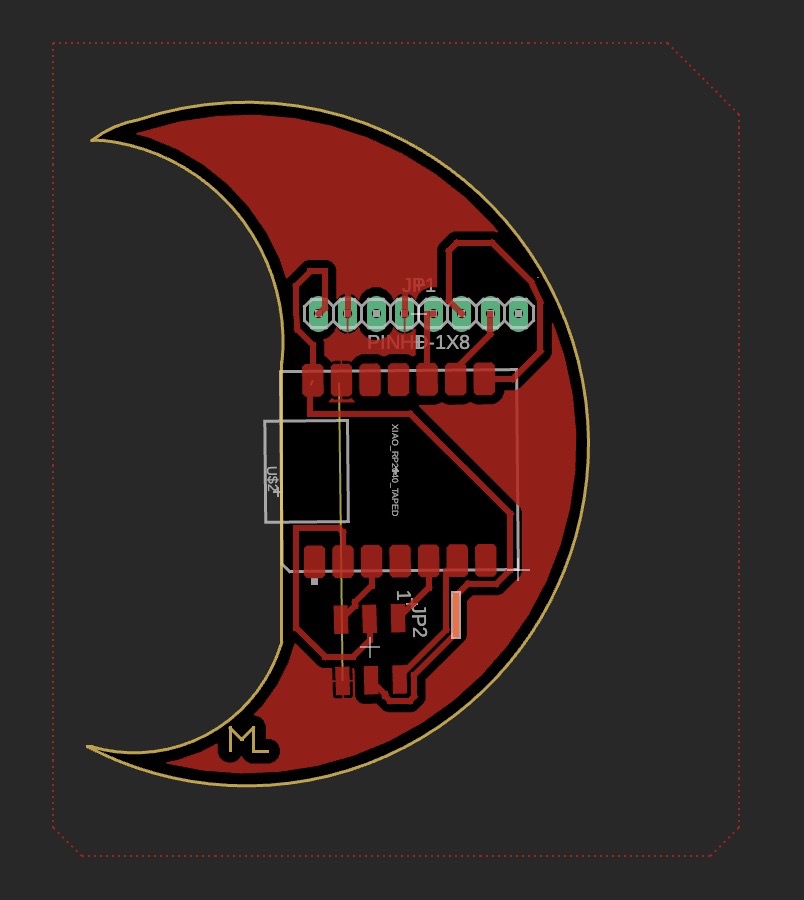
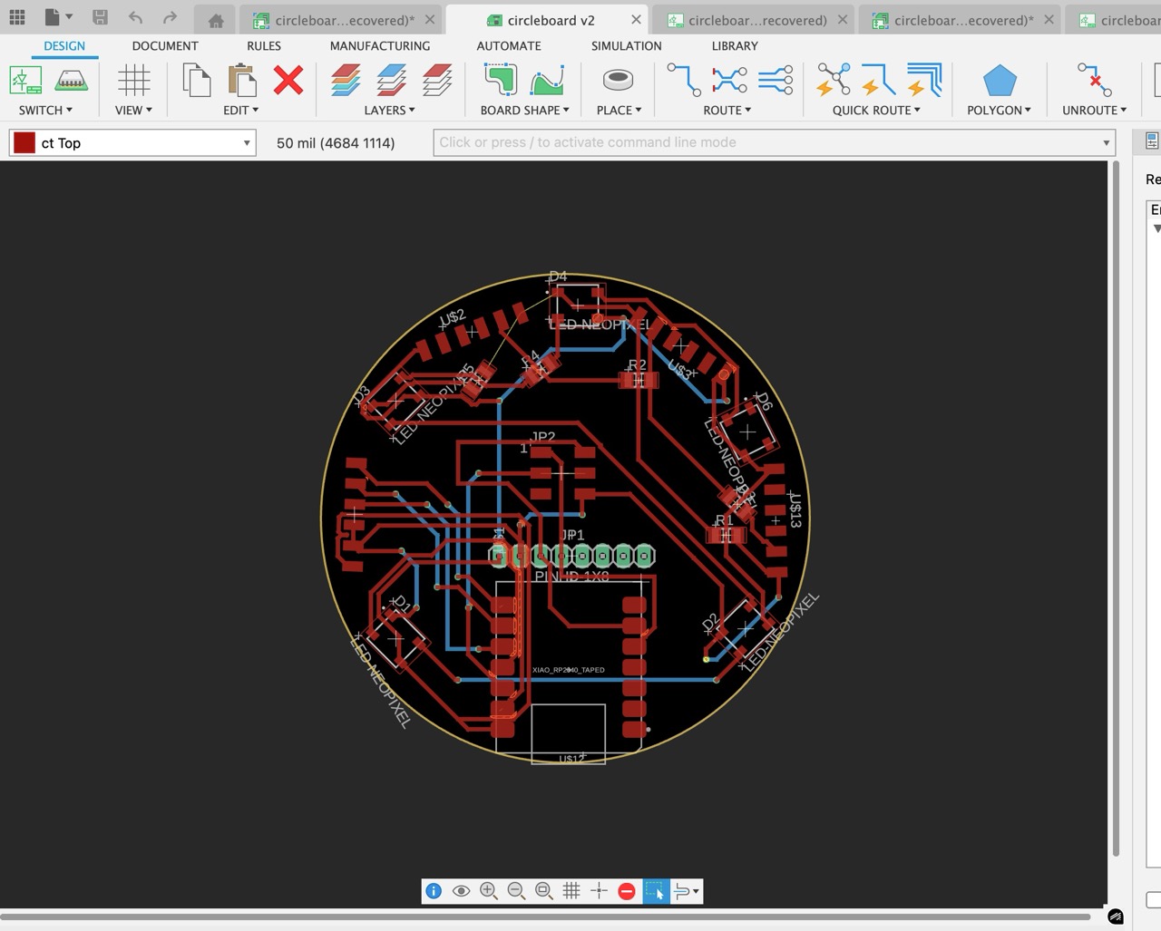
Soldered everything. It was a single-sided board. No copper. So I made a mistake of soldering one of the through board 1x8 pins for the amplifier to the back.
Re-soldered between the floating plastic front of board thankfully there was space from the top (thank you Anthony for staying late again).
Checked continuity with multimeter - finally connected ✔️
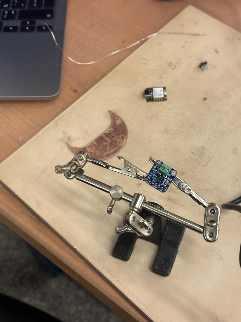
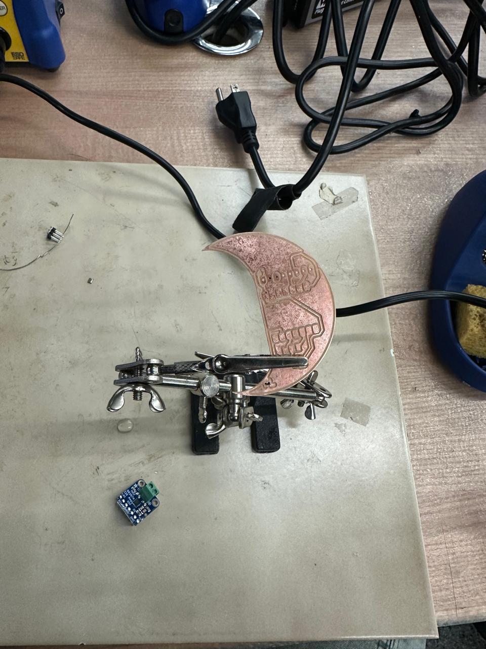
B. Audio Output Test - MAX98357A (I²S Amplifier) connected to the speaker
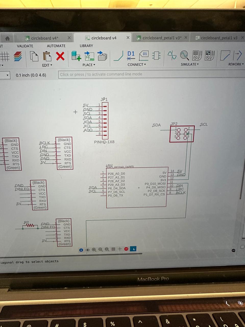
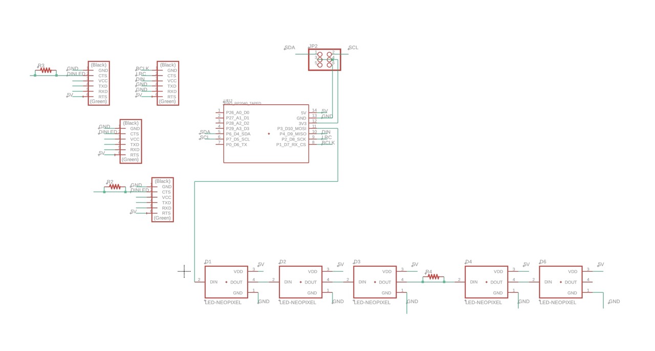
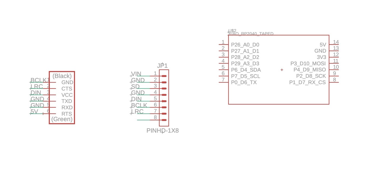
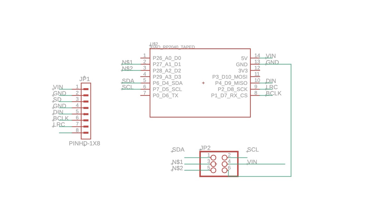
After realizing my Sun Board design was overly complex, I simplified it into what became the Moon Board - a compact RP2040 board with an 8-pin header for a MAX98357A amplifier.
The idea was to test a straightforward audio output device: generate tone or simple sound playback through the digital I²S interface.
| Signal | RP2040 Pin |
|---|---|
| BCLK | GP26 |
| LRCLK | GP27 |
| DIN | GP28 |
I wired the amplifier according to the datasheet and tried uploading an example I²S sketch that should have produced simple tones.
Compilation repeatedly failed with these errors:
expected unqualified-id before '.' token
'I2S_PHILIPS_MODE' was not declared in this scope
The issue wasn't with wiring - it was with the Arduino core.
I was still using the Arduino Mbed RP2040 core, which doesn't include I²S support.
After some research (and frustration), I learned that I needed to install Earle Philhower's Raspberry Pi RP2040 Boards core, which properly implements the I²S library.
Installation required adding this URL under Preferences → Additional Boards Manager URLs:
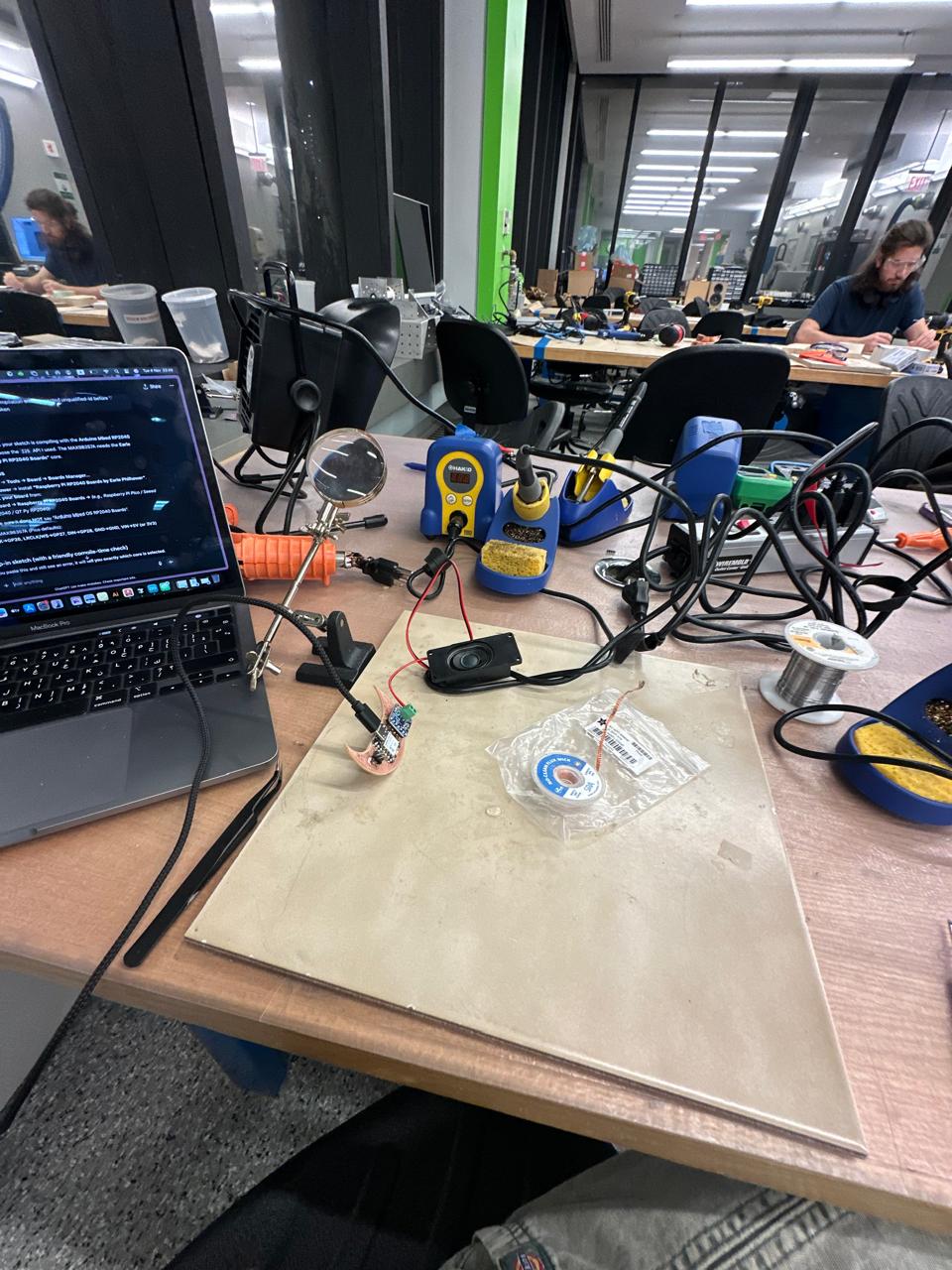
https://github.com/earlephilhower/arduino-pico/releases/download/global/package_rp2040_index.jsonI pivoted from the Sun-board to a simpler Moon board with an 8-pin header for the MAX98357A. I wired I²S, tried to play a melody test, hit compile errors, realized I was on the wrong core, installed the Earle Philhower RP2040 core and then the same sketch compiled cleanly. I stopped there (late night), so no audible output yet - but next run should play.
On Seeed XIAO RP2040, a good mapping is BCLK=D2, LRCLK=D3, DIN=D1 (update in code below).
Copy into a new sketch and upload after selecting the Philhower RP2040 board.
/*
  MAX98357A + RP2040 (I2S) - Melody + Sweep Test
  Board package: Earle Philhower "Raspberry Pi RP2040 Boards"
  Default pins (Raspberry Pi Pico):
    BCLK  -> GP26
    LRCLK -> GP27
    DIN   -> GP28
  If using Seeed XIAO RP2040, uncomment the XIAO block below.
*/

#include <Arduino.h>
#include <I2S.h>
#include <math.h>

// ---------- PIN SETUP ----------
// Pico defaults:
const int I2S_BCLK_PIN  = 26; // GP26
const int I2S_LRCLK_PIN = 27; // GP27 (WS)
const int I2S_DOUT_PIN  = 28; // GP28 (to MAX98357A DIN)

// // Seeed XIAO RP2040 (uncomment if using XIAO):
// const int I2S_BCLK_PIN  = D2;
// const int I2S_LRCLK_PIN = D3;
// const int I2S_DOUT_PIN  = D1;

// ---------- AUDIO SETTINGS ----------
const int   SAMPLE_RATE     = 44100;   // 44.1 kHz
const int   BITS_PER_SAMPLE = 16;      // 16-bit
const float VOLUME          = 0.6f;    // 0.0–1.0

// ---------- NOTE TABLE ----------
struct Note { float freq; int ms; };

#define N_C4  261.63f
#define N_D4  293.66f
#define N_E4  329.63f
#define N_F4  349.23f
#define N_G4  392.00f
#define N_A4  440.00f
#define N_B4  493.88f
#define N_C5  523.25f

Note melody[] = {
  {N_C4,400}, {N_C4,400}, {N_G4,400}, {N_G4,400},
  {N_A4,400}, {N_A4,400}, {N_G4,800},
  {N_F4,400}, {N_F4,400}, {N_E4,400}, {N_E4,400},
  {N_D4,400}, {N_D4,400}, {N_C4,800}
};

const int MELODY_LEN = sizeof(melody)/sizeof(melody[0]);

// ---------- HELPERS ----------
inline void writeStereo(int16_t s) {
  I2S.write(s); // Left
  I2S.write(s); // Right
}

void playSilence(int ms) {
  const int frames = (SAMPLE_RATE * ms) / 1000;
  for (int i = 0; i < frames; i++) writeStereo(0);
}

void playTone(float freqHz, int ms) {
  if (freqHz <= 0.0f) { playSilence(ms); return; }
  const int frames = (SAMPLE_RATE * ms) / 1000;
  const float phaseInc = (2.0f * PI * freqHz) / SAMPLE_RATE;
  const int16_t amp = (int16_t)(32767.0f * VOLUME);
  float phase = 0.0f;
  for (int i = 0; i < frames; i++) {
    int16_t sample = (int16_t)(sinf(phase) * amp);
    writeStereo(sample);
    phase += phaseInc;
    if (phase >= 2.0f * PI) phase -= 2.0f * PI;
  }
}

void playMelody() {
  for (int i = 0; i < MELODY_LEN; i++) {
    playTone(melody[i].freq, melody[i].ms);
    playSilence(20); // short gap between notes
  }
}

void sweepTest(float startHz, float endHz, int ms) {
  const int frames = (SAMPLE_RATE * ms) / 1000;
  float f = startHz;
  const float df = (endHz - startHz) / frames;
  float phase = 0.0f;
  const int16_t amp = (int16_t)(32767.0f * (VOLUME * 0.8f));
  for (int i = 0; i < frames; i++) {
    const float phaseInc = (2.0f * PI * f) / SAMPLE_RATE;
    int16_t sample = (int16_t)(sinf(phase) * amp);
    writeStereo(sample);
    phase += phaseInc;
    if (phase >= 2.0f * PI) phase -= 2.0f * PI;
    f += df;
  }
}

// ---------- SETUP/LOOP ----------
void setup() {
  Serial.begin(115200);
  delay(200);
  I2S.setBCLK(I2S_BCLK_PIN);
  I2S.setLRCLK(I2S_LRCLK_PIN);
  I2S.setDOUT(I2S_DOUT_PIN);
  if (!I2S.begin(I2S_PHILIPS_MODE, SAMPLE_RATE, BITS_PER_SAMPLE)) {
    Serial.println("I2S.begin() failed - check Philhower core and pins.");
    while (1) delay(1000);
  }
  playSilence(50);
  playMelody();
  playSilence(200);
  sweepTest(200.0f, 4000.0f, 3000);
  playSilence(200);
}

void loop() {
  delay(1500);
  playMelody();
  delay(1500);
}
Re-installing fixed the "platform not found" issue and the code finally compiled ✔️
Unfortunately, by that point it was 11:30 p.m. and I didn't have time (or energy) to continue testing the speaker. No audible output yet - but I now know what was wrong and how to fix it next time.
Before Output Week fully derailed into moonlight and solder fumes, I had developed a small wearable concept - an LED-based time-management device.
The idea came from wanting to visualize focus and rest cycles through light, instead of timers or screens.
Each LED on the ring (or petal) would represent a unit of time - say, ten minutes.
The lights would slowly move around the circle as time passed, glowing brighter during focus intervals and dimmer during breaks.
It was a small gesture - a rhythm light, a clock that breathes - designed to live on the wrist or near a workspace.
Technically, it's an LED-animation and timing problem, which makes it perfect for output week:
Even though I didn't get to fabricate this version yet, the old board I made earlier - the Sun/Petal board - still supports the concept:
So yes, this can absolutely still be done.
It's a soft bridge between the Sun Board (as concept) and the Moon Board (as practice) - both celestial, both about cycles, rhythm and time.
Last week I was out of town and only had time to wire a capacitive-touch sensor as an input and get my NeoPixels working as outputs. Technically, that already bridged input→output: touch was toggling a light state.
This week I'm advancing that idea into a tiny LED time-management wearable using my old Sun/Petal board (thanks to Anthony for the reality check that I can still reuse it while the "Sun Board" debug continues).
Intent: use the NeoPixel ring as a soft, ambient timer (focus/break cycles). Each LED = a time "tick." Colors/brightness encode state (focus vs. break) and a button/touch can start/pause/reset.
Hardware I Already Have
Mapping
Note on the XIAO: the BOOT button isn't a general GPIO for sketches. Use a spare pin and a small pushbutton instead.
Non-blocking (uses millis()), simple state machine (IDLE/FOCUS/BREAK)
Touch or button: start/pause/reset
Progress arcs the ring; colors: focus=warm white, break=blue
Easily change durations
Libraries: Adafruit_NeoPixel (Library Manager)
/*  LED Time Manager - RP2040 + NeoPixel
    Works on Raspberry Pi Pico or Seeed XIAO RP2040 with Adafruit_NeoPixel.
    - Each LED is a time tick; ring shows progress around the circle.
    - States: IDLE, FOCUS, BREAK. Touch/button to start/pause/reset.

    Wiring (typical):
      NeoPixel 5V  -> 5V
      NeoPixel GND -> GND (shared with MCU)
      NeoPixel DIN -> NEOPIXEL_PIN (through 330Ω recommended)
      Large electrolytic across 5V/GND near LEDs (e.g., 470µF)

      Touch sensor SIG (e.g., TTP223) -> TOUCH_PIN (digital in)
      Optional momentary button -> BUTTON_PIN to GND (use INPUT_PULLUP)

    IMPORTANT for XIAO RP2040:
      Use a spare GPIO for BUTTON_PIN. The on-board BOOT is not a normal GPIO.
*/

#include <Adafruit_NeoPixel.h>

// ---------- USER CONFIG ----------
#define LED_COUNT       16             // set to your ring count
#define NEOPIXEL_PIN    7              // e.g., XIAO RP2040 D7 (change as needed)
#define TOUCH_PIN       2              // digital input from touch sensor (or set to -1 to disable)
#define BUTTON_PIN      1              // external button to GND; uses INPUT_PULLUP (-1 to disable)
#define BRIGHTNESS      60             // 0-255 overall limit

// Durations (milliseconds). Example: 10 min focus / 2 min break
const unsigned long FOCUS_MS = 10UL * 60UL * 1000UL;
const unsigned long BREAK_MS =  2UL * 60UL * 1000UL;

// Colors (RGB)
uint32_t COLOR_FOCUS = 0xFFF0C0;       // warm white
uint32_t COLOR_BREAK = 0x60A0FF;       // soft blue
uint32_t COLOR_IDLE  = 0x100810;       // very dim, "breathing" base

// ---------- GLOBALS ----------
Adafruit_NeoPixel strip(LED_COUNT, NEOPIXEL_PIN, NEO_GRB + NEO_KHZ800);

enum State { IDLE, FOCUS, BREAK, PAUSED };
State state = IDLE;

unsigned long stateStart = 0;
unsigned long pauseAccum = 0;
bool paused = false;

unsigned long lastBreath = 0;
int breathDir = 1;
uint8_t breathVal = 10;

bool lastTouch = false;
bool lastButton = true; // with INPUT_PULLUP, idle is HIGH

// ---------- HELPERS ----------
bool readTouch() {
  if (TOUCH_PIN < 0) return false;
  int v = digitalRead(TOUCH_PIN);
          // TTP223 can be active HIGH or LOW depending on config. If my module is active LOW,
          // invert here:
          return (v == HIGH); // flip to (v == LOW) if needed for my board
}

bool readButtonPressed() {
  if (BUTTON_PIN < 0) return false;
  // INPUT_PULLUP: pressed = LOW
  int v = digitalRead(BUTTON_PIN);
  return (v == LOW);
}

void clearStrip() {
  for (int i = 0; i < LED_COUNT; i++) strip.setPixelColor(i, 0);
}

void showProgress(uint32_t col, float t01) {
  // t01: 0..1
  int lit = (int)(t01 * LED_COUNT + 0.5f);
  if (lit < 0) lit = 0;
  if (lit > LED_COUNT) lit = LED_COUNT;
  clearStrip();
  for (int i = 0; i < lit; i++) strip.setPixelColor(i, col);
  strip.show();
}

void showAll(uint32_t col) {
  for (int i = 0; i < LED_COUNT; i++) strip.setPixelColor(i, col);
  strip.show();
}

uint32_t scaleColor(uint32_t c, uint8_t scale) {
  uint8_t r = (uint8_t)((c >> 16) & 0xFF);
  uint8_t g = (uint8_t)((c >> 8) & 0xFF);
  uint8_t b = (uint8_t)(c & 0xFF);
  r = (uint8_t)((r * scale) / 255);
  g = (uint8_t)((g * scale) / 255);
  b = (uint8_t)((b * scale) / 255);
  return strip.Color(r, g, b);
}

void showBreathing(uint32_t baseColor) {
  // simple triangle-wave breathing
  unsigned long now = millis();
  if (now - lastBreath >= 20) {
    lastBreath = now;
    breathVal += breathDir;
    if (breathVal >= 60) breathDir = -1;
    if (breathVal <= 8)  breathDir = +1;
    uint32_t c = scaleColor(baseColor, breathVal);
    showAll(c);
  }
}

unsigned long stateDurationMs(State s) {
  if (s == FOCUS) return FOCUS_MS;
  if (s == BREAK) return BREAK_MS;
  return 0;
}

float stateProgress01() {
  unsigned long now = millis();
  unsigned long elapsed = now - stateStart - pauseAccum;
  unsigned long dur = stateDurationMs(state);
  if (dur == 0) return 0.0f;
  if (elapsed >= dur) return 1.0f;
  return (float)elapsed / (float)dur;
}

void enterState(State s) {
  state = s;
  stateStart = millis();
  pauseAccum = 0;
  paused = false;
}

void togglePause() {
  if (state == IDLE) return;
  paused = !paused;
  static unsigned long pauseStart = 0;
  if (paused) {
    pauseStart = millis();
  } else {
    pauseAccum += (millis() - pauseStart);
  }
}

void nextState() {
  if (state == FOCUS) enterState(BREAK);
  else if (state == BREAK) enterState(IDLE);
  else enterState(FOCUS); // from IDLE/PAUSED
}

// ---------- SETUP/LOOP ----------
void setup() {
  strip.begin();
  strip.setBrightness(BRIGHTNESS);
  strip.show();

  if (TOUCH_PIN >= 0) {
    pinMode(TOUCH_PIN, INPUT); // change to INPUT_PULLUP if my touch module needs it
  }
  if (BUTTON_PIN >= 0) {
    pinMode(BUTTON_PIN, INPUT_PULLUP); // button to GND
  }

  enterState(IDLE);
}

void handleInputs() {
  // Edge detection for touch
  bool t = (TOUCH_PIN >= 0) ? readTouch() : false;
  if (t && !lastTouch) {
    // touch rising edge: cycle behavior
    if (state == IDLE)      enterState(FOCUS);
    else if (state == FOCUS) togglePause(); // pause/resume focus
    else if (state == BREAK) togglePause(); // pause/resume break
  }
  lastTouch = t;

  // Edge detection for button
  bool bPressed = (BUTTON_PIN >= 0) ? readButtonPressed() : false;
  if (bPressed && lastButton) {
    // on button press: if paused → resume; if running → skip; if idle → start focus
    if (state == IDLE) enterState(FOCUS);
    else if (paused)   togglePause();
    else               nextState(); // skip to next state
  }
  lastButton = !bPressed; // store last level (HIGH when not pressed)
}

void loop() {
  handleInputs();

  if (state == IDLE) {
    // breathe dim to indicate ready
    showBreathing(COLOR_IDLE);
    return;
  }

  if (paused) {
    // show frozen progress, low brightness
    float t01 = stateProgress01();
    uint32_t c = (state == FOCUS) ? scaleColor(COLOR_FOCUS, 40) : scaleColor(COLOR_BREAK, 40);
    showProgress(c, t01);
    delay(20);
    return;
  }

  // Running
  float t01 = stateProgress01();
  uint32_t c = (state == FOCUS) ? COLOR_FOCUS : COLOR_BREAK;
  showProgress(c, t01);

  // Transition complete → next state
  if (t01 >= 1.0f) {
    if (state == FOCUS) enterState(BREAK);
    else if (state == BREAK) enterState(IDLE);
  }

  delay(20); // small refresh delay
}Last week, even though I was traveling, I wired a capacitive-touch sensor as input and got my NeoPixels working as outputs. This week I turned that into a small LED time-management wearable: a ring that visualizes focus and break periods with color and progress. After talking with Anthony, I realized I can keep using my old Sun/Petal board to test this while I keep troubleshooting the "Sun Board." It's simple, ambient and it closes the loop between input (touch) and output (light).
The group task for Week 8 was to measure the power consumption of output devices and understand how different loads behave electrically - LEDs, motors and audio drivers in particular.
Although I wasn't directly involved in running the experiments (it was an extremely full week between my own board troubleshooting and midterm prep), I reviewed my group's data and notes and discussed their results afterwards to understand the key observations.
This week was messy, cosmic and strangely fitting. I began with a Sun Board, ended with a Moon Board and somewhere in between learned how to debug, solder and surrender.
Even though I wasn't on the measuring bench, reviewing the group's results helped connect theory to what I was experiencing with my own boards - unstable power, flickering LEDs and audio glitches all started to make more sense once I understood how power behaves under load. It was a good reminder that every output device begins as a story about energy moving through a system.
Each mistake turned into a line of code - or a line of poetry - and somehow that feels right.
Even if the sun never rose, at least the moon still glows.
(Three meetings ≈ 2-3 hrs each - thank you JD):