Week 02 — Electronics & Embedded Programming
Inputs → code → outputs. From a heartbeat "tick" to my own touch-controlled plant on an OLED.
Assignment
Group Assignment:
- demonstrate and compare the toolchains and development workflows for available embedded architectures
Individual Assignment:
- browse through the data sheet for a microcontroller
- write and test a program for an embedded system using a microcontroller to interact (with local input &/or output devices) and communicate (with remote wired or wireless connections)
- extra credit: try different languages &/or development environments
How to Survive Soldering & Embedded Programming
Welcome to my crash course in being confused, clicking too many things, and eventually making something!
This is my beginner-friendly guide to going from "I have no idea what's happening" to real, working code on hardware.
Note: We're all learning. It's new, and that's okay.
1) What is embedded programming
Embedded programming is writing code for specialized computer systems that are embedded into devices to control their behavior. Unlike general-purpose computers (like laptops or desktops), embedded systems are designed for specific tasks and often operate with limited resources—small amounts of memory, minimal processing power, and direct hardware control. The code runs on microcontrollers or microprocessors that are integrated into the device itself, allowing it to sense inputs, process data, and control outputs in real-time.
Lecture notes (Anthony): stay at 3.3 V on RP2040 pins, prove life with a blink/serial test first, then add features gradually. Good soldering is part of debugging.
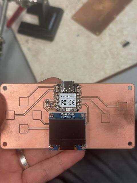
2) Soldering (intro + my process)
Goal: each castellated pad is fully wetted—joining the module edge pad and my PCB pad. I tinned the iron, used flux, tack-soldered corners, then ran a small bead across each edge. Final step: continuity checks.
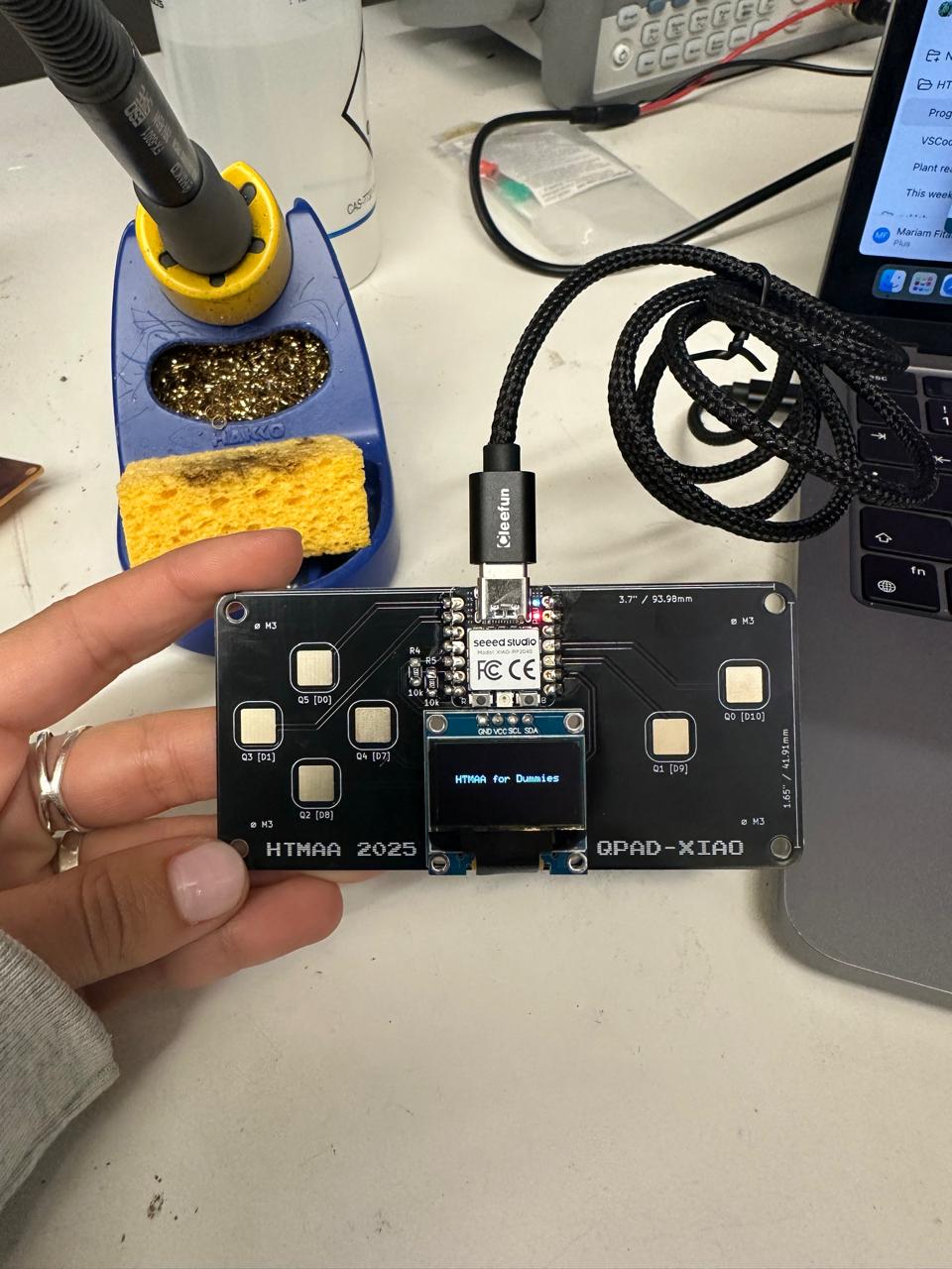
3) Initial sanity tests (thanks, Quentin)
I validated the hardware using Quentin's minimal Arduino sketches. These prove three layers quickly: microcontroller runs code (blink), I²C display works (hello text), and touch pads respond (cap sense + LED example).
Testing
3.1 Blink (is the microcontroller alive?)
// Blink — basic liveness test (XIAO RP2040)
void setup(){
  pinMode(LED_BUILTIN, OUTPUT);
}
void loop(){
  digitalWrite(LED_BUILTIN, HIGH); delay(500);
  digitalWrite(LED_BUILTIN, LOW);  delay(500);
}
If this blinks, the RP2040 is running code and GPIO works.
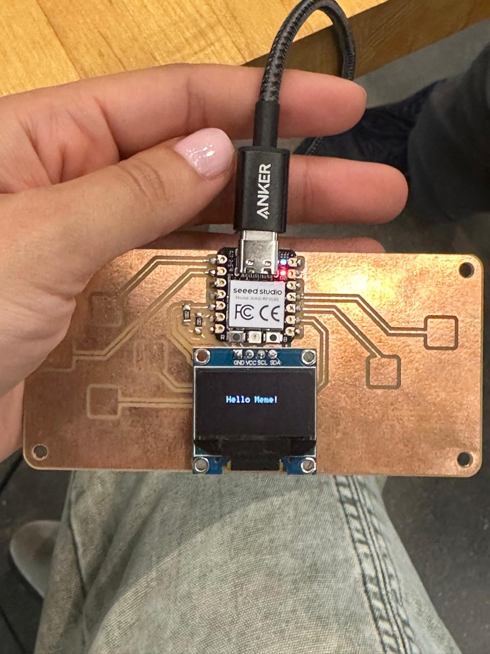
3.2 Display (SSD1306 over I²C)
#include <Wire.h>
#include <Adafruit_GFX.h>
#include <Adafruit_SSD1306.h>

#define SCREEN_WIDTH 128
#define SCREEN_HEIGHT 64
#define SCREEN_ADDRESS 0x3C  // sometimes 0x3D

Adafruit_SSD1306 display(SCREEN_WIDTH, SCREEN_HEIGHT, &Wire, -1, 1700000UL, 1700000UL);

void setup() {
  Serial.begin(0);           // RP2040 USB CDC (auto)
  delay(50);                 // let the screen power up
  display.begin(SSD1306_SWITCHCAPVCC, SCREEN_ADDRESS);
  display.clearDisplay();
  display.display();
  display.setTextSize(1);
  display.setTextColor(SSD1306_WHITE);
}

void loop() {
  display.clearDisplay();
  display.setCursor(28, 25);
  display.print("Hello world!");
  display.display();
}
Wiring used: SDA→D4, SCL→D5, VCC→3V3, GND→GND. If you see "Hello world!" the I²C bus and OLED are good.
3.3 Touch (capacitive pads + LED example)
#define PIN_RED   17
#define PIN_GREEN 16
#define PIN_BLUE  25

#define N_TOUCH   6
#define THRESHOLD 30

int  touch_pins[N_TOUCH]       = {3, 4, 2, 27, 1, 26};
int  touch_values[N_TOUCH]     = {0, 0, 0, 0, 0, 0};
bool pin_touched_now[N_TOUCH]  = {0};
bool pin_touched_past[N_TOUCH] = {0};

void update_touch() {
  int t, t_max = 200, p;
  for (int i = 0; i < N_TOUCH; i++) {
    p = touch_pins[i];
    pinMode(p, OUTPUT); digitalWriteFast(p, LOW);
    delayMicroseconds(25);
    noInterrupts();
    pinMode(p, INPUT_PULLUP);
    t = 0;
    while (!digitalReadFast(p) && t < t_max) { t++; }
    touch_values[i] = t;
    interrupts();
    pin_touched_past[i] = pin_touched_now[i];
    pin_touched_now[i]  = touch_values[i] > THRESHOLD;
  }
}

void print_touch() {
  char buf[30];
  for (int i=0; i < N_TOUCH; i++) {
    sprintf(buf, "%4d ", touch_values[i]);
    Serial.print(buf);
  }
  Serial.println("");
}

void setup() {
  Serial.begin(0);  // RP2040 USB CDC
  pinMode(PIN_RED, OUTPUT); pinMode(PIN_GREEN, OUTPUT); pinMode(PIN_BLUE, OUTPUT);
  digitalWrite(PIN_RED, HIGH); digitalWrite(PIN_GREEN, HIGH); digitalWrite(PIN_BLUE, HIGH); // HIGH = off with this wiring
}

void loop() {
  update_touch();

  // example: button 0 press/release toggles GREEN LED
  if (pin_touched_now[0] && !pin_touched_past[0]) { digitalWrite(PIN_GREEN, LOW);  } // on
  if (!pin_touched_now[0] && pin_touched_past[0]) { digitalWrite(PIN_GREEN, HIGH); } // off

  print_touch();
  delay(50);
}
On touch, numbers jump in Serial Monitor. This proves the capacitive pads + GPIO are behaving.
Source sketches and more examples:
Quentin Bolsee — qpad-xiao / Arduino
.
Note: Serial.begin(0) is valid on RP2040's USB CDC (auto-baud). On other boards you usually use 115200.
4) Re-solder (robust) — the mistake that taught me fast
I powered the PCB while it rested on metal → OLED went blank. I swapped in a fresh XIAO and re-soldered carefully. Lesson: protect the back of the board, use a non-conductive mat, and sanity-test after rework.
5) My own testing phase (post re-solder)
With the fresh XIAO RP2040 soldered in, I began verifying that everything worked. I started with Quentin's base sketches to confirm the board was alive, then modified them myself. These tests show inputs, outputs, and communication all working.
5.1 Heartbeat → "tick" → "hello"
I combined Serial and LED in a heartbeat sketch. Originally it printed "tick" each second — I edited it to say "hello." This was my first authored modification to someone else's code.
// Heartbeat serial
static unsigned long t0 = millis();
if (millis() - t0 > 1000) {
  t0 = millis();
  Serial.println("hello"); // my edit
}Microcontroller & Board (what I'm actually programming)
A microcontroller is a tiny computer that runs one focused program. The sketch has two parts:
setup() runs once, and loop() runs forever. The loop is basically
read → decide → act.
void setup() {  // runs once at power-up
  // pinMode(...), Serial.begin(...), etc.
}
void loop() {   // runs forever
  // read → map → output
}
Microcontroller (chip): RP2040
- Dual-core Arm Cortex-M0+ up to 133 MHz; 264 KB SRAM; external flash
- USB device, GPIO (digital / PWM / analog), timers, I²C / SPI / UART
- Logic level: 3.3 V (not 5 V tolerant)
Board (module): Seeed Studio XIAO RP2040
- USB-C (power + programming), 3.3 V regulator, boot/reset (UF2), user LED
- Castellated pins break out the RP2040's GPIO so I can solder/use them
My understanding is: the RP2040 is the engine; the XIAO board is the car around it (USB, power, pins).
Why both matter: the datasheet tells me what the chip can do; the board docs tell me how those pins are wired so I can actually use them.
Summary: I am programming the RP2040 microcontroller via the XIAO RP2040 board on my PCB.
Arduino Programming Cheat Card (XIAO RP2040)
void setup() { /* runs once at startup */ }
void loop()  { /* runs forever */ }

// Pins
pinMode(pin, OUTPUT);
pinMode(pin, INPUT_PULLUP);
digitalWrite(pin, HIGH);   // on
digitalWrite(pin, LOW);    // off
int d = digitalRead(pin);  // HIGH/LOW

// Analog & Serial
int a = analogRead(A0);    // 0..1023
Serial.begin(115200);
Serial.println("Hello");

// Timing
delay(500);                 // 500 ms = 0.5 s
unsigned long t = millis(); // ms since boot
Troubleshooting (what actually happened)
- Serial gibberish → baud mismatch: set
115200. - Blank OLED → check I²C wiring (SDA=D4, SCL=D5), try
0x3Cvs0x3D, power cycle. - Touch flatline → wrong pins in
TOUCH_PINSor a dry joint; reflow with flux. - After soldering → clean flux, continuity test, re-run "blink + hello" before complex code.
How this meets the assignment
- Datasheet: I read the RP2040 + XIAO docs (see Sources) and summarized chip vs board, voltage limits, and I²C pins.
- Program & interaction: I authored an Arduino sketch that reads local inputs (touch pads) and drives local outputs (OLED drawing, LED).
- Communication: I used USB Serial for the heartbeat "tick → hello" and raw touch prints. I also used a Processing sketch on my laptop as a remote visualization (serial → animation). [I'll add screenshots here]
- Extra credit (envs/languages): Primary in Arduino (C/C++). I experimented with Processing (host-side visualization toolchain). Next I may try CircuitPython to compare workflows.
Group Assignment — Toolchains & Workflows (Reference)
For group assignment we were asked to compare embedded architectures and development workflows (Arduino C/C++, MicroPython/CircuitPython, toolchains, and bootloaders). See our group page and a classmate's write-up for details:
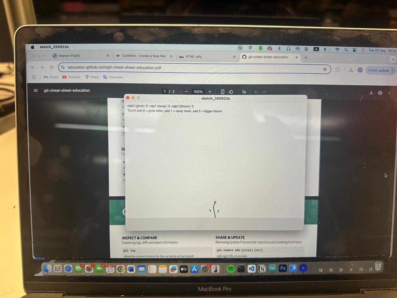
My program — touch-controlled plant on the OLED
I wanted something a bit poetic: a plant that "grows" and "sways" when I touch the pads.
Touch values are normalized to 0..1 and mapped to parameters (stem height, sway angle, bloom size).
OLED is SSD1306 128×64 over I²C: SDA → D4, SCL → D5, VCC → 3V3, GND → GND.
Update TOUCH_PINS to match your board.
#include <Wire.h>
#include <Adafruit_GFX.h>
#include <Adafruit_SSD1306.h>

#define SCREEN_WIDTH 128
#define SCREEN_HEIGHT 64
#define OLED_RESET   -1
#define I2C_ADDR     0x3C

Adafruit_SSD1306 display(SCREEN_WIDTH, SCREEN_HEIGHT, &Wire, OLED_RESET);

// === Update to YOUR touch pad pins ===
const int TOUCH_PINS[] = {2, 3, 4};
const int N = sizeof(TOUCH_PINS)/sizeof(TOUCH_PINS[0]);

uint32_t tMin[3] = {100000,100000,100000}, tMax[3] = {0,0,0};

// crude capacitive read: higher when touched
uint32_t readCapRaw(int pin, int samples=6){
  uint32_t total=0;
  for(int s=0; s<samples; s++){
    pinMode(pin, OUTPUT); digitalWrite(pin, LOW); delayMicroseconds(5);
    pinMode(pin, INPUT_PULLUP);
    uint32_t t0 = micros();
    while(digitalRead(pin)==LOW){ if(micros()-t0 > 3000) break; }
    total += (micros()-t0);
  }
  return total / samples;
}
float clamp01(float v){ return v<0?0:v>1?1:v; }
float norm(float v, float lo, float hi){ return (hi<=lo+1)?0.0f: (v-lo)/(hi-lo); }

void setup(){
  pinMode(LED_BUILTIN, OUTPUT);
  Wire.begin();
  if(!display.begin(SSD1306_SWITCHCAPVCC, I2C_ADDR)){
    while(true){ digitalWrite(LED_BUILTIN, !digitalRead(LED_BUILTIN)); delay(100); }
  }
  display.clearDisplay(); display.setTextSize(1); display.setTextColor(SSD1306_WHITE);
  display.setCursor(0,0);
  display.println("Touch plant: D4/D5=I2C");
  display.println("Pad0=grow 1=sway 2=bloom");
  display.display();
  delay(600);
}

void loop(){
  uint32_t cap[3] = {0,0,0};
  for(int i=0; i<N && i<3; i++){
    cap[i] = readCapRaw(TOUCH_PINS[i], 10);
    if(cap[i] < tMin[i]) tMin[i] = cap[i];
    if(cap[i] > tMax[i]) tMax[i] = cap[i];
  }

  float n0 = (N>0) ? clamp01(norm(cap[0], tMin[0], tMax[0])) : 0.0f; // height
  float n1 = (N>1) ? clamp01(norm(cap[1], tMin[1], tMax[1])) : 0.5f; // sway
  float n2 = (N>2) ? clamp01(norm(cap[2], tMin[2], tMax[2])) : 0.3f; // bloom

  int   stemLen = (int)(20 + n0 * 42);
  float sway    = (n1 - 0.5f) * 0.8f;
  int   bloomR  = (int)(3 + n2 * 10);

  display.clearDisplay();

  int baseX=64, baseY=62;
  display.drawLine(0, baseY, 127, baseY, SSD1306_WHITE);

  int x0=baseX, y0=baseY;
  int x1=baseX, y1=baseY - stemLen/3;
  int x2=baseX + (int)(sway*18), y2=baseY - (2*stemLen)/3;
  int x3=baseX, y3=baseY - stemLen;

  display.drawLine(x0,y0, x1,y1, SSD1306_WHITE);
  display.drawLine(x1,y1, x2,y2, SSD1306_WHITE);
  display.drawLine(x2,y2, x3,y3, SSD1306_WHITE);

  auto leaf=[&](int x,int y,float ang,int len){
    int x2=x+(int)(cos(ang)*len), y2=y+(int)(sin(ang)*len);
    display.drawLine(x,y,x2,y2,SSD1306_WHITE);
    display.drawLine(x,y,x2,y2+3,SSD1306_WHITE);
    display.drawLine(x2,y2,x2,y2+3,SSD1306_WHITE);
  };
  leaf(baseX-8, baseY - stemLen*2/5, -1.9f + sway*0.6f, 10 + (int)(n0*8));
  leaf(baseX+8, baseY - stemLen*3/5,  1.9f + sway*0.6f, 10 + (int)(n0*8));

  display.drawCircle(x3, y3, bloomR, SSD1306_WHITE);
  display.fillCircle(x3, y3, bloomR/2, SSD1306_WHITE);

  display.setTextSize(1); display.setCursor(0,0);
  display.print("c0:"); display.print(cap[0]);
  display.print(" c1:"); display.print(cap[1]);
  display.print(" c2:"); display.print(cap[2]);
  display.display();

  delay(30);
}
Sources
- In-class & recitations; electronics presentation by Anthony.
- Quentin Bolsee — XIAO RP2040 sanity tests (touch/LED), notes & code references.
- Seeed Studio XIAO RP2040 docs (pinout, I²C), RP2040 datasheet.
- Group reference: EECS Week 03 page
- Group section: Saleem's week 2
- ChatGPT (GPT-5 Thinking) — tutoring and code scaffolding. Verified on my hardware and adapted to my PCB.