03.25 Update
- Rough assembly of TinyZ (with available parts)
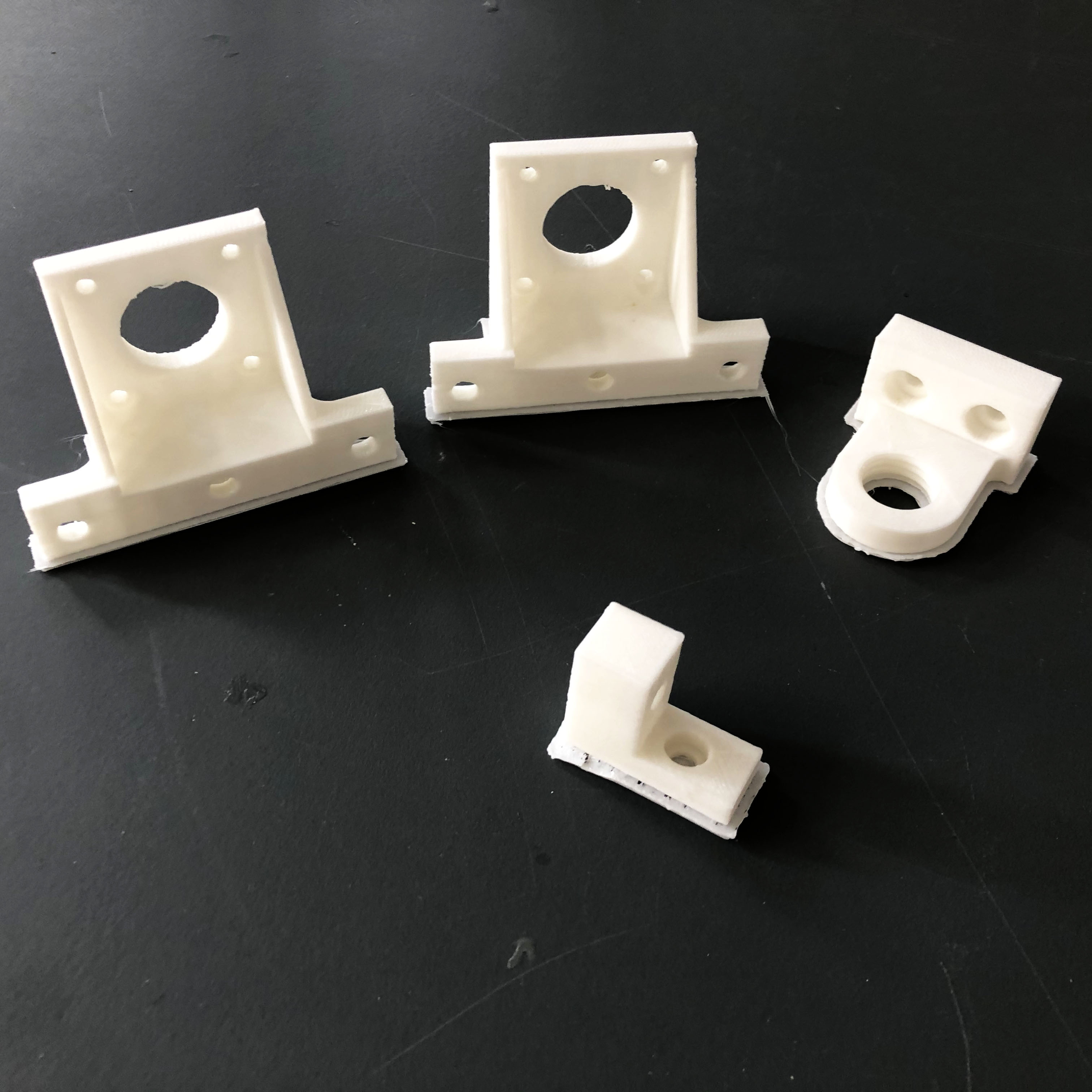
- Fabrication of customized parts (3D prints, waterjet)
- First pass on the print-head end-effector
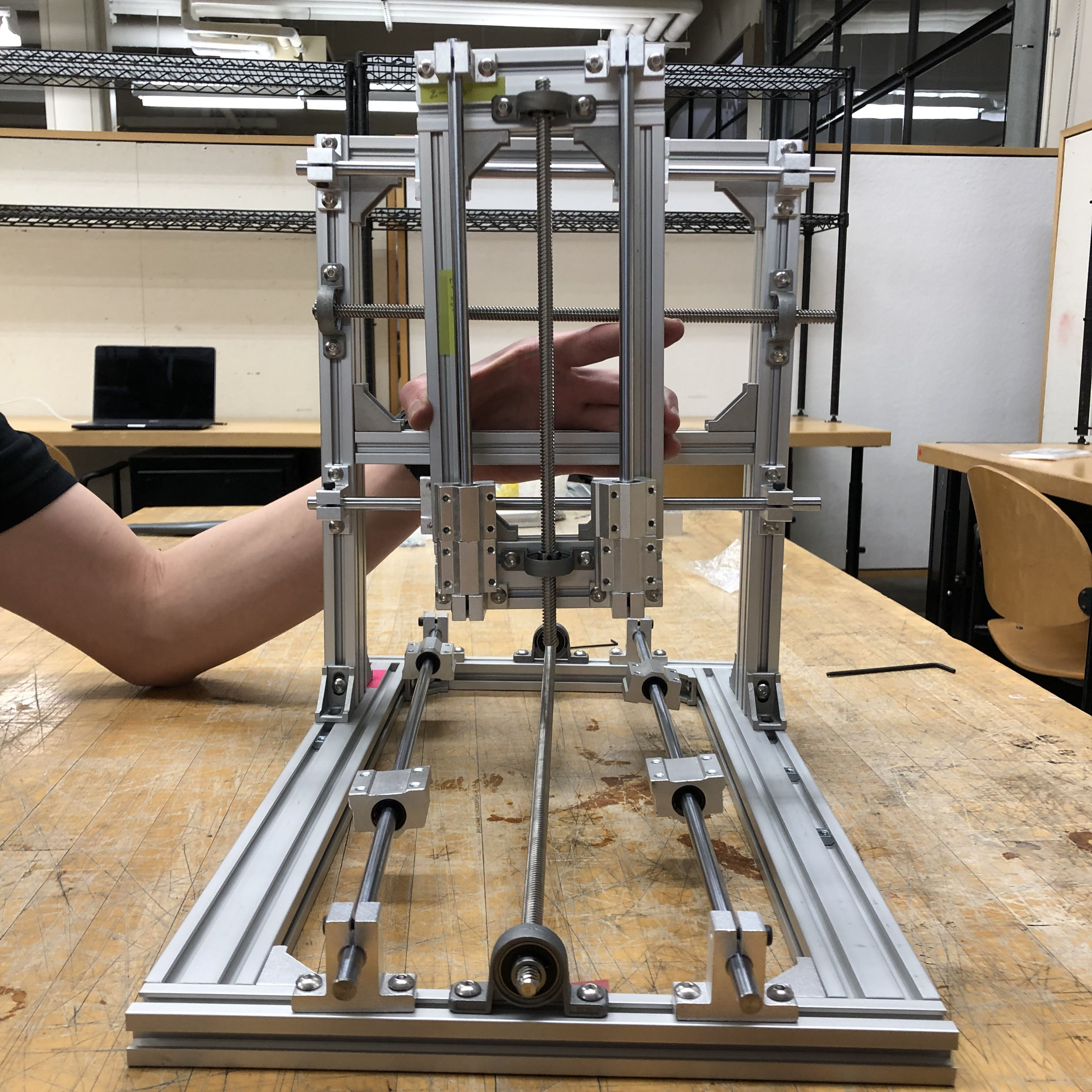
TinyZ Assembly + Prep
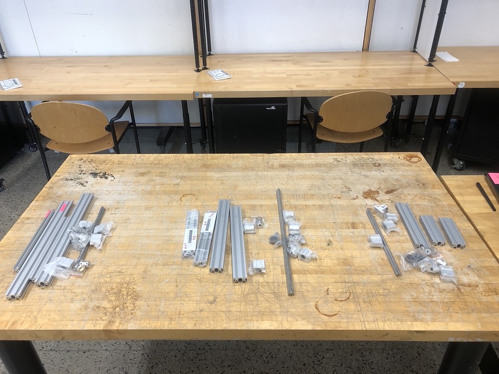
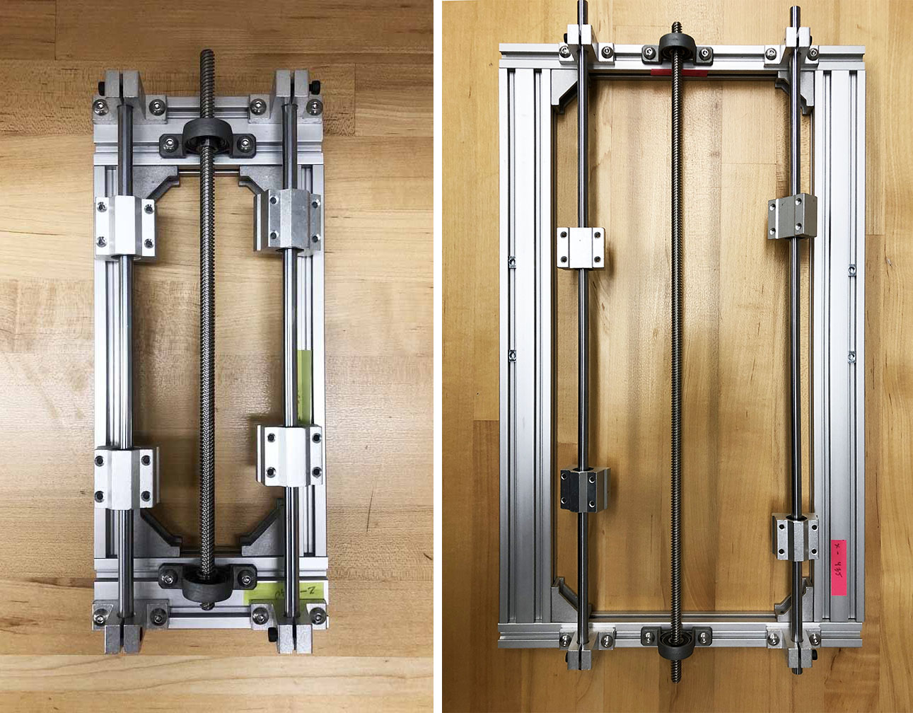
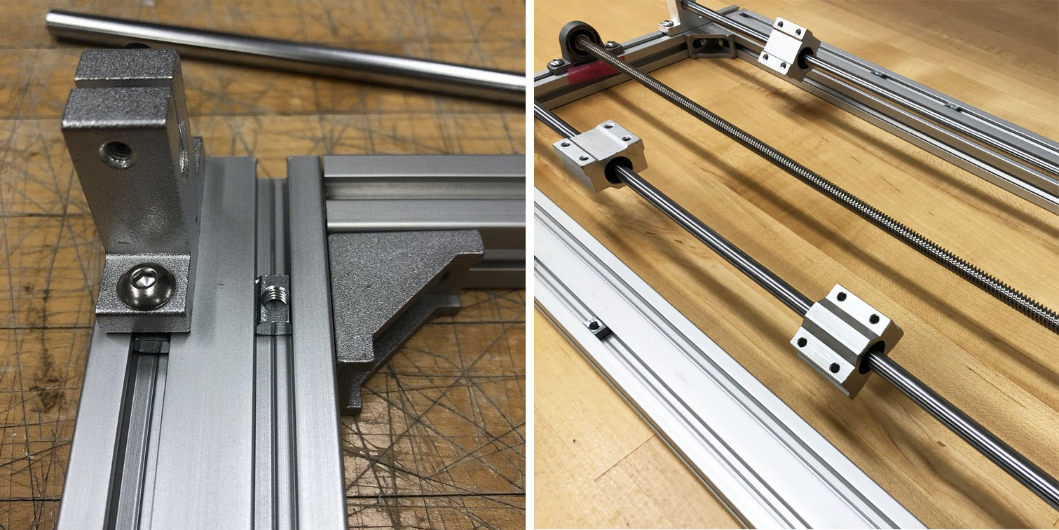
The complete list of parts can be found here. The assembly of each of the axes is pretty similar, with the size of the aluminmum frames being slightly different: x-axis (50cm ) y-axis (30cm) z-axis (30cm). In order to connect the frame profiles we used corner brackets that were secured by 10mm T-Slot Nuts and M5x10mm hex socket screws.
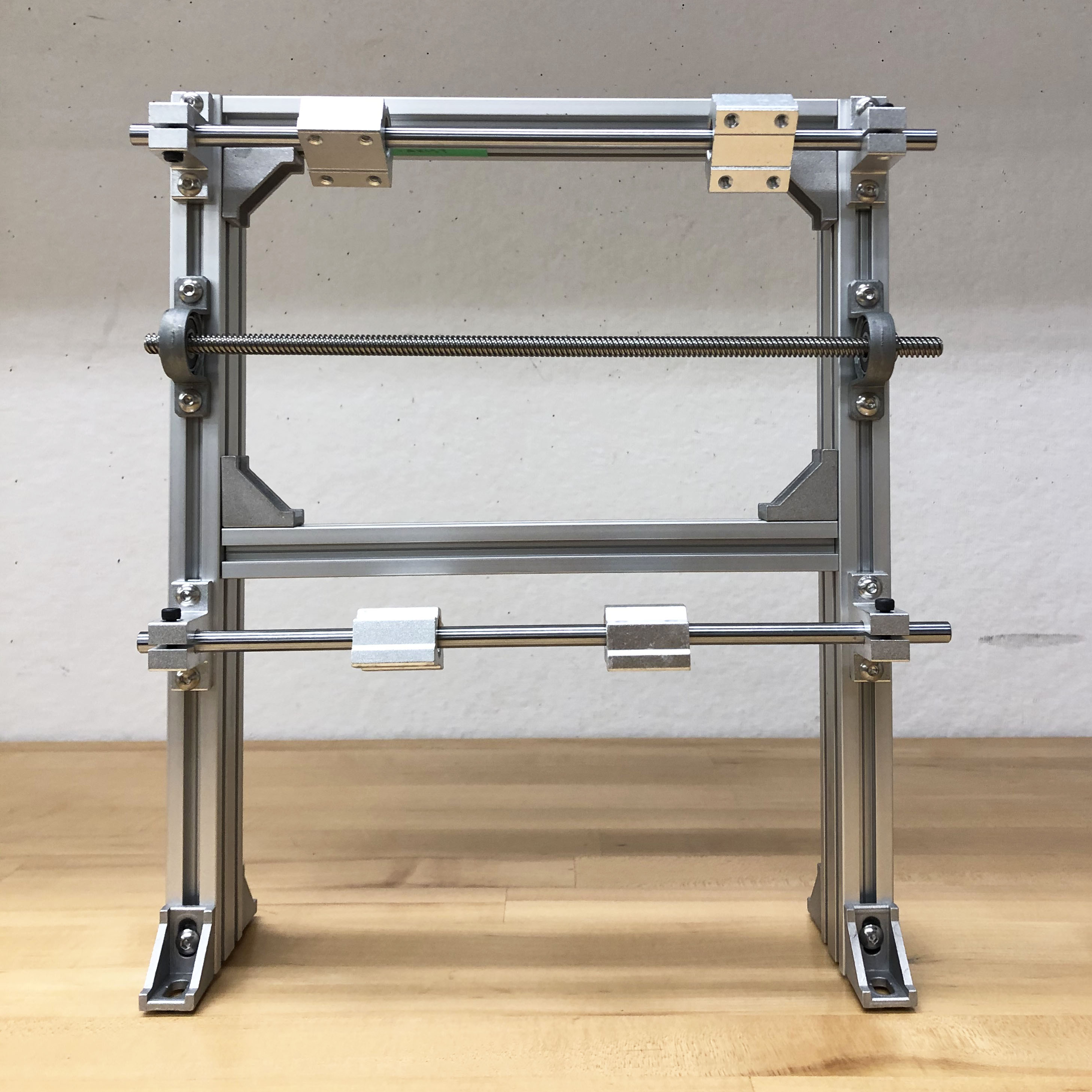
This is a rough assembly of all axes together. We'll be using 3 aluminum plates that are 1/4" thick in order to attach the axes together as well as to ensure the aluminum profiles are spaced evenly and parallel.
We used the Sindoh printer at the studio to print our parts - we followed some of the tutorials provided at archishop and Sindoh and used PLA as that was recommended. The 3D print components will be used for attaching the 3 Nema motors, the dremel, and finally the tinyG controller.
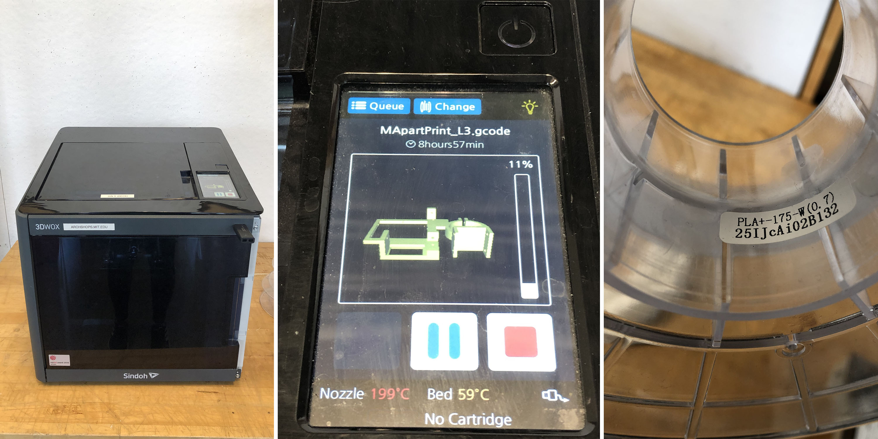
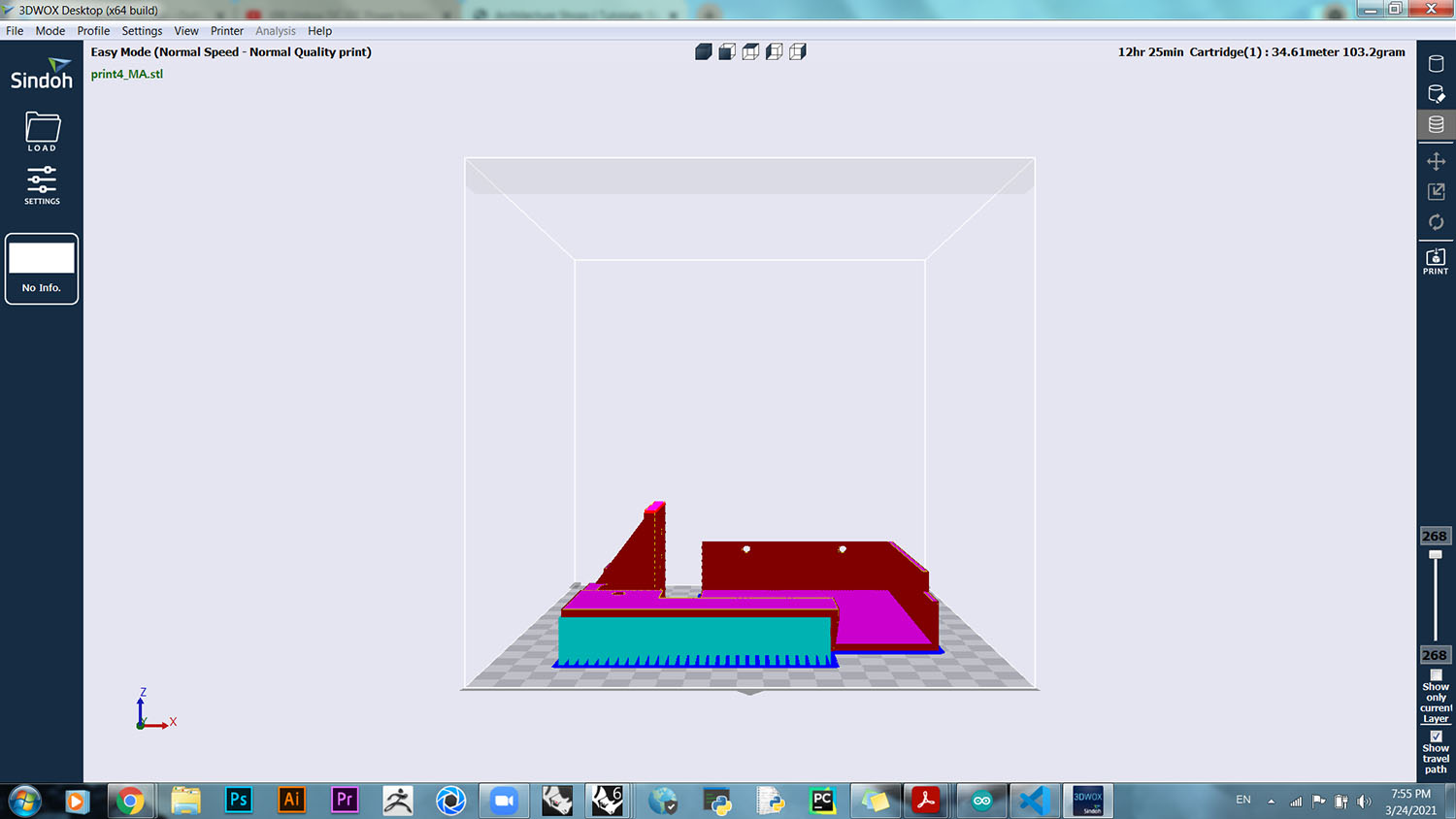
In order to generate the toolpaths and g-code we used 3DWOX - which was pretty straightforward and easy to use. The prints took quite a while to finish, about 5-10 hours per file. We had the setting as normal speed although the some of the prints turned a little rough.
DTS Print Head
- HP6602 Print Head by Norbert Heinz
- World Printer by Norbert Heinz
- DIY Inkjet Printer by Dominik Meffert
- Ink Shield by Nicholas Lewis
- DIY Inkjet Printer by Nicholas Lewis + Patrick Hannan + Jared Knutzen + Joy Markham
The Mechanics of Inkjet Printing:
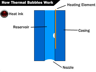
I came across a few resources that explain how inkjets work: To summarize, the inkjet printer is a non-impact printer, meaning it does not touch the paper in order to produce an image; it uses a series of nozzles to spray drops of ink. There seems to be two different methods of releasing the droplets - if I'm not mistaken, our print-head uses the Thermal Bubble method; the resistors within the inkjet printer produce heat after receiving an electric pulse, the heat then vaporizes the ink to create a bubble. This causes the bubble to expand, pushing the ink out of the nozzle. A vacuum is created once the bubble pops, pushing more ink out of the nozzle.
We used this circuit diagram, produced by Norbert Heinz for the HP6602 Print Head as a reference when building our own circuit; although without the raspberry Pis and motors.
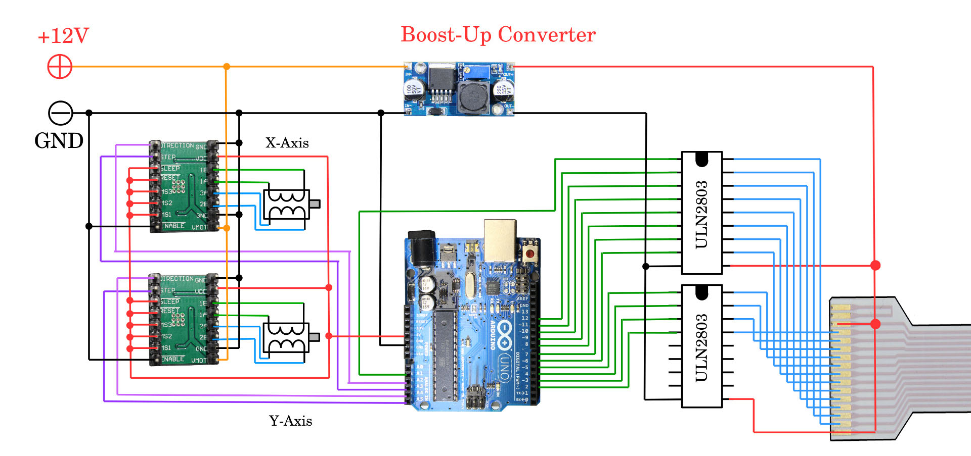
- Arduino Uno
- HP6602A printhead + printhead mount
- ULN2803 Transistor
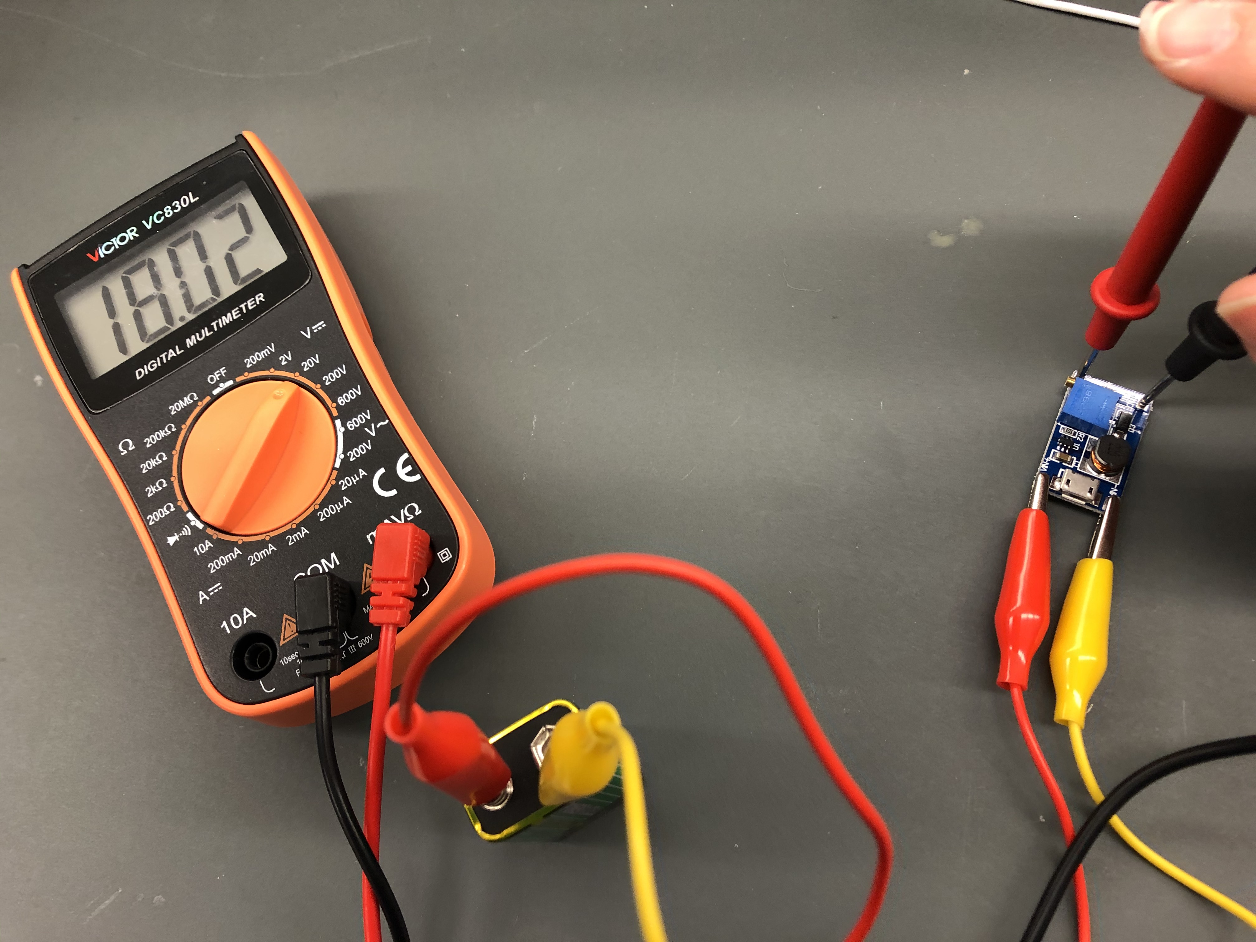
- Step-Up DC/DC Adjustable Converter
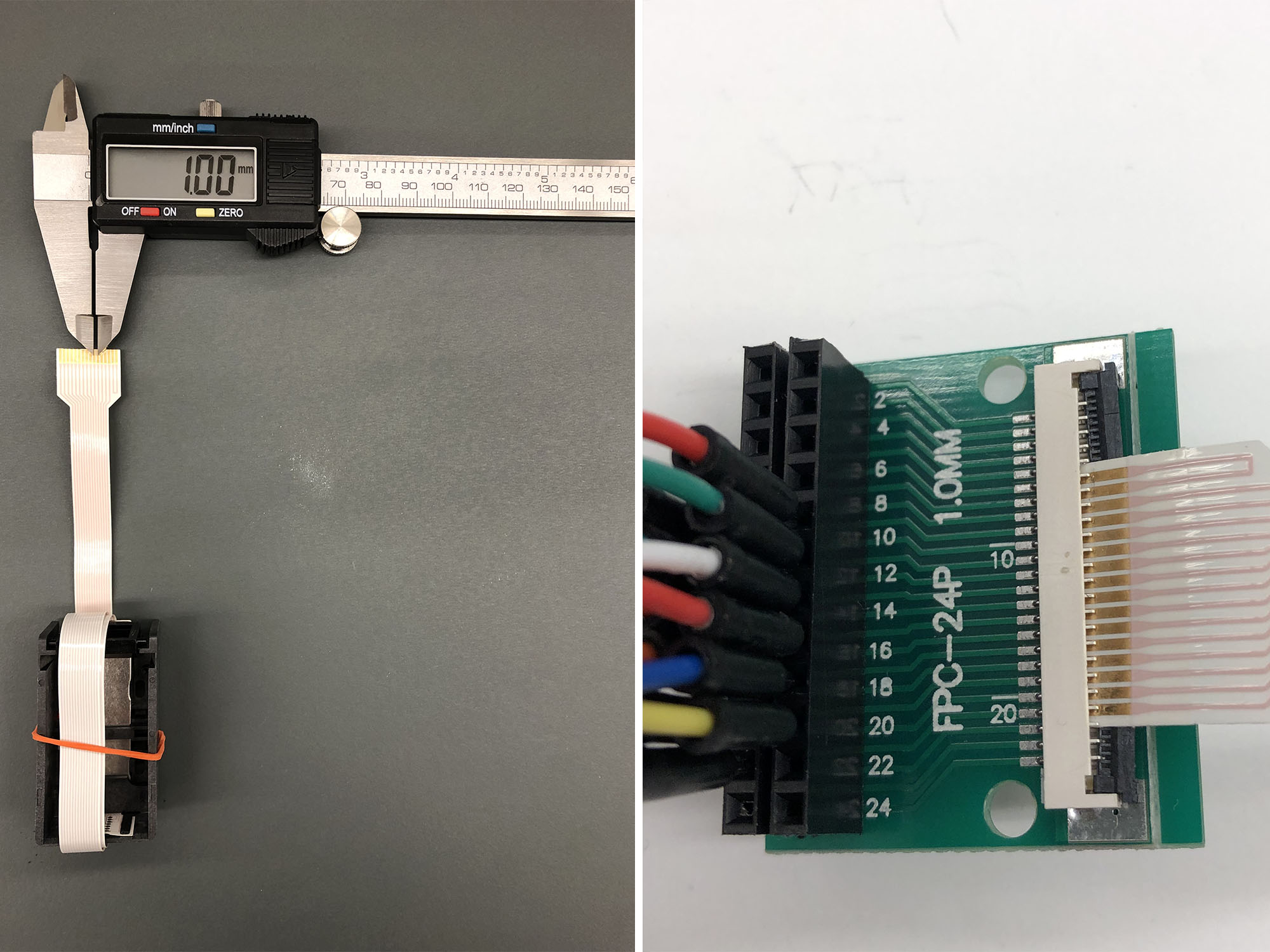
- Flexible Printed Circuit Connector (FPC) - 1.0mm pitch
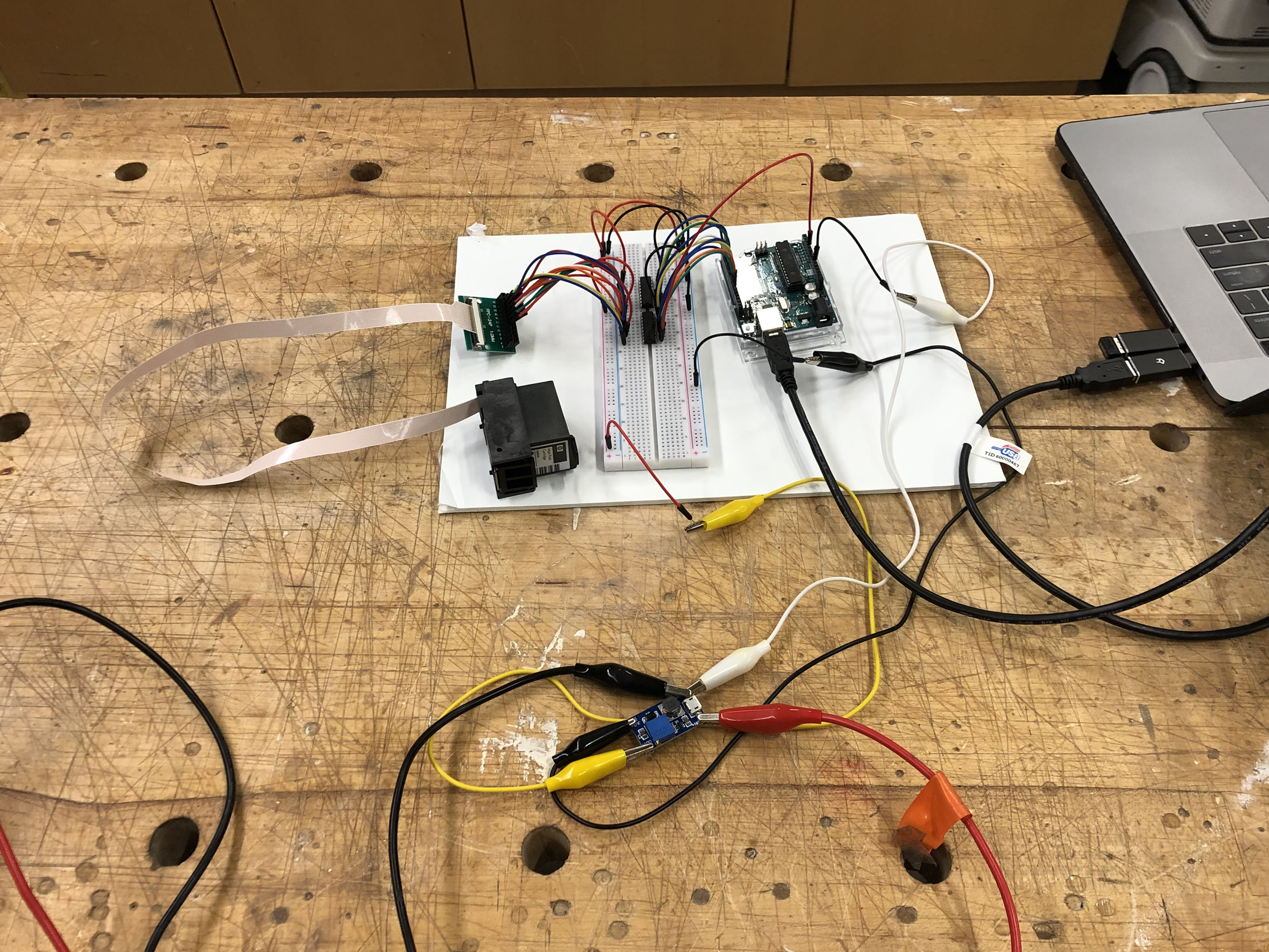
We used a 9V battery source that was connected to the step-up converted, we adjusted it accordinly until the multi-meter read 18V.
Although it seems we used the correct FPC connector since we measured the distance between each copper strip center and it is 1.0mm. We ran into an issue when checking for short circuits using the multi-meter. The pins towards the edge were problematic as opposed to those that were in the center. The videos show the multi-meter tests that were ran. We're not sure how to debug this issue, the cable connector was soldered on so perhaps that is effecting the continuity test.
We've ordered this new FPC connector to test out, but this is how far we've gotten to this week. Unfortunately, we weren't able to get inkjet to spray ink just yet.