03.18 Update
This week, while we are waiting for our parts to come in I was looking into further warm-up exercises as follows:
- Further exercises with Arduino + Motors
- Electronic Design + Production
- Embedded Programming
Servo-Motor Exercise
I've been following along Paul McWhorter fantastic playlist of Arduino Tutorials
In this exercise I'm using Hitec RCD 31422S HS-422 Deluxe Servo
specifically two, to be controlled by the joystick. The goal of this exercise is to control the top servo by motioning the joystick in the x-axis while controlling the bottom servo by motioning the jostick in the y-axis.
Embedded Programming
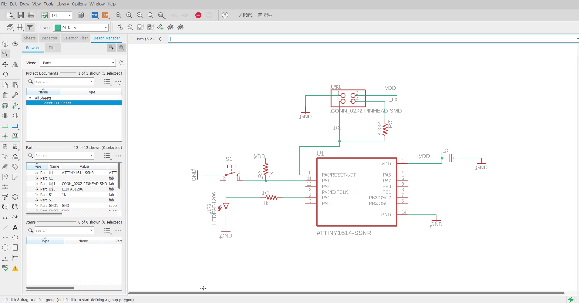
This week I had decided to give Eagle a try - I was following along Anthony's tutorial from last year as well as came across
this webinar which I thought to be very useful.
Before designing my own circuit, I was referncing some of the ATtiny designs that were posted onto CBA website in particular the ATtiny1614 and ATtiny412.
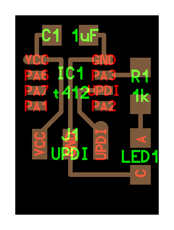
Before designing my own circuit, I was referncing some of the ATtiny designs that were posted onto CBA website in particular the ATtiny1614 and ATtiny412.
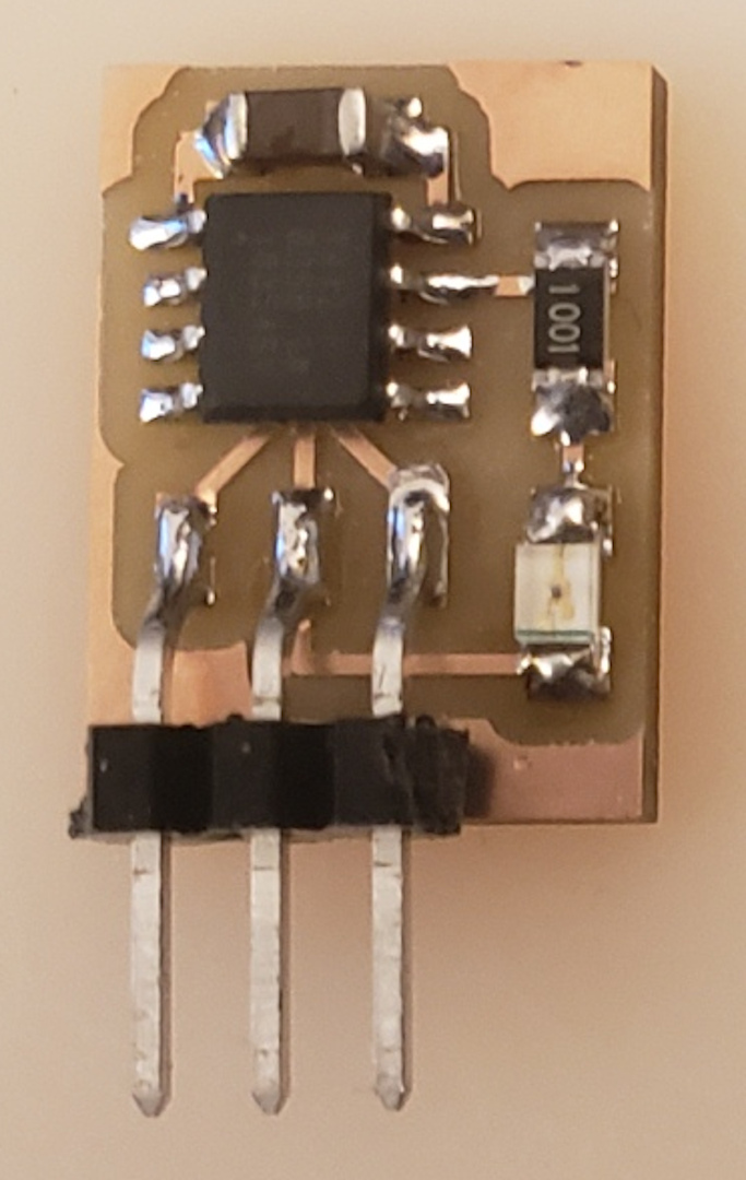
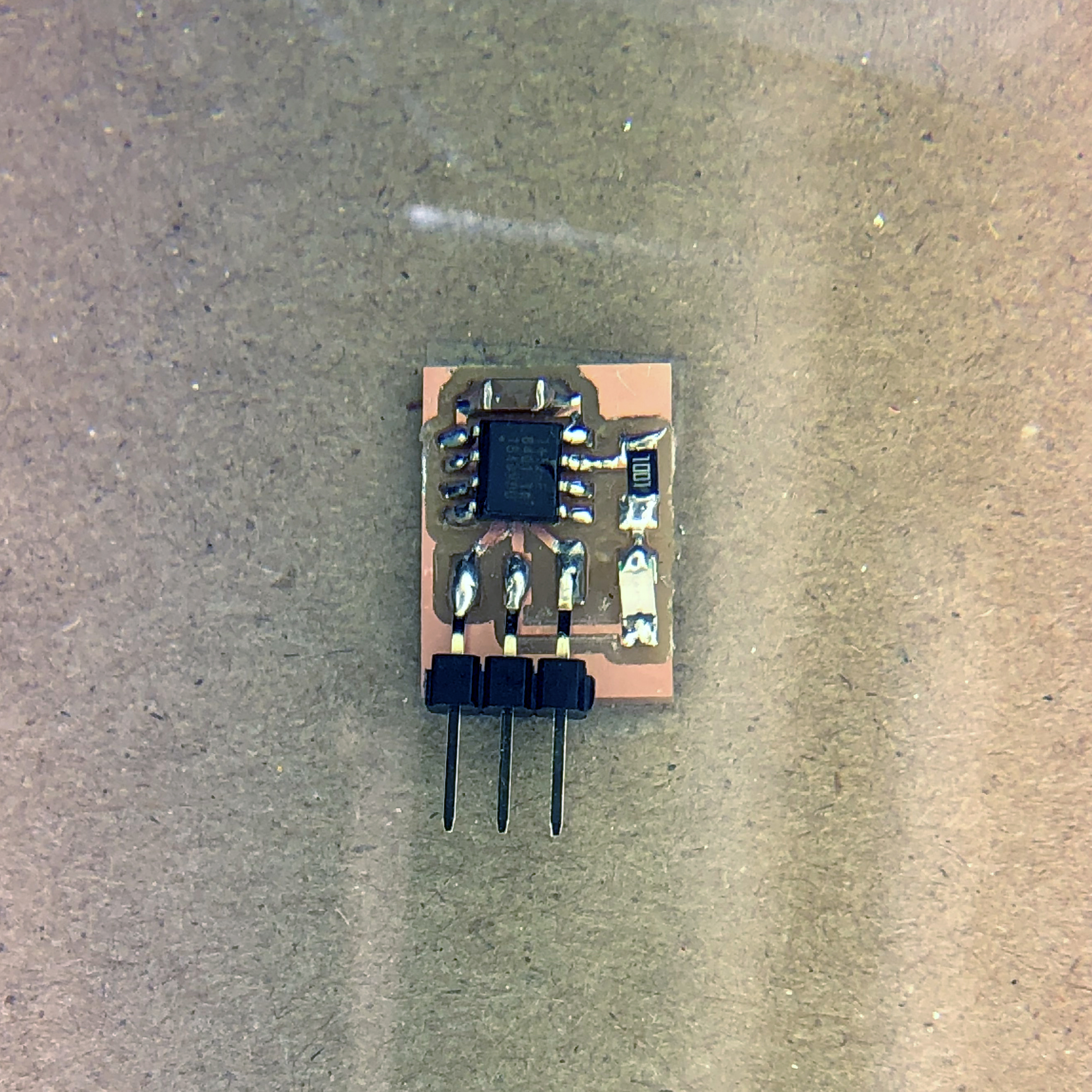
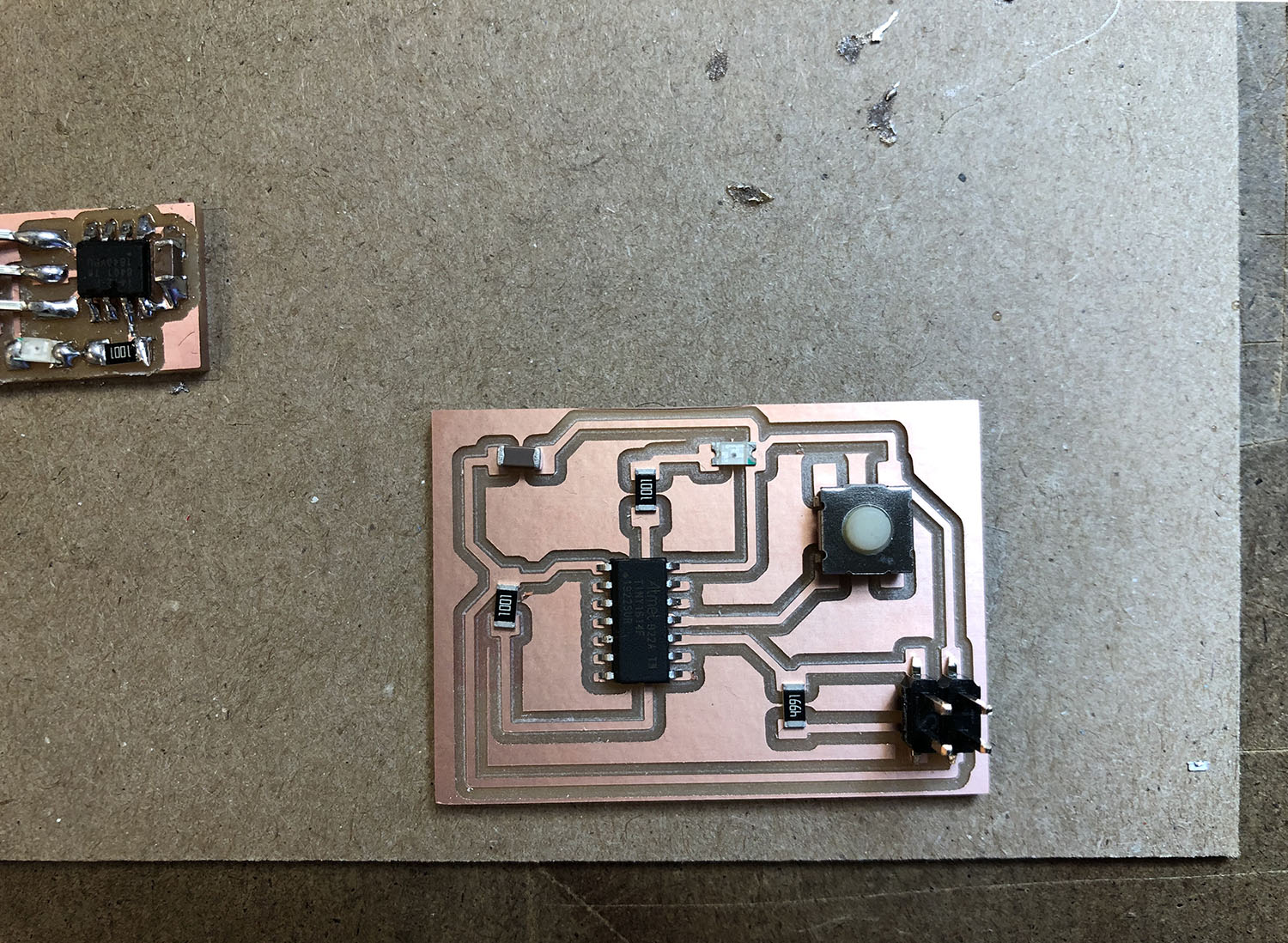
I had decided to reproduce the circuit design above, thought it would be a good exercise of trying to solder the components onto the board.
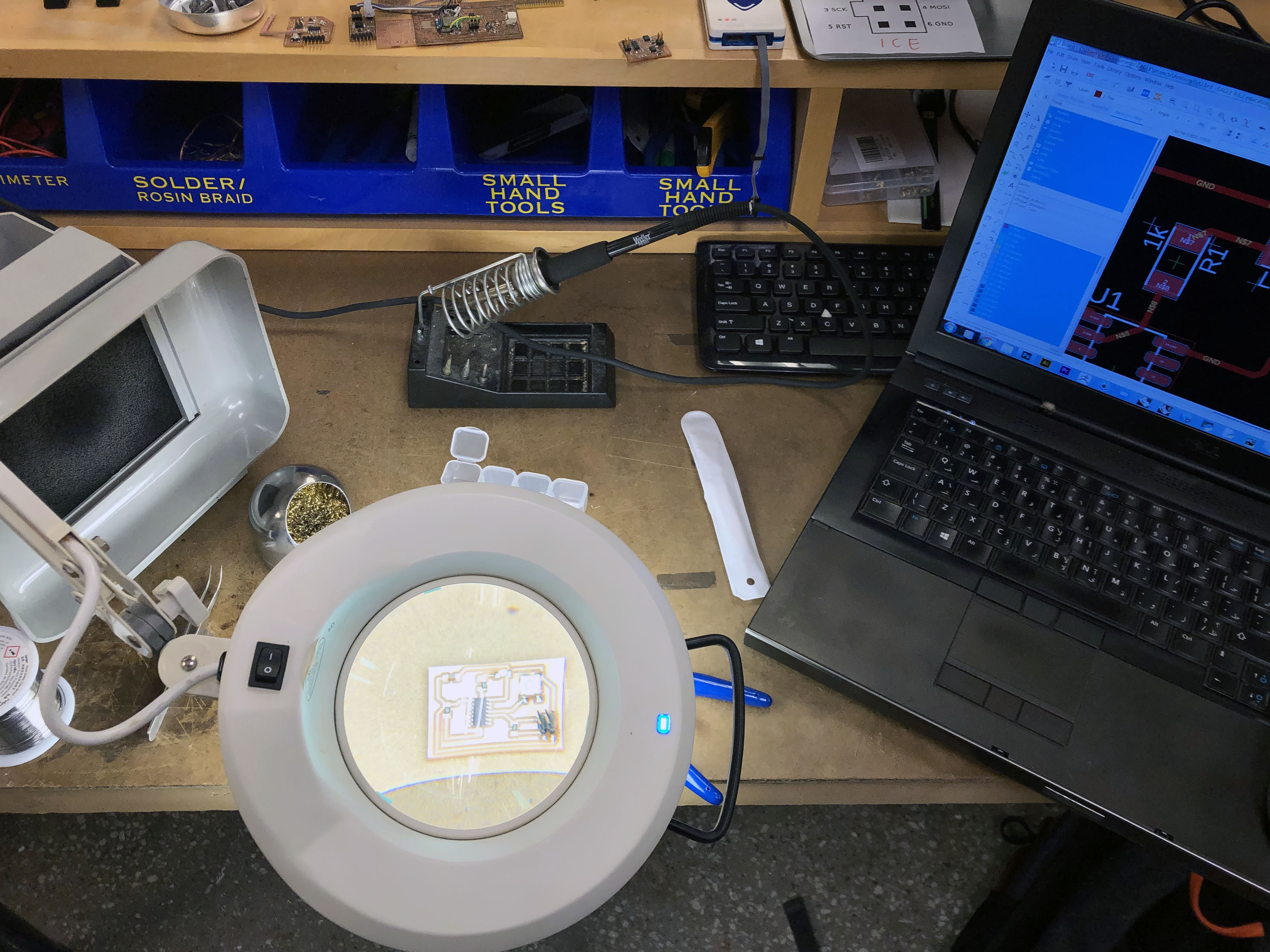
and get a sense of component scale, which were to my suprise very tiny... I struggled quite a bit soldering the components, my hands were very shaky and often times I'd accidentally fuse some parts together and had to de-solder and repeat the process all over again- which made it a very slow process.
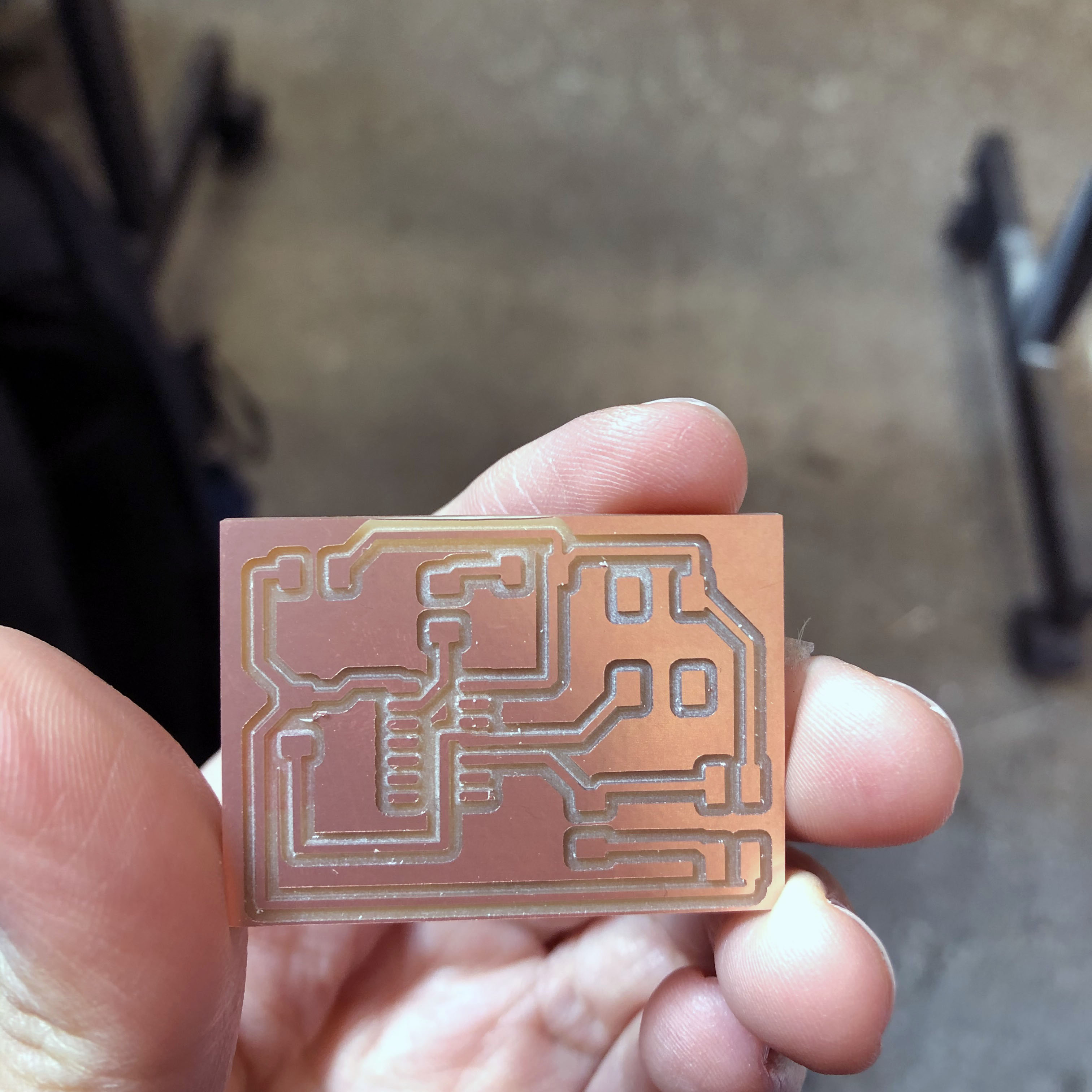
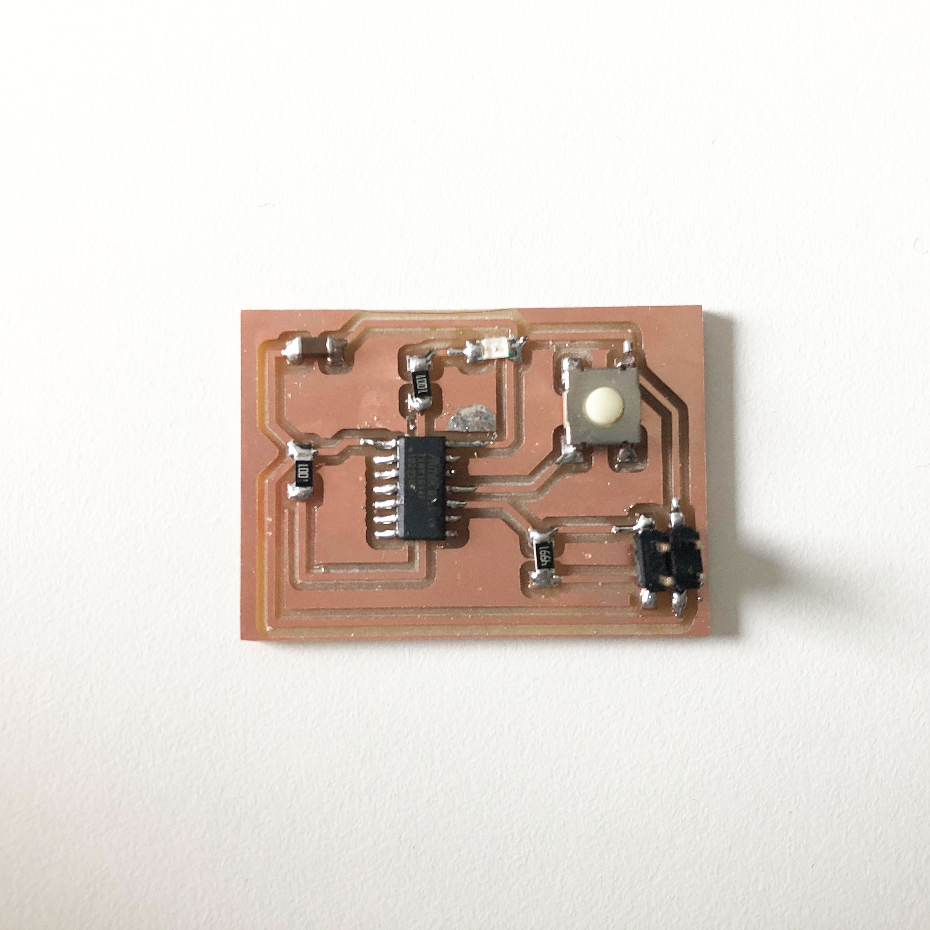
Well, this was the output - not too terrible I guess? Also, just a tip for future reference - before vacuuming away the copper bits, make sure to remove your routed PCB.
I had the unfortunate event of the vaccuum sucking away the pcb and was unable to retreive it, having to mill it again!
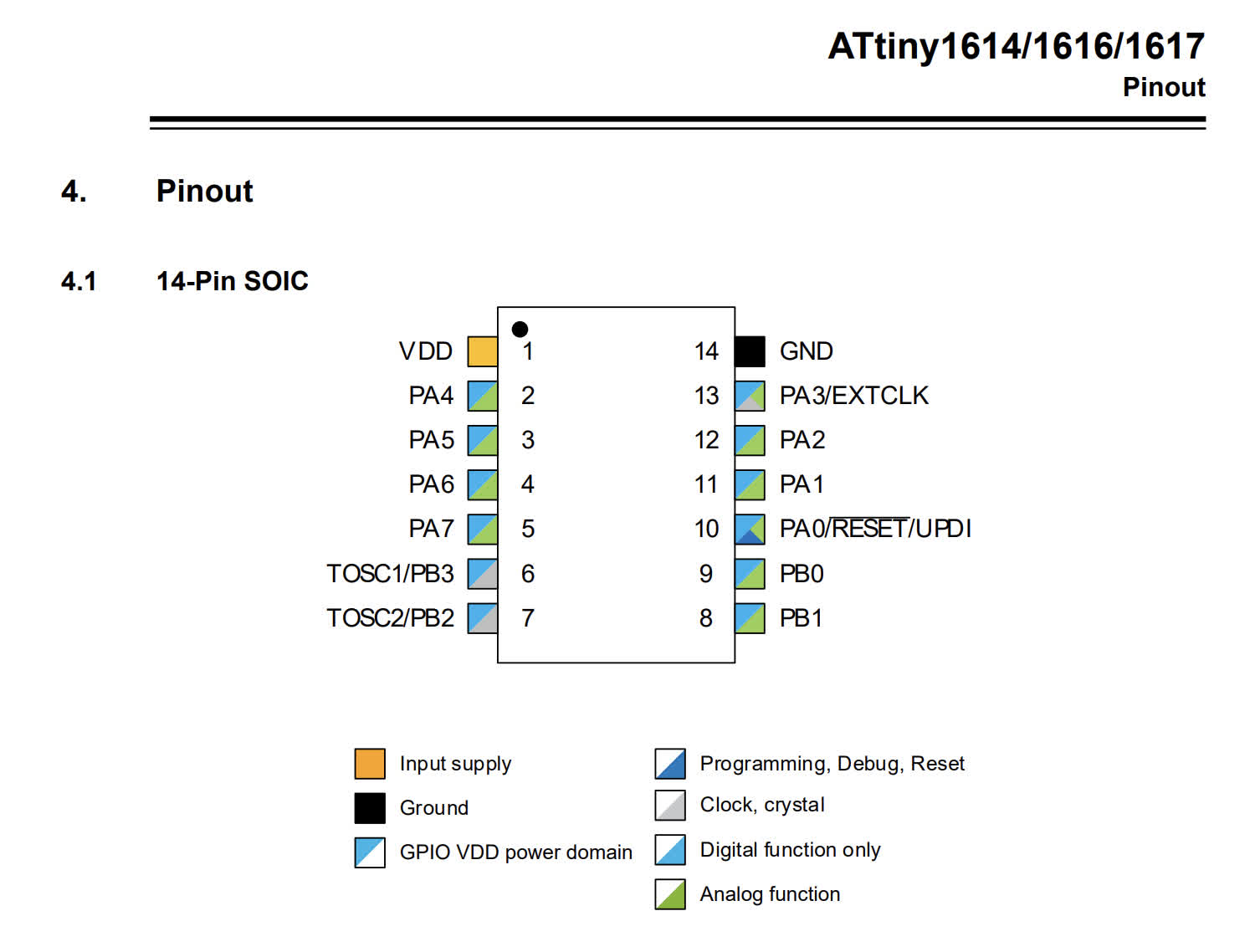
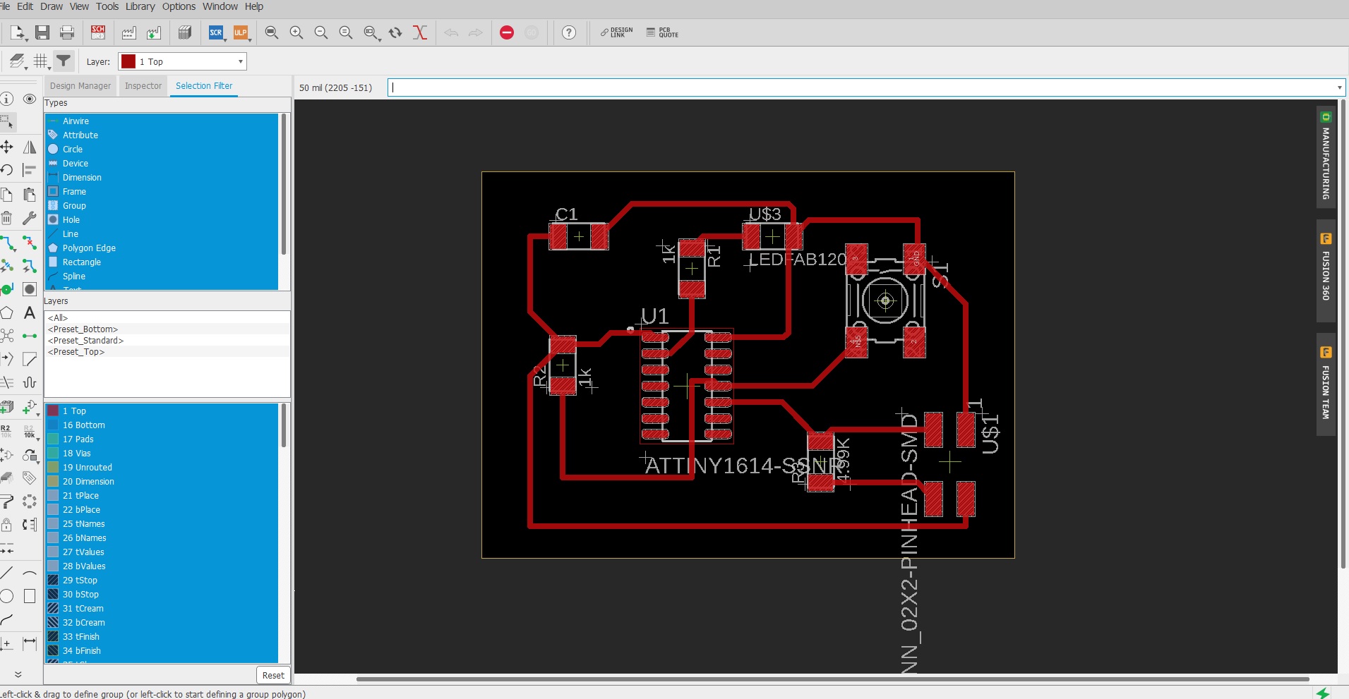
- ATTiny1614-SSNR
- R1 and R2: 1K resistors
- S1: SW262CT-ND
- C1: 1uF
- Red LED
- Conn: 2x2 Pinhead SMD
Next Steps
We heard back from Jake that our parts have arrived, next step would be to assemble TinyZ and get it working by the weekend.
Hopefully by then we'll be able to integrate print-head component
and look into designing the end-effector to have a more seamless integration with the machine setup.