04.08 Update
Inkjet Print Head
This week I came across this fantastic book *which has been discontinued for a while* titled Inkjet Applications by Matt Gilliland. . It has been quite a good resource in further understanding the systems embedded in the print-head and looking at examples of how to hack it.
Below are a few notes from the book that I thought were useful/interesting:
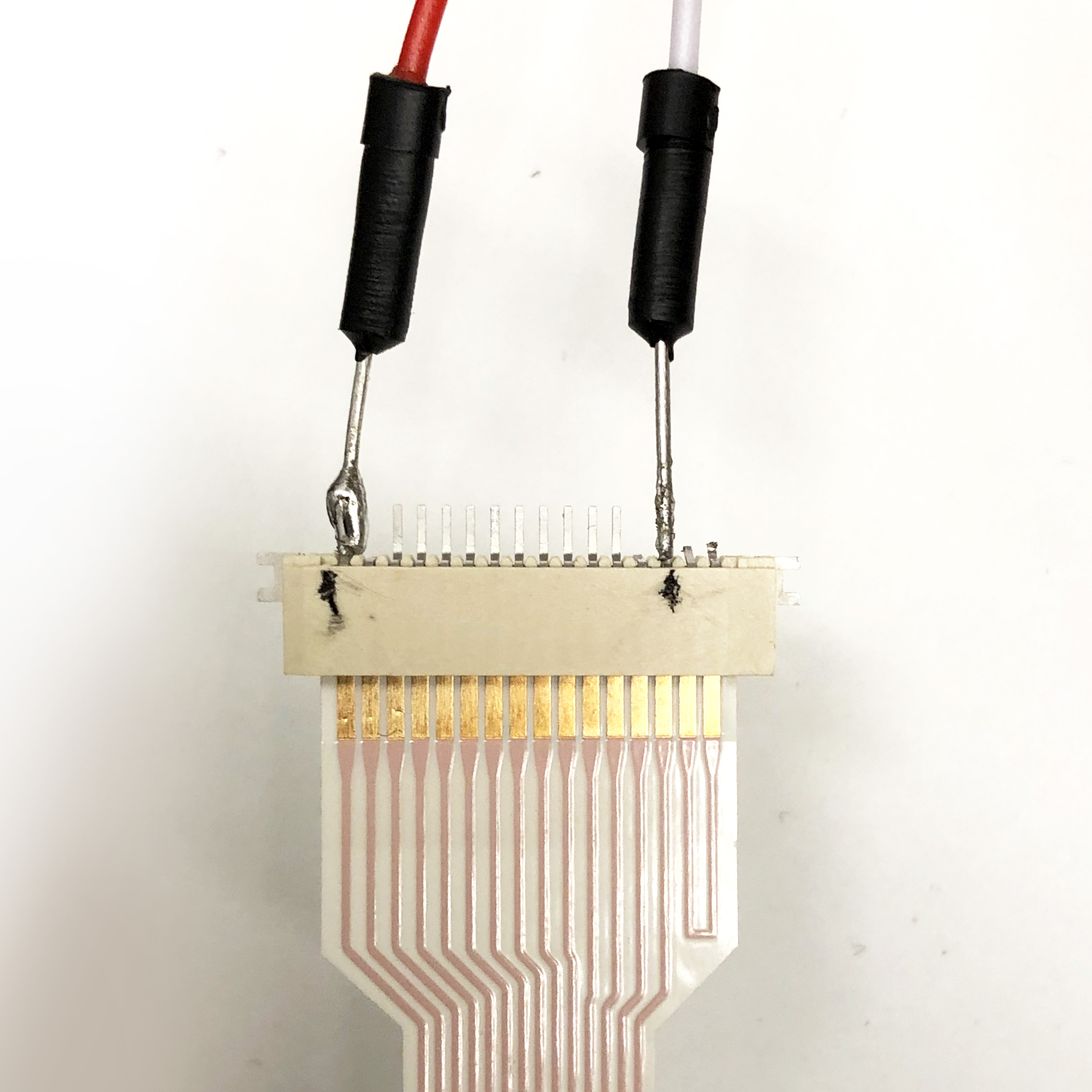
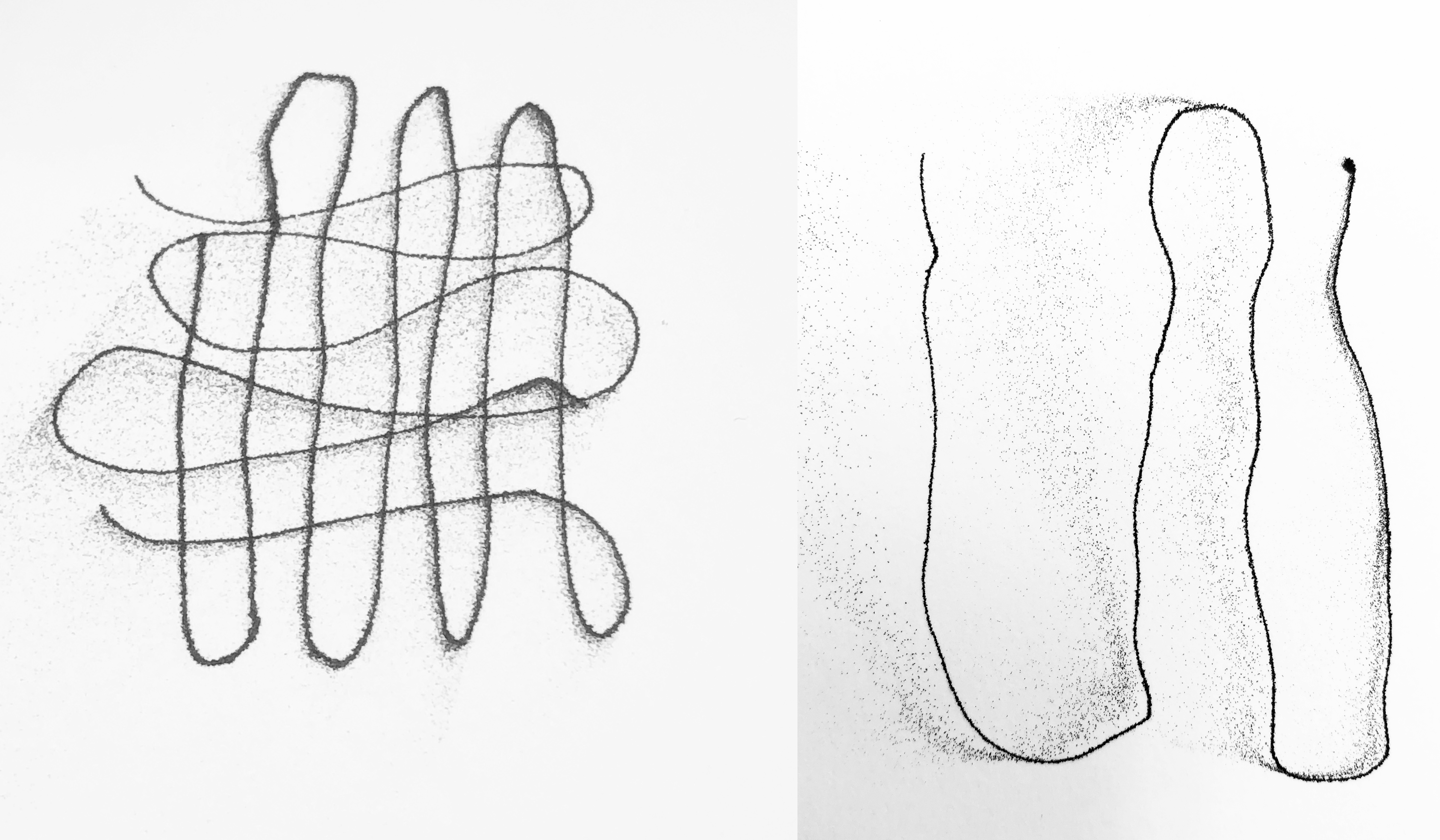
We used a simple Arduino code to send electrical pulses to a single nozzle to squirt ink. After a few trial and errors, it worked! :) We had a little fun with free-hand printing.
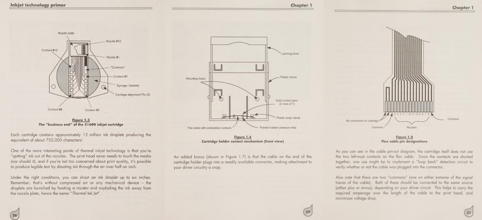
- Each cartridge contains approx 12 million ink droplets which is the equivalent of about 750,000 characters
- The print-head should not touch any media, it's possible to produce legible prints by squirting ink from a distance of 1/2"& under the right conditions the print-head can shoot up to 6"
- The cartridge does not use the two left-most contacts on the flex cable, as they are shorted together - one use is to implement a "loop back" detection circuit to verify whether or not the cable is plugged to the connector
- Each nozzle is completely independent of the others, although a single ink supply feeds all nozzles.
- Since the resistor is heated by current flow - it's important that the voltage pulse and duration is no more than 40 microjoules of energy as to not burn the resistor
- Do not fire more than two droplets at a time. The droplets from the nozzles must also be physically separated from each other. For example, #1 + #7 or #8 + #2
- Wait a total of 800 microseconds before firing the next droplet out of the same nozzle as a minimum for pulse spacing between successive droplets.
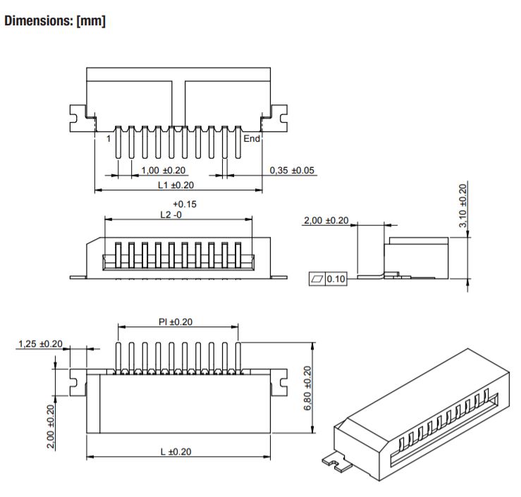
We continued to develop the print-head and have switched our FPC connector to the Würth Elektronik connector - which has a 1.0mm pitch, this time around the print flex cable fit well.
- Control inductive loads - the darlington array act as seperate 8 individual switches that can be turned off and on as desired.
- Drive multiple loads - it is capable of driving 8 loads at a time
We used a simple Arduino code to send electrical pulses to a single nozzle to squirt ink. After a few trial and errors, it worked! :) We had a little fun with free-hand printing.
TinyZ Motor Tests
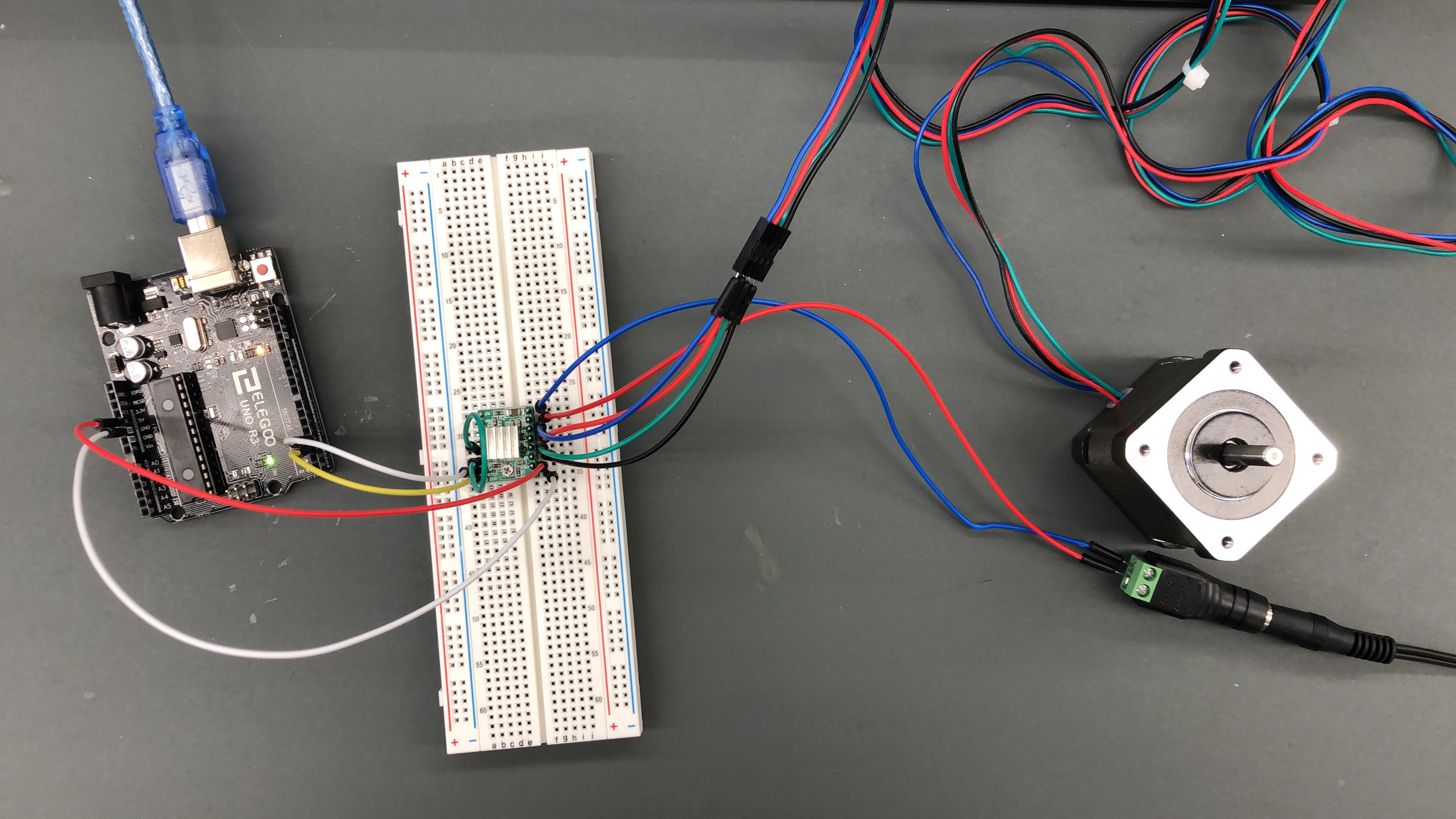
We also worked on moving a single axis, we used a A4988 stepper motor driver
to control the speed and rotation of the stepper motor (Nema17). Below is the pin configuration:
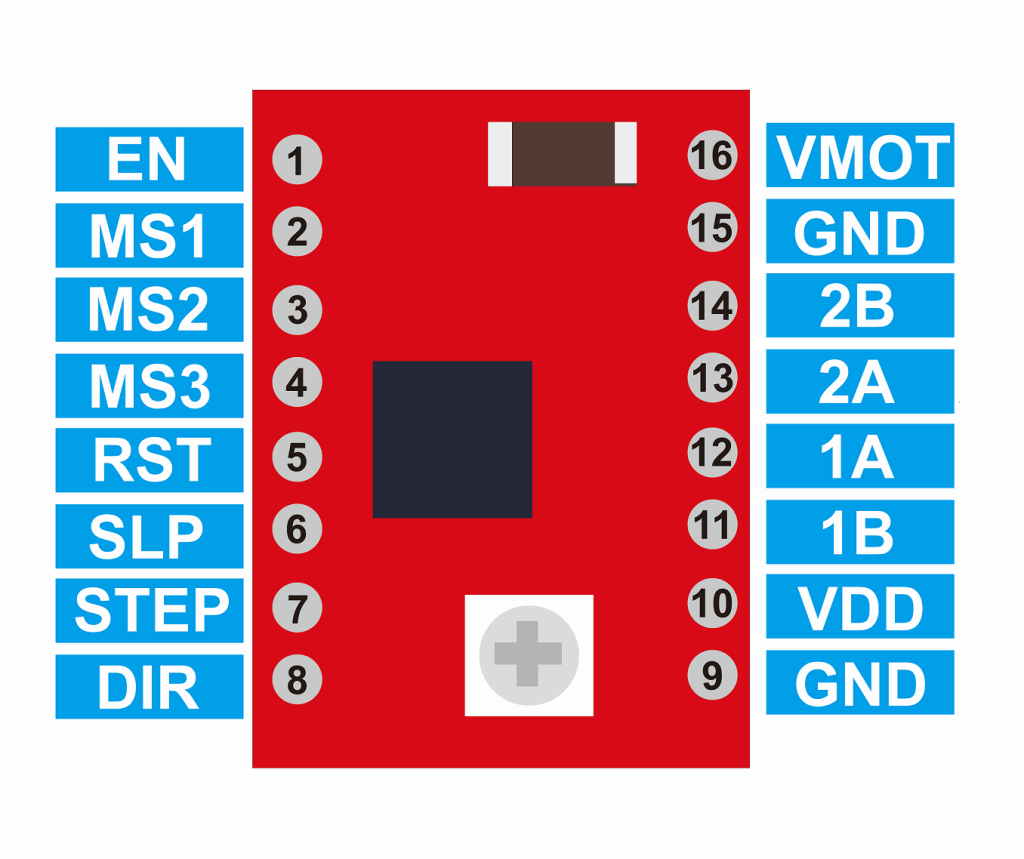
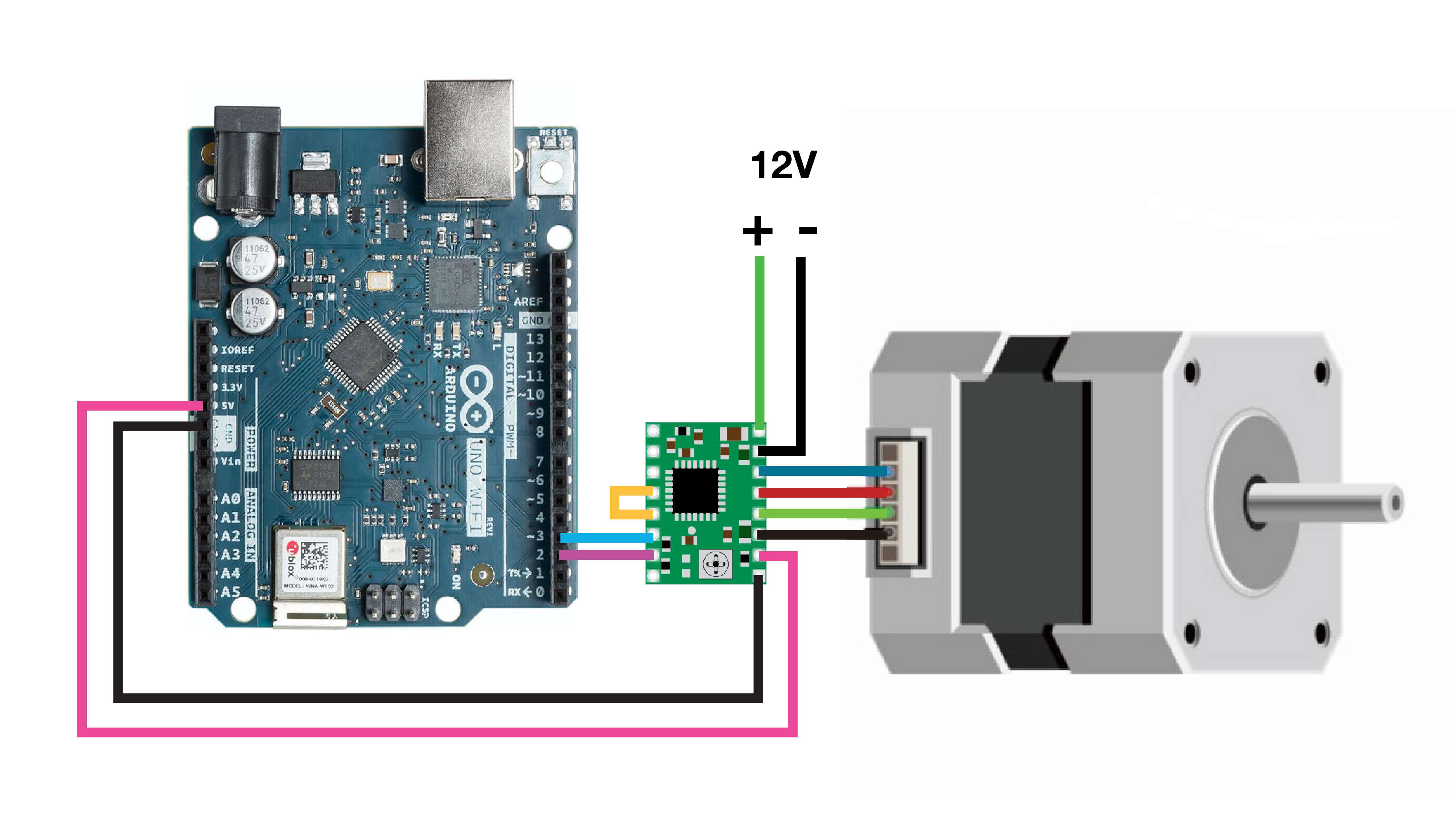
- VDD & GND : Connected to 5V and GND of Controller
- VMOT & GND :Used to power the motor
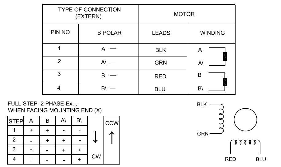
- 1A, 1B, 2A, 2B :Connected to the 4 coils of motor
- DIRECTION : Motor direction control pin
- STEP : Steps control pin
- MS1, MS2, MS3 : Microstep selection pins
- SLEEP : Pins for controlling power states
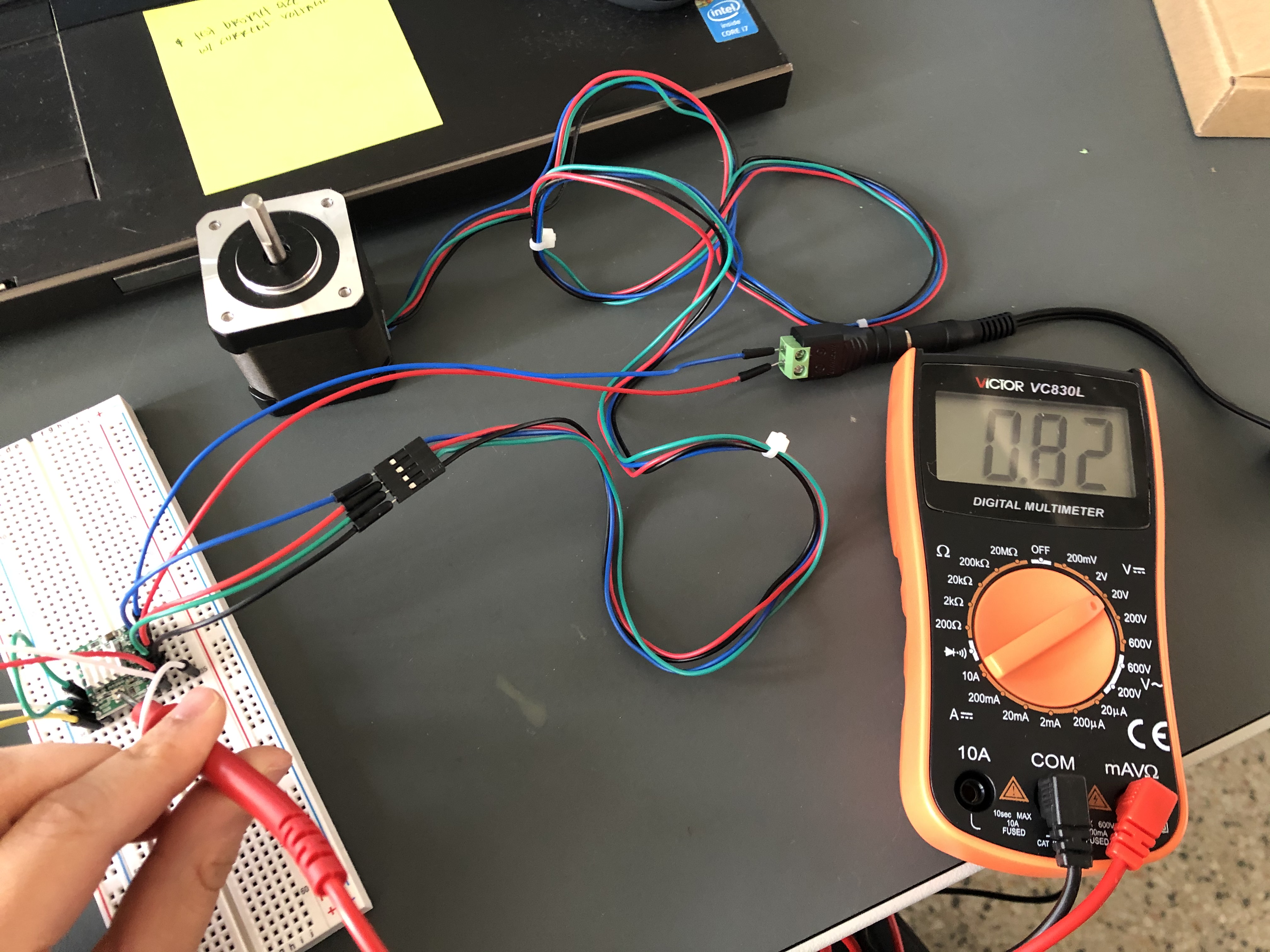
Current Limit = Vref x 2.5
Nema17 = 2A (as extracted from the data sheet - from the following
website )
2 = Vref x 2.5
Vref = 0.8V