


![]()
INPUT DEVICES
The assignment this week was to measure something by adding a sensor to a microcontroller board and
reading it. I had a couple of ideas to try and get started on my final project, but the main concepts
behind motion detection in a network will be taught mainly in ELEVEN: Networking and Communications.
I took this as a chance to learn about different types of input devices (sensors and peripherals) and test
out a couple of the sample boards that Neil included on this week's page.
The first sensor I made this week was the board that measured the light reflection off of your finger
using synchronous detection.
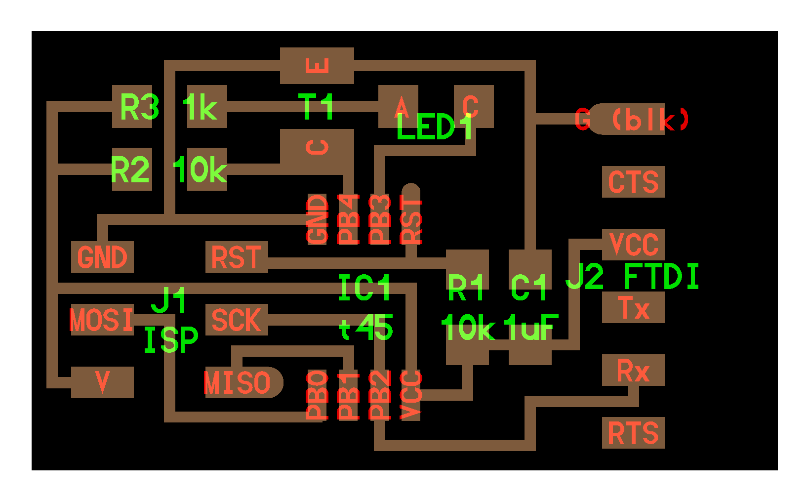
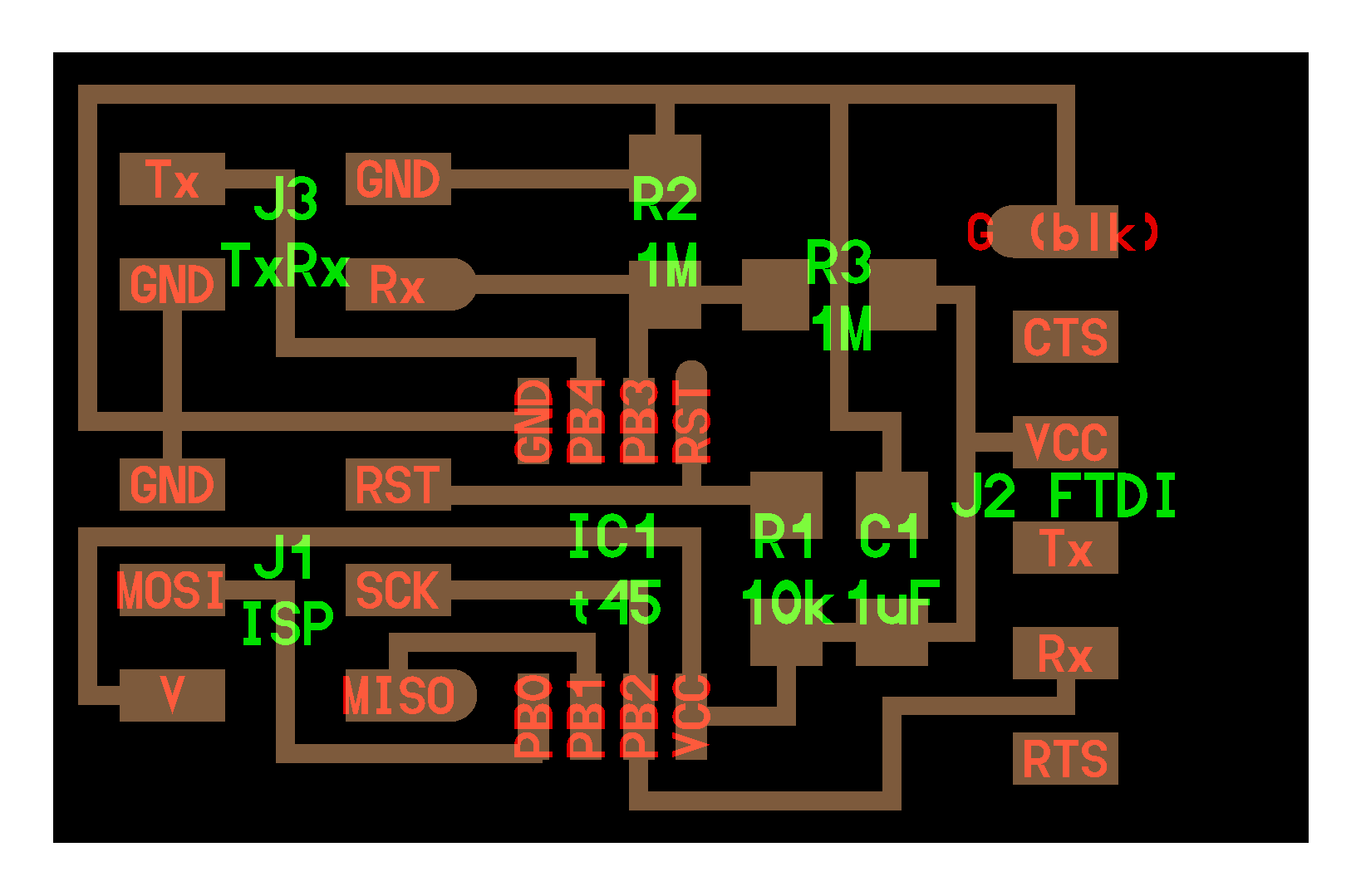
The second board used a step response
to transmit-receive using your finger as a capacitor.

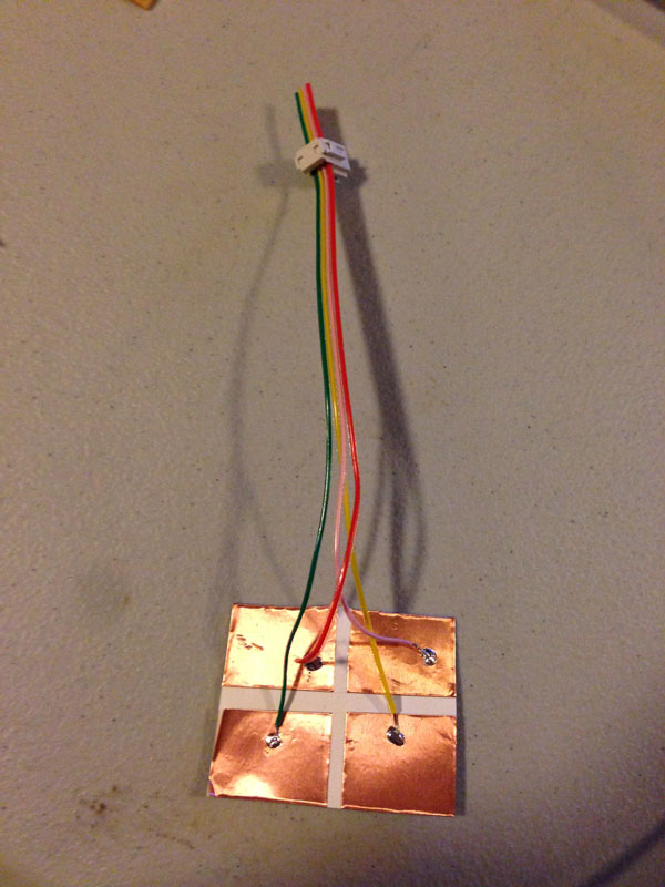
To make the electrode pad, I just cut up some of the copper sheets for vinyl cutting and used some scrap
ribbon cable to make a 2x2 connector to the J3 TxRx connector on the step response board. On the electrode
board, if the wires point upward, the upper left (red wire) electrode connects to the Rx pin on the board.
Moving clockwise from the upper left, the pads connect to Rx (red), GND1
(pink), GND2 (yellow), and Tx
(green).
I had a lot of difficulty because I had accidentally set the low fuse to 0x7E, rendering the ATtiny45V
essentially useless without an external clock. TA Dan helped me to troubleshoot my boards, and after
swapping them out, things started to work. I had previously installed pySerial v2.6
to run term.py
from the Embedded Programming
week. You can follow the instructions on the Python Documentation site
to install the pySerial library to enable Python to interact with the USB serial ports. The library
needs to be installed before running any of Neil's scripts.
In the directory with your .c and .make files, use the commands
make -f [filename].make
sudo make -f [filename].make program-usbtiny
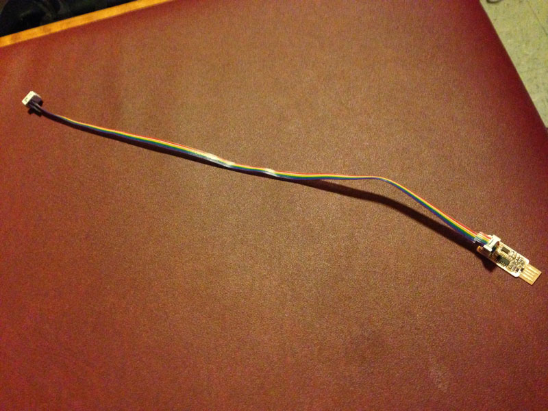
to program the new board using the FabISPkey (or any other programmer of your choice). If you get errors
similar to errors from previous weeks, make sure that your colorful cable connecting the FabISPkey and the
board is corrected in the right direction, shown in the picture below. Also, make sure that the GND on the
FTDI connector and the piece on the board match. Typically, if the FTDI piece is at the right of the board,
the top pin is GND and should connect to the black wire on the connector. For the phototransistor board,
make sure that the mitered corner points toward the 2x3 connector for the ISP. The phototransistor is
directional so the collector and emitter need to point in the right direction. Check the datasheet for
confirmation. Lastly, you can try reflowing all the components to make sure that all the solder is shiny.
I actually accidentally put a 49.9 ohm resistor (labeled 49R9) onto my board instead of a 49.9 kilooohm
resistor (4992) which helped to explain why the LED was blinking, but the phototransistor was petering out
soon after the hello.reflect.45.py program started. If you successfully load one of the sample programs on,
the message should read:
Nicoles-MacBook-Pro:REFLECT njwang$ sudo make -f hello.reflect.45.make program-usbtiny
Password:
avr-objcopy -O ihex hello.reflect.45.out hello.reflect.45.c.hex;\
avr-size --mcu=attiny45 --format=avr hello.reflect.45.out
AVR Memory Usage
----------------
Device: attiny45
Program: 654 bytes (16.0% Full)
(.text + .data + .bootloader)
Data: 5 bytes (2.0% Full)
(.data + .bss + .noinit)
avrdude -p t45 -P usb -c usbtiny -U flash:w:hello.reflect.45.c.hex
davrdude: AVR device initialized and ready to accept instructions
Reading | ################################################## | 100% 0.00s
avrdude: Device signature = 0x1e9206
avrdude: NOTE: FLASH memory has been specified, an erase cycle will be performed
To disable this feature, specify the -D option.
avrdude: erasing chip
avrdude: reading input file "hello.reflect.45.c.hex"
avrdude: input file hello.reflect.45.c.hex auto detected as Intel Hex
avrdude: writing flash (654 bytes):
Writing | ################################################## | 100% 0.62s
avrdude: 654 bytes of flash written
avrdude: verifying flash memory against hello.reflect.45.c.hex:
avrdude: load data flash data from input file hello.reflect.45.c.hex:
avrdude: input file hello.reflect.45.c.hex auto detected as Intel Hex
avrdude: input file hello.reflect.45.c.hex contains 654 bytes
avrdude: reading on-chip flash data:
Reading | ################################################## | 100% 0.37s
avrdude: verifying ...
avrdude: 654 bytes of flash verified
avrdude: safemode: Fuses OK
avrdude done. Thank you.
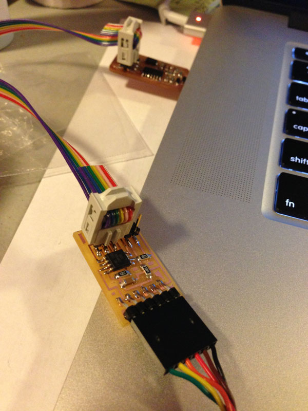
[NOTE: The MISO pin is connected to the purple wire on my rainbow ribbon cable in the picture above.]
To run Neil's programs, type
python [filename].py /dev/tty.usbserial-FTF61CCD
into Terminal (on Mac OS X). You can hit the Tab key after
python [filename].py /dev/tty.
and the computer will automatically find the serial port that the FTDI cable is connected to.
Another thing I learned this week is that there are 3V3 (3.3V) FTDI USB serial connectors
and 5V connectors.
TA Dan originally suspected that the 3V3 cable might have been the suspect as to why my boards initially
did not work, but in the end, we found out that for these simple sensor boards, it does not matter.
The working boards in action [:)] :
IMG 0136 from Nicole Wang on Vimeo.
IMG 0127 from Nicole Wang on Vimeo.
The step response board signal shoots up when both the Rx (red) and Tx
(green) electrodes are contacted. The GUI block also drops when you use your
fingers to connect the Rx and GND pads.