


![]()
ELECTRONICS DESIGN: PART TWO
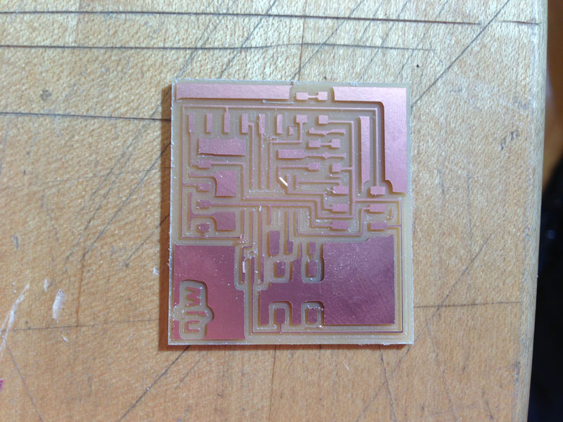
This week, we programmed the boards we made two weeks ago to do something cool! I redesigned my board
because, as I tried to program my board at that time, I discovered that there were still pads connected
to traces underneath the ATtiny44A.
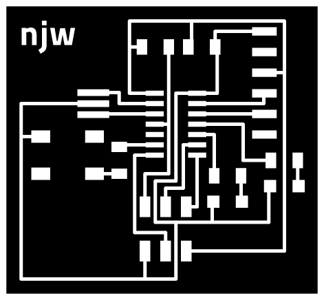
The PNG I sent for milling was a little fuzzier than I would have liked since Illustrator did not want
to export it at the right crop size so the traces were a little thin.


I spent much of the weekend trying to troubleshoot my board. I started off following the picture
that was on the programming the hello.ftdi.44.echo board
page. There were many errors:
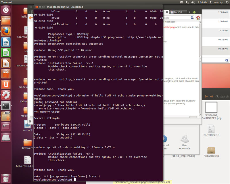
The first error came from the fact that I plugged in both the FTDI connector AND the 2x3 header in
the wrong way. The black wire for the FTDI cable is the ground wire so make sure to check with
your schematic to see which connector pin is "GND"! The second error came from grabbing the wrong
microprocessor. Instead of soldering on the ATtiny44A, I had put on the ATtiny84. As luck would
have it, I then carelessly pulled off the FTDI connector and tore the traces connecting it to the
PCB. I remade the board again and used a hot glue gun to (permanently) secure the FTDI connector
to the PCB. Since I lifted the 2x3 header off the board slightly today, I will be sure to use the
hot glue gun with that piece next time as well.
![]()
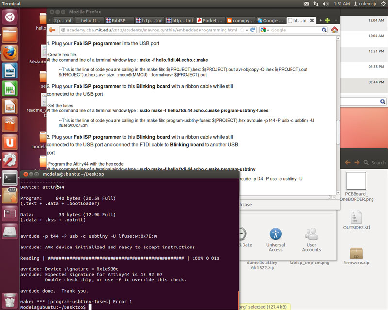
SUCCESS!! The first time
$ sudo make -f hello.ftdi.44.echo.c.make program-usbtiny-fuses
worked was super exciting! After so many little things not working, it was very pleasing to see everything finally coming together. I programmed the echo hello-world board to run the Python script (which decided not to work the first ten times I tried at the Linux terminal in the Architecture FabLab). Make sure you download CrossPack for AVR Development for Mac OS X AND the FTDI drivers. I tried to run
python term.py /dev/tty.usbserial-FTF61CCD 115200
but it did not work since I had not installed the correct drivers. FTF61CCD is the FTDI Serial Number, and 115200 is the baud rate. A quick tip about Terminal in Mac OS X: the command
system_profiler SPUSBDataType
is Mac equivalent to the Linux command
lsusb
Here is my slightly modified version of blink.c from Jeremy and with help from TA Brian. The Makefile that I used to program my board came from Brian's website with a couple of changes based on the specific components on the PCB I made. [Note: The links for the files are embedded in the text!!]
BLINK REVISED from Nicole Wang on Vimeo.
Brian's Makefile makes life much simpler. If you make a file called Makefile (no extension), you can
simply use the workflow
make clean
make
make fuses
make install
to install the program onto your PCB. [Note: You only need to make fuses
once!]
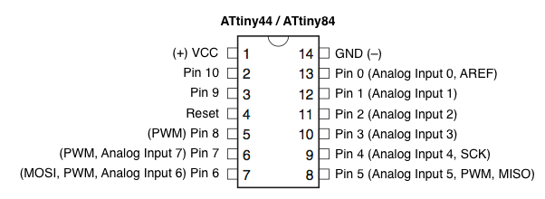
You should also use these diagrams to help you locate the right pins to put into your code for the LED
and the button. Notice that there are two ports as well, designed in the code as PORTA and PORTB.
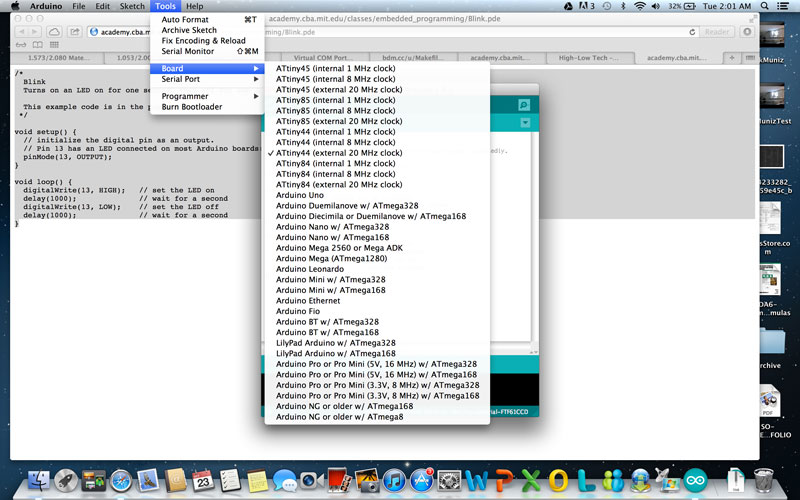
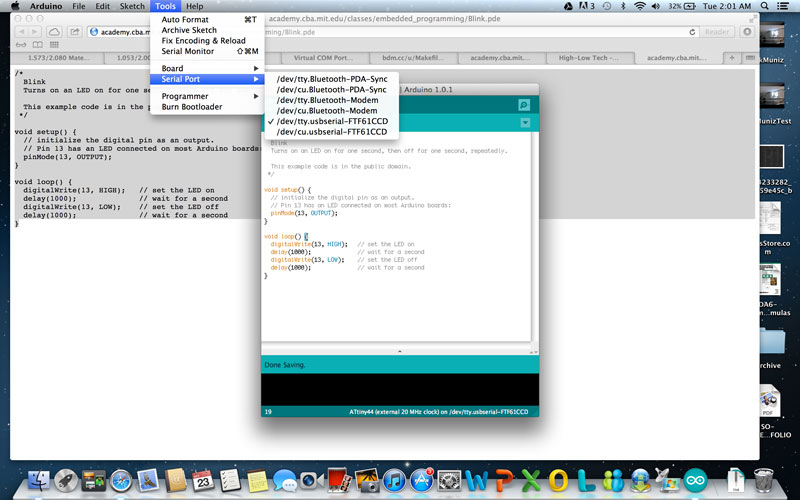
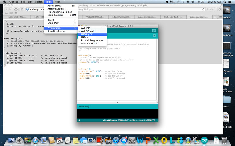
I also tried programming my PCB in the Arduino
platform. Arduino still uses C, and since I have experience programming in Java, it is starting to make
more sense to me. You can simply use the drop-down menu to select your board, serial port, and
programmer. Hit "Burn Bootloader", upload your code, and you are all set!
I also looked into trying the AVR Eclipse Plugin
as well as AVR Assembler, but for now, I think
that just coding in C using TextWrangler will give me enough range and comfort to work and program :).
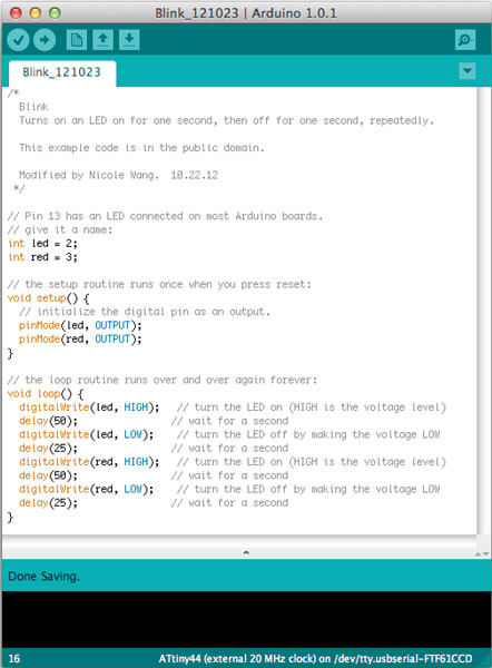
/*
Blink
Turns on an LED on for one second, then off for one second, repeatedly.
This example code is in the public domain.
Modified by Nicole Wang. 10.22.12
*/
int led = 2;
int red = 3;
void setup() {
pinMode(led, OUTPUT);
pinMode(red, OUTPUT);
}
void loop() {
digitalWrite(led, HIGH);
delay(50);
digitalWrite(led, LOW);
delay(25);
digitalWrite(red, HIGH);
delay(50);
digitalWrite(red, LOW);
delay(25);
}
BLINK::IMG 0008 from Nicole Wang on Vimeo.
I was trying, from the beginning, to get my PCB to become more "responsive". I wanted it to record
my actions (button pushing - number of pushes within a certain time frame) and repeat it back to me
using LED flashes. I struggled a little bit trying to understand how timers and counters work in the
AVR programming environment. The led-blink.c
code starts to try to understand how to initialize and use timers to control LED blinking using
registers (thanks to the AWESOME tutorial from maxEmbedded.
LED BLINK from Nicole Wang on Vimeo.