/ / / / / / / / / / / / / / / / / / / / / / / / / / / / / / / / / / / / / / / / / / / / / / / / / / / / / / / / / / / / / / / / / / / / / / / / / / / / / / / / / / / / / / / / / / / / / / / / / / / /
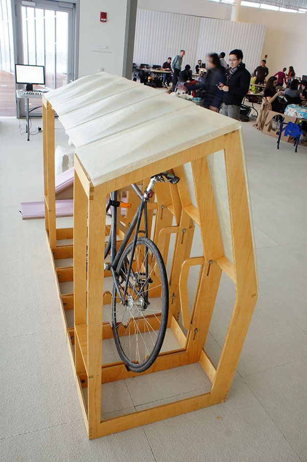
final project update + development
/ / / / / / Update - December 4, 2013:
Here are the steps I need to take in order to finish the Bike House:
1. Apply at least two coats of varnish on the plywood frame for weather-ability (I've already accomplished this step).
2. Lay up five more composite roofing panels. I've already ordered additional fiberglass cloth from the distributor and just need to go into production mode.
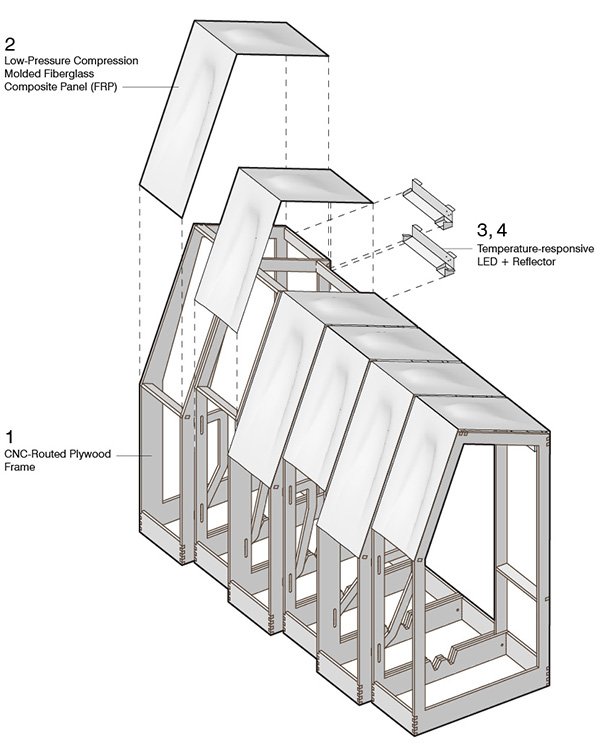
3. Create an electronics schematic and board layout for battery-powered LED light fixtures. I want it to be bright enough to make the translucent panels glow at night. I'll build off of my LED experimentation from previous weeks, although I'm probably going to need to obtain more powerful lights. This step also includes programming an input into the light fixture-- for now, I'm planning on using a proximity sensor to activate the lights. If I have time I'd love to incorporate a color-changing operation, perhaps actuated by a humidity sensor, or at the very least, a button.
4. Next step is to make a simple reflective housing for the lights using the Omax water jet cutter on sheet aluminum.
5. Lastly, if I have time I'd like to incorporate tensioning rod and fittings in order to make the frame more laterally stable.
/ / / / / / Final Development - December 17, 2013
The following documents the work that went into the final development of my bike house. Thanks so much to the helpful TAs who offered their time and assistance along the course of the final project: David, James, Matt-- thanks!!! And thanks to Pauline for being an awesome electronics guru.
Varnishing the plywood frame
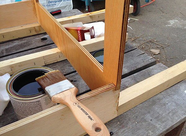
I bought some marine-grade spar varnish from a local hardware store, and applied two coats, sanding lightly in between. I thought I might have needed more coats, but the finish was nice and seemed fairly weather resistant after two, so I stopped and moved on to the next task...
Laying up the remaining five composite panels:
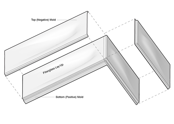
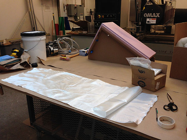
Using 6 oz. fiberglass cloth which I purchased from Jamestown, I repeated the same process as I did during composites week:
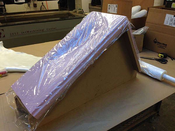
1) place cellophane release film on bottom mold
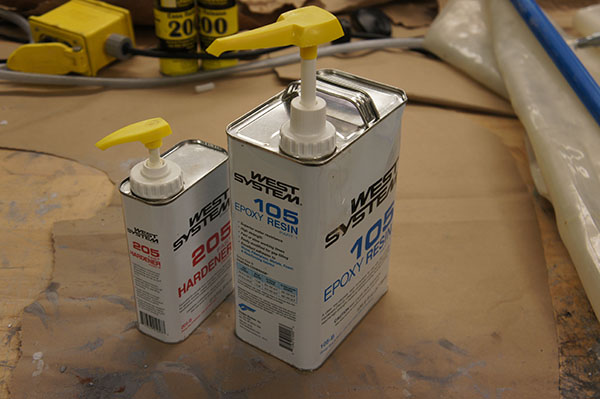
2) wet up three layers of fiberglass with West Systems fast drying epoxy
3) place wet fiberglass on cellophane on mold
4) place perforated cellophane (bleeder layer) on fiberglass
5) place breather layer (polyester batting)
6) apply one more layer of cellophane release film
7) apply top mold closures
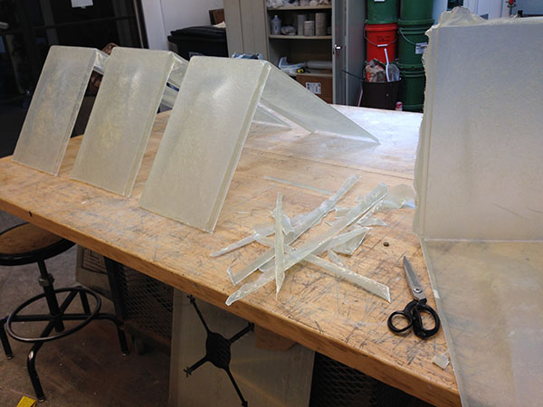
Here are some of the panels being cut. Scissors ended up being the quickest and neatest way to trim the excess fiberglass off. This also produces less hazardous fiberglass dust than band-sawing.
Designing and testing the electronics
In order to properly illuminate the structure with some kind of environmental input (in this case, temperature), I had to determine the best way to achieve brightness and accomplish the sensing. For temperature input, I used a thermistor and developed a board design based on Neil's "hello temp" example from input devices week. .
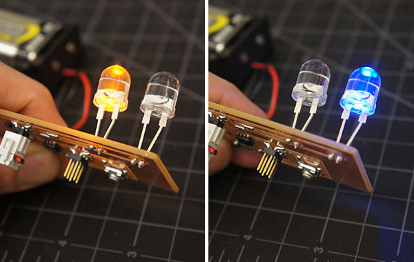
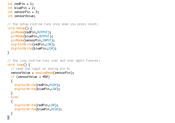
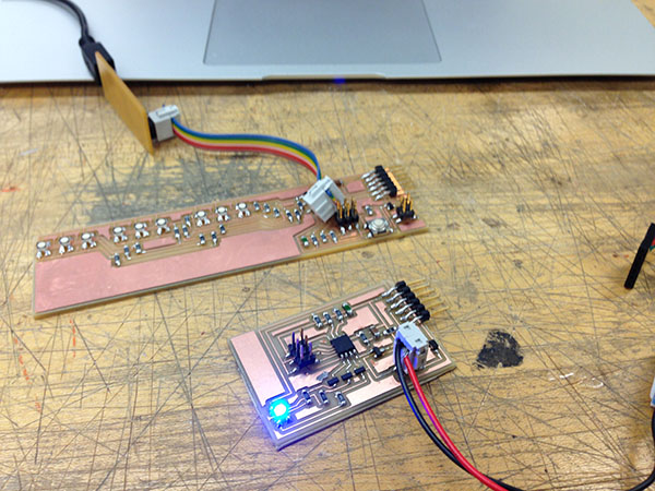
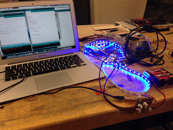
I made a prototype board as a proof of concept using through-hole LED's that one of the TAs gave me. Below is a simple code written in Arduino IDE to write to one color when the temperature threshold is below a specific voltage, and write to the other when above. I programmed the above through-hole board as well as a board with a single RGB, as shown in the video below.
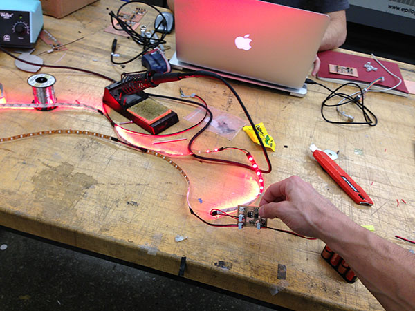
Next, time to scale up. I went through a frustrating round of failed LED array boards-- not bright enough, some burnt out, others just didn't work. Below, a couple of trial runs.
After some debugging efforts, I decided o place an order with SuperbrightLEDs for pre-assembled flexible strips for two colors. They arrived just in time! I redesigned my board to incorporate two 2x2 headers, one going to each LED strip. Here's the schematic and final traces:
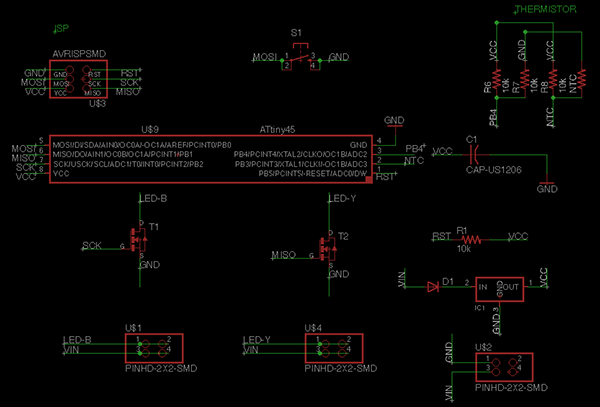
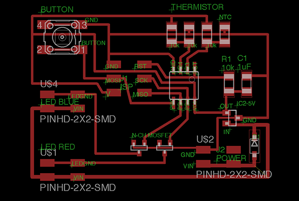
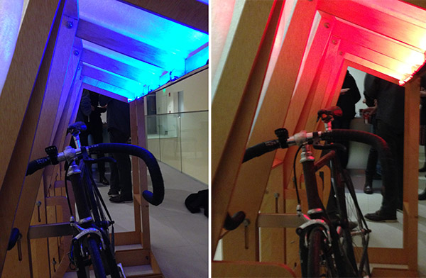
The LEDs are made to be powered by 12v. The blue is brighter than the red light but both were just fine in terms of brightness for my application. Each are connected on the positive side directly to battery power (unregulated), and on the negative side to an analog input pin on the microcontroller after going through a MOSFET. The thermistor temperature sensor and associated resistors connects to another input pin.
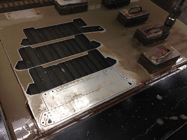
The photo above shows how I cut the long strips into shorter lengths to fit neatly into each "bay" between structural members. I soldered wire connections in between each length of LED. Below, I set up a cad file for the reflective housings to be cut out of 1/32" sheet aluminum, on the Omax water-jet cutter.
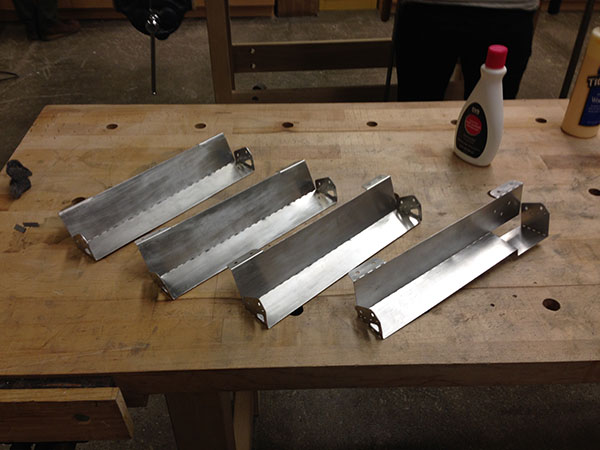
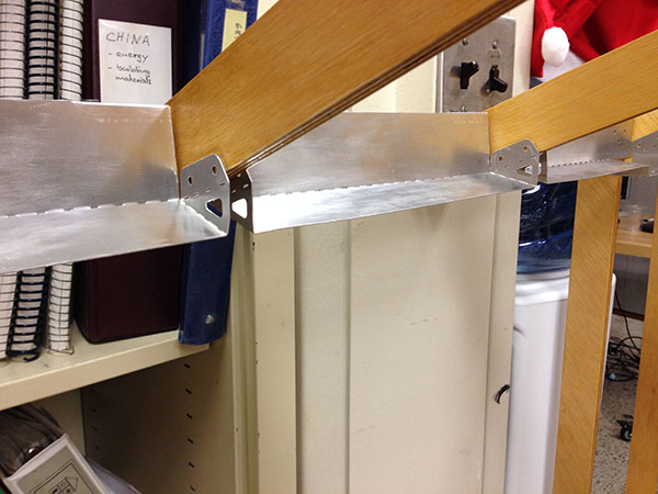
Here are the finished pieces. I ran them over with steel wool and a dab of acetone, to give them a cleaner and brushed finish. I folded the tabs on the break metal machine.
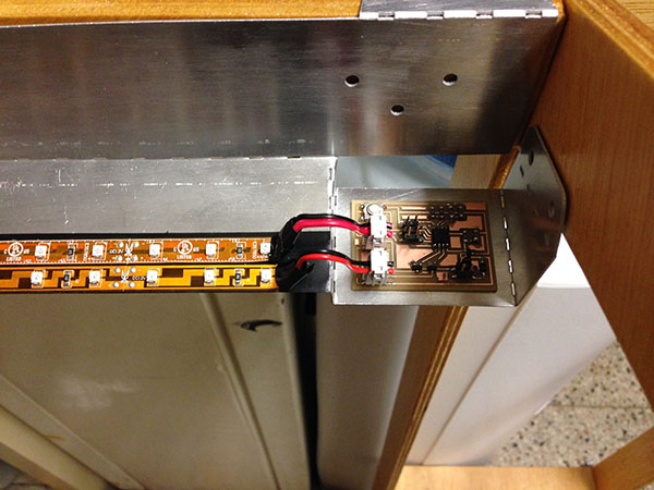
I laid down some electrical tape and then used the adhesive backing of the LED's to fasten them to the reflectors. The last reflector has a dip to accept the thermistor board.
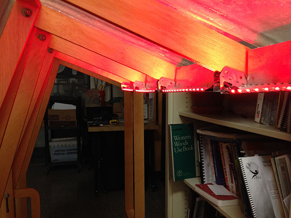
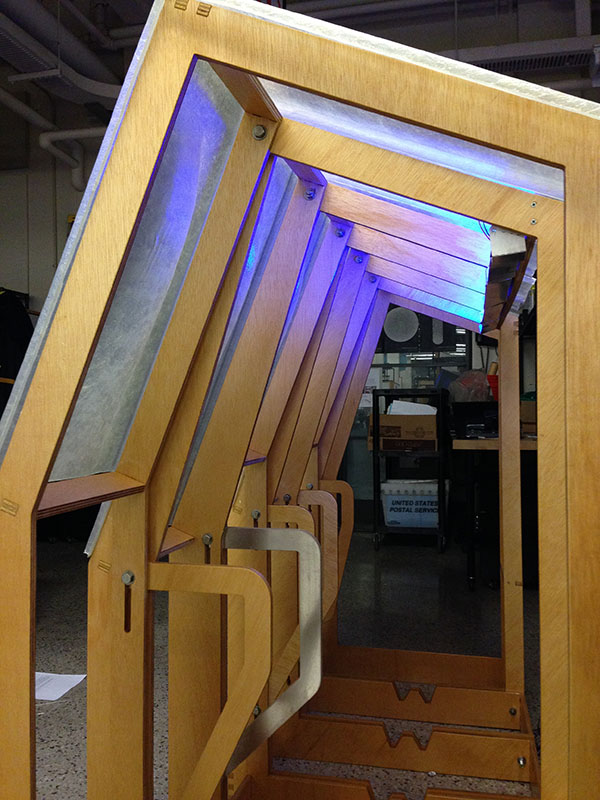
Testing the lighting, temperature sensor, and reflectors in my studio. I was happy with the results! 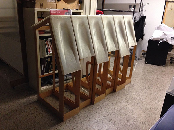
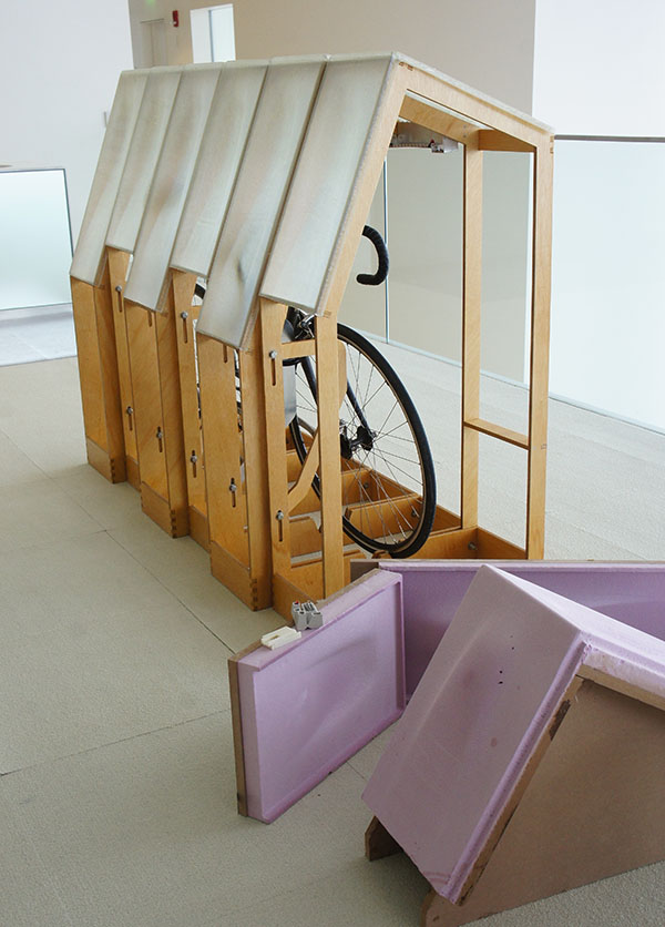
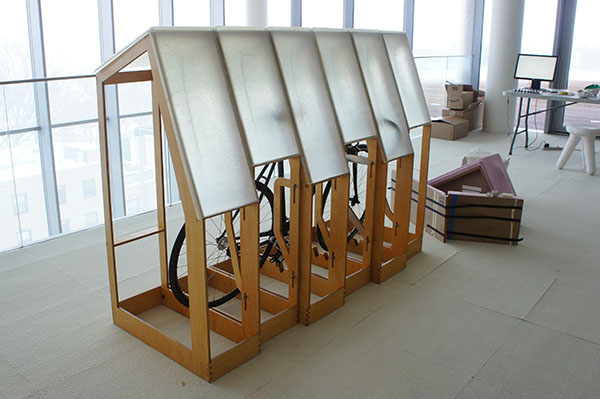
Last, I fastened the composite panels back to the frame using plywood screws.
Here are some closing thoughts about what I liked and what I would have done differently if I'd had more time:
1) Plywood Frame -- I would have thought a bit more about contact with the ground (less is more) and lateral stability. Also, making the whole structure modular (able to be easily assembled / disassembled into bays, even with the roofing attached) would have been cool! Next version...
2) Composites -- I was very happy with the two-part mold and translucent finish of the fiberglass. The panels definitely translate plenty of wrinkles and imperfections from the mold release film, so it would be best to use something smoother and sturdier than cellophane, and it would have been a good idea to do some tests with different geometries (depth of complex curvature, other shapes) to evaluate what geometries yield smoother finishes. Also, it would be great to think about how the panels fasten to the frame prior to cutting, so that the right hardware can be ordered in time and that they all come together nicely.
3) Electronics -- After receiving the LED strips, I realized that I probably shouldn't have spent so much time trying to make my own on the Models. It would have been cool to either incorporate more light inputs for more steps of colors when the temperature changes, or to have completely gone with addressable RGB strips. Also, remember to always check the performance of your input and output devices on presentation day!
4) When you make something big, have a plan for transporting it! This is something I overlooked due to Finals craziness, and will have to address tomorrow...
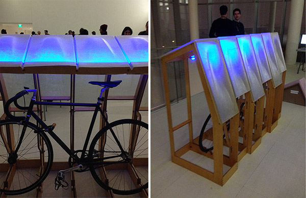
Here are some photos from the final presentation. More photos are available on my flickr set. Thanks for reading!