/ / / / / / / / / / / / / / / / / / / / / / / / / / / / / / / / / / / / / / / / / / / / / / / / / / / / / / / / / / / / / / / / / / / / / / / / / / / / / / / / / / / / / / / / / / / / / / / / / / / /
week 10 / input devices
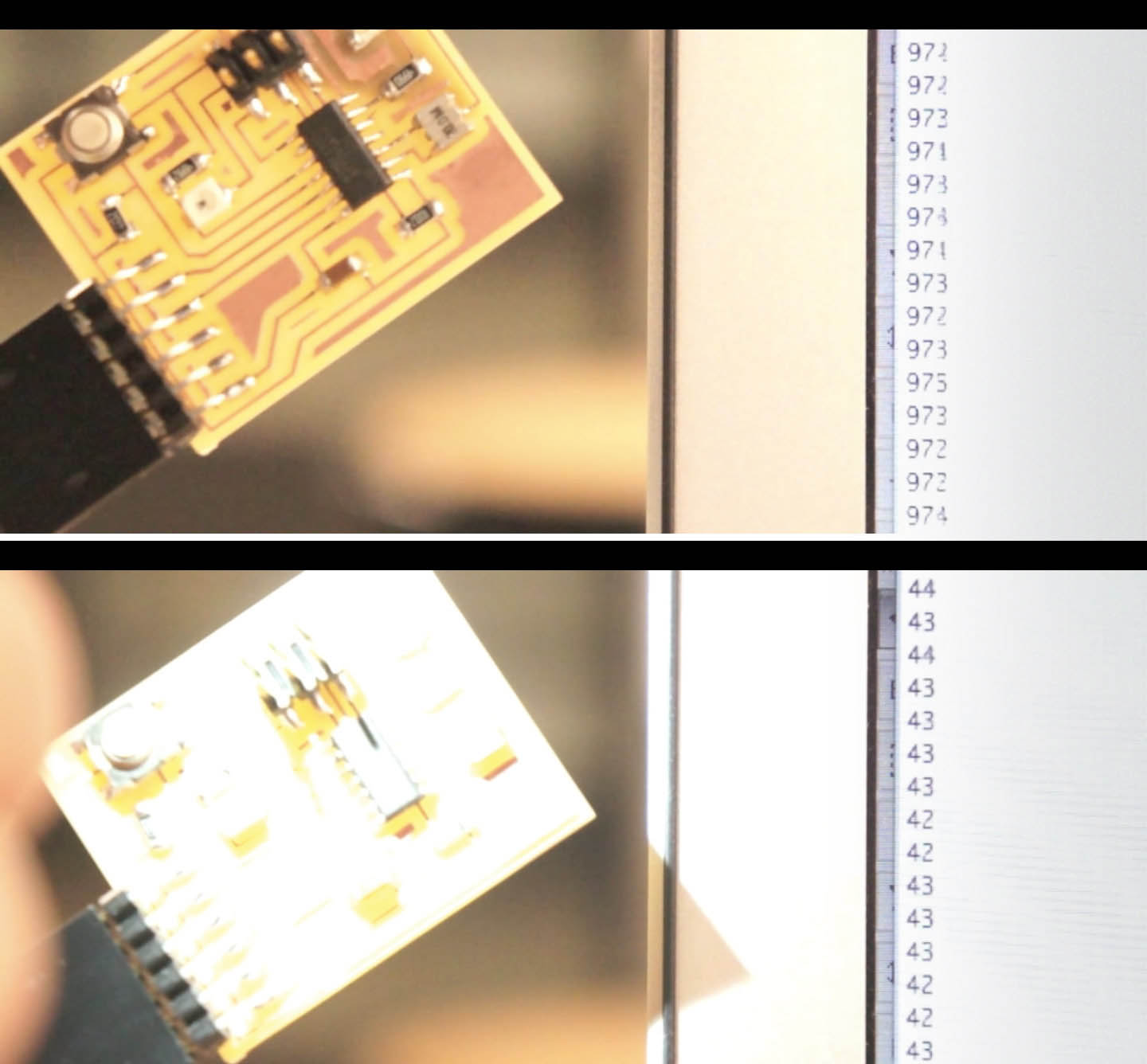
This week I made a light sensor using the class example board from the class website, and then used the wiring concept to modify a board that I had already designed and equip it with a light sensor.
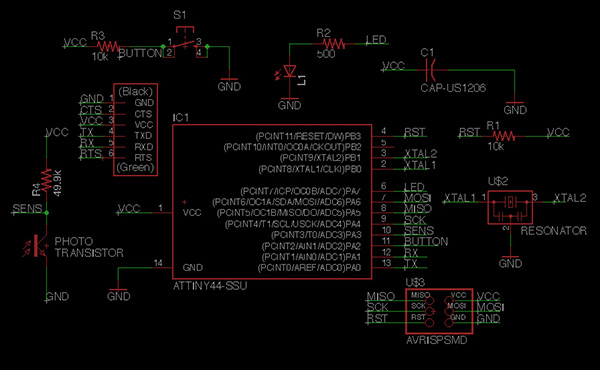
I added a phototransistor and resistor to the schematic board I had previously used during embedded programming, and followed the circuitry orientation and order from the class example. I tied in the "collector" end of the phototransistor to one of the open analog inpots on my ATTiny 44 Microcontroller.
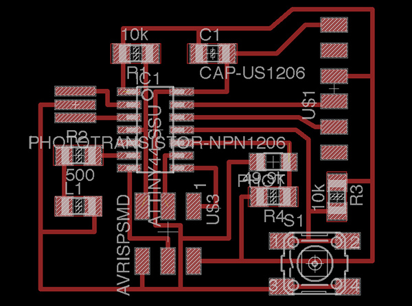
Routing the traces to include the phototransistor and its resistor was tough. After many failed attempts at keeping the paths from crossing, I found the best way to set up the traces was to re-arrange some of the analog inputs; I plugged the phototransistor into where the button was, and then routed the button into one of the open analog inputs. Now everything fits like a glove! As with Electronics Design, I exported to a PNG for the trace and cutout imagery, which I then used on the Modela for milling.
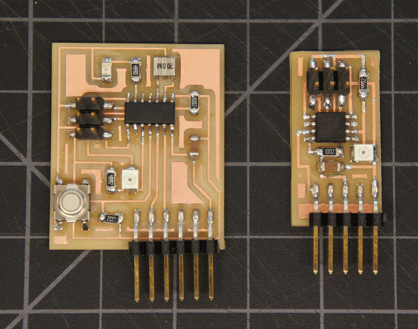
I stuffed and cleaned the board. Here's my board on the left next to Neil's example board, which I made first as a test, on the right. The phototransistor is the white square with a circle in it.
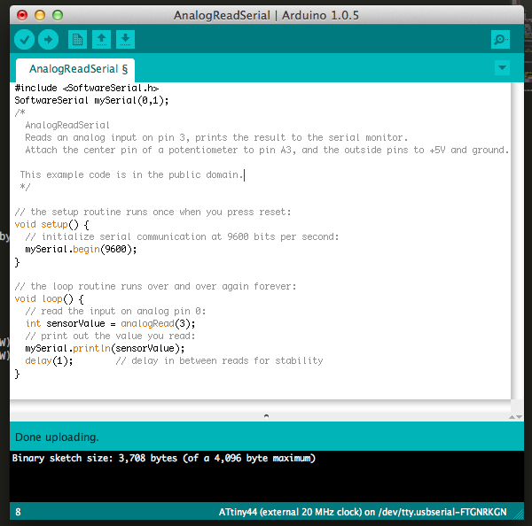
Using Arduino IDE, I modified the AnalogReadSerial code to read the correct input pin (in my case, analog input 3 on the ATTiny 44). I then uploaded the code to my new board using the trusty FabISP as programmer.
As seen here in the Serial Monitor of Arduino, the phototransistor responds to light by reducing the current input to the computer. Thanks to Pauline for helping me with serial communication in Arduino, and to Charles F. for his patient assistance in the Fab Lab.
/ / / / / / / / / /
Eagle Files:
PNG Files: