/ / / / / / / / / / / / / / / / / / / / / / / / / / / / / / / / / / / / / / / / / / / / / / / / / / / / / / / / / / / / / / / / / / / / / / / / / / / / / / / / / / / / / / / / / / / / / / / / / / / /
week 11 / output devices
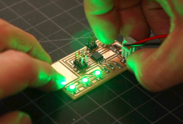
Continuing on the theme of communicating with light using a microcontroller, I made an LED output device. I stepped things up a bit from the LED board I made during electronics design week, and integrated three RGB lights and "plug-in" button.
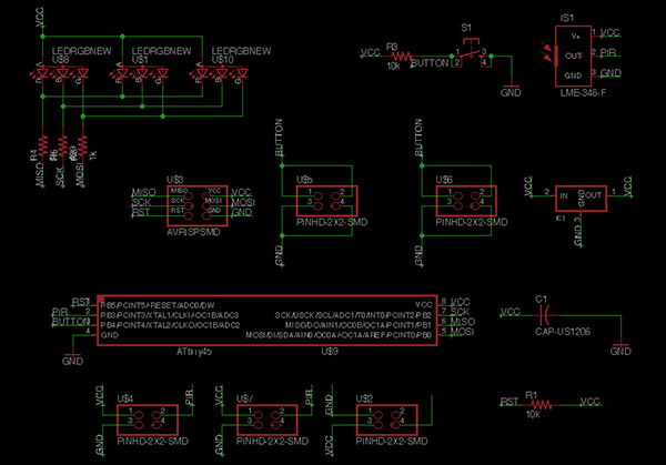
The schematic in Eagle. In the upper left you can see three RGB's strung together through the same set of resistors (one for each color channel). In the upper right you can see a button and pyroelectric infrared (PIR) sensor to be monted on a smaller, separate board. I got to incorproate the button on this week's assignment, and will integrate either a PIR or proximity sensor in my final project.
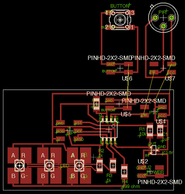
Here's the board layout in Eagle. The RGB array is in the lower right-- the component library I used in Eagle made for some bulky pads for the RGB's. You can see in the upper right how I planned to connect the button and sensor via a four-pin connection and wire, so that the input and output devices are separated (thinking ahead to my final project...).

The way I had set up the space between the RGB pads was too tight, and the Modela couldn't accomplish all of the traces. The same happened to the far right with the 5V regulator (harder to see here). This underlines the importance of checking the tool path preview before milling!
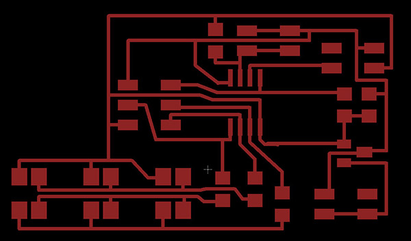
I manually overrode the RGB pads to make them less bulky and provide just a tad more space between the traces (same for the regulator).
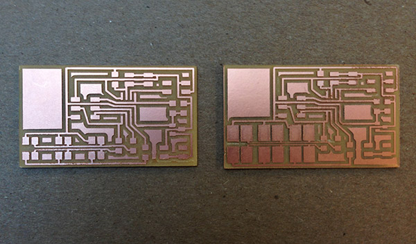
It worked... the good board is on the left. You can see on the right that I tried clearing out some of the troubled areas under the RGB with an exacto knife but the resulting traces were so thin that they started to peel up. I proceeded to assemble the components.
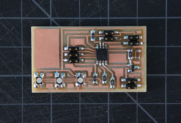
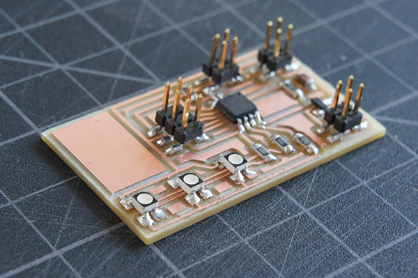
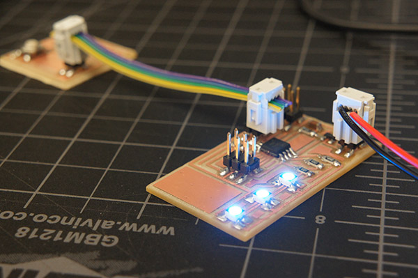
Stuffed and ready to illuminate! In the future I'd like to see how many of these small RGB's I can accommodate with a single MCU (the ATtiny45 can handle 40mA per pin and these particular LED's draw about 20mA of current).
On the programming end, to get the lights to turn on, I ran a few different operations. In the video above, using Terminal, I ran Neil's RGB example from the class page--this makes the lights smoothly transition through a few different color configurations. All three lights illuminate synchronously because the red, green, and blue channels are all running off of the same three pins on the microcontroller.
To Incorporate my "remote" button, I modified an Arduino "bounce" example to make the light change color on every button press, as seen in the video above.
I hope to continue to work on this LED board so that I can embed an array under each roofing panel of my bike shed, to light it up at night. I'd like to actuate the lighting not only with a button, but also with a motion or proximity sensor.
/ / / / / / / / / /
Eagle Files:
PNG Files:
ledRGB_traces.png / ledRGB_cutout.png / Button_traces.png / Button_cutout.png