/ / / / / / / / / / / / / / / / / / / / / / / / / / / / / / / / / / / / / / / / / / / / / / / / / / / / / / / / / / / / / / / / / / / / / / / / / / / / / / / / / / / / / / / / / / / / / / / / / / / /
week 02 / press fit construction kit
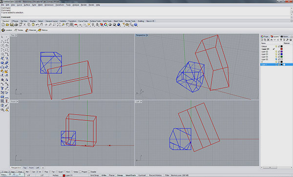
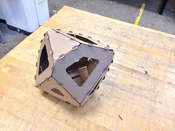
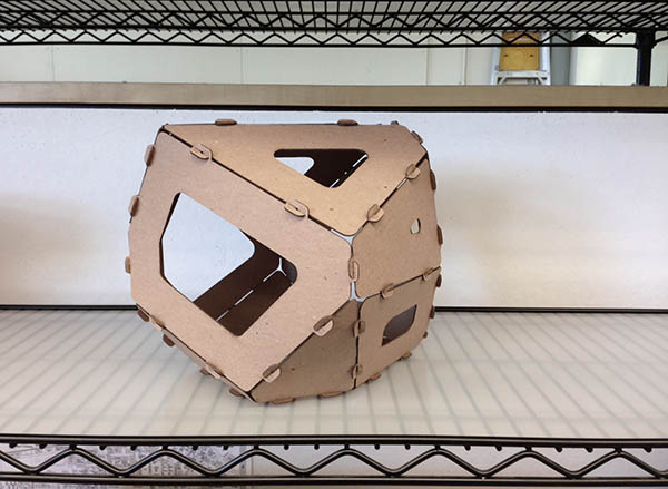
For this assignment, I made a laser-cut prism out of 14-ply chipboard. To start, I modeled a solid cube in Rhino and performed boolean subtraction operations at various angles, creating a prism shape with unique faces.
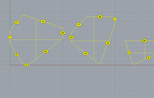
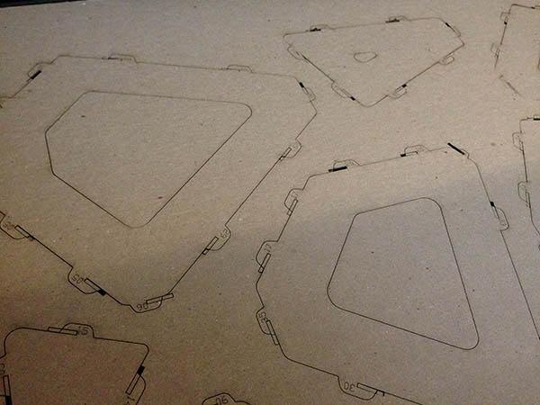
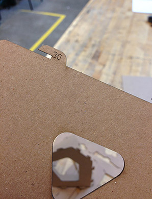
Using the Unroll Surface command, I generated 2d shapes from the 3d geometry and numbered the corresponding sides.
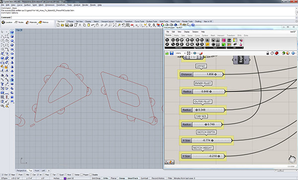
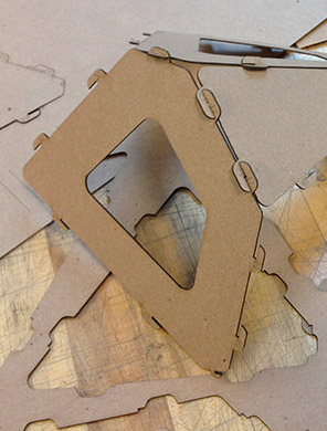
In Grasshopper, I made a definition that creates semi-circular tabs with interlocking slots. I made the tab size and slot thickness/depth parametric (thanks to Carrie for GH help!). I wasn't sure if all of the slots would be oriented the same way, so I attempted to make a universal joint with slots on two sides (below left).
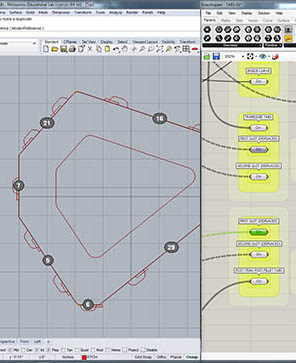
I cut a couple of test pieces and realized that 1) having two slots caused a misalignment of joints, 2) all the slots actually always face the same direction (any two adjacent sides are inherently at 180 degrees from one another), and 3) everything was a tad too big. So I re-worked the Grasshopper definition and set up my cut files.
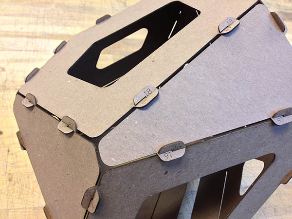
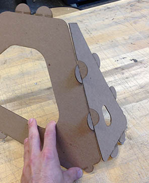
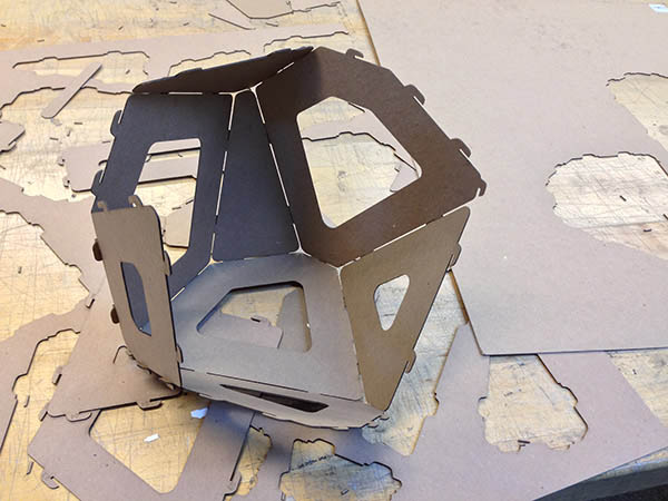
The prism under assembly. Although the slots seemed a tad too loose at first, as the pieces came together, it was clear that the small amount of extra give was necessary to provide flexibility for those last faces to engage.
/ / / / / / / /
Files: