/ / / / / / / / / / / / / / / / / / / / / / / / / / / / / / / / / / / / / / / / / / / / / / / / / / / / / / / / / / / / / / / / / / / / / / / / / / / / / / / / / / / / / / / / / / / / / / / / / / / /
week 04.a / 3d printing and scanning
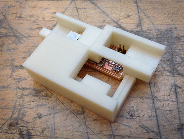
For the 3d Printing portion of this week's assignment, we have to limit the size of our print to something that would fit inside a lacrosse ball. So in an effort to incorporate last week's small-scale handywork, I decided to make a protective case for my mini FabISP microcontroller.
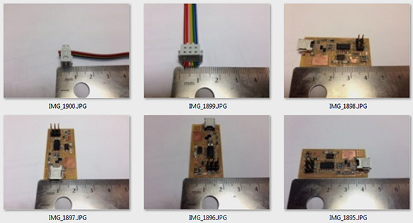
To start, I measured the board and its various components, and modeled the overall shape in Rhino.
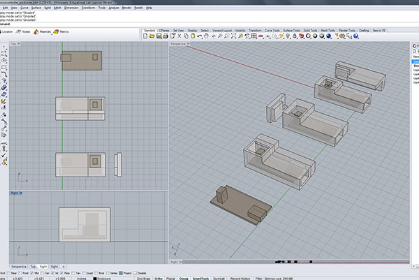
I wanted to design a custom enclosure that fit the circuit board like a tailored suit, so I sketched and modeled through a few variations, each consisting of a place for the board to fit snugly, openings for the 6-pin and micro-usb ports, and press-fit construction, to eliminate the need for fasteners or other materials.
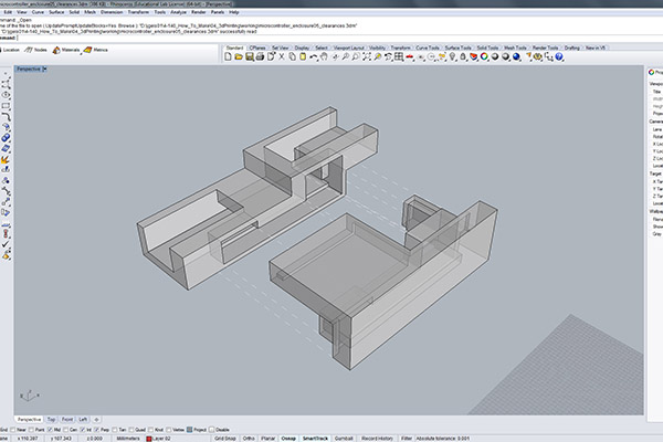
I arrived at a design that I was pleased with, that has interlocking parts and some intricate undercuts, making the case something that, I believe, could not be fabricated "subtractively" (i.e. with a milling machine).

In order to make the positive and negative forms fit together, I built in some tolerance to the model by offseting the surfaces on the negative component by 0.1mm, as recommended by Formlab's guidelines for their Form1 machine (I later learned thatI probably should have gone with more conservative offsets paticular to the machine I was printing to, the Dimension). I exported my .STL to MIT's rapid protyping cue for the Dimension printer, which uses Fused Deposition Modeling technology, heating and extruding fine layers of thermoplastic. And then I waited!
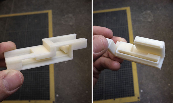
A few days later, after our class section's batch of printing was completed, I retreived my 3d prints. They looked good, but as soon as I tried to snap them together... they wouldn't fit! My tolerances were not quite high enough, and the connections I had designed were too tight to actually interlock. So, I resorted to a bit of last minute filing to remove enough material at the connections to make the pieces join.
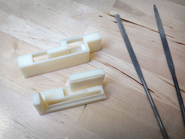
Lesson learned. Though the case works fine after some filing, I hope to tweak the geometry of the pieces in Rhino so that they fit right out of the machine.
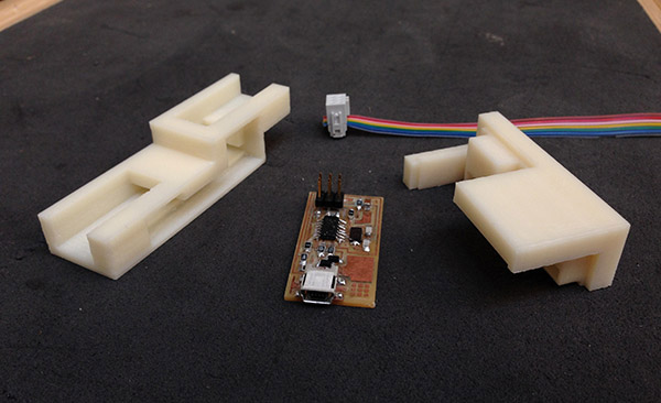
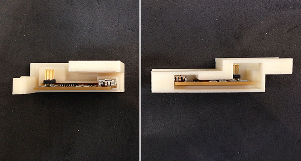
The circuit board fit pretty well into the negatives of the case, although on my next go-round I'll definitely remove some extra solid in the Rhino model so that it's not quite as tight and to prevent any snagging of the soldered components.
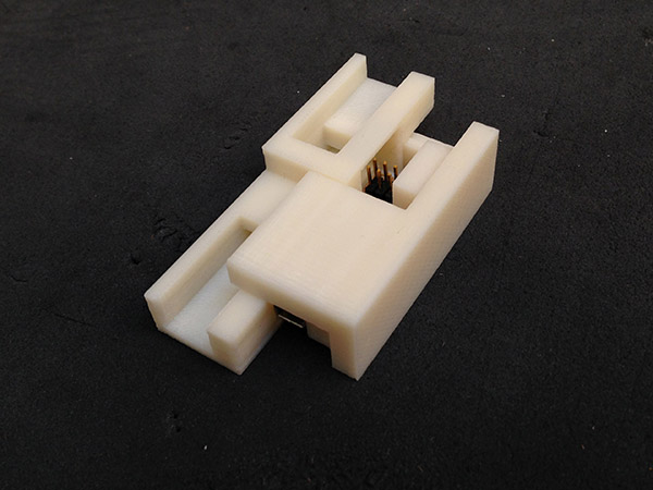
Assembling the case...
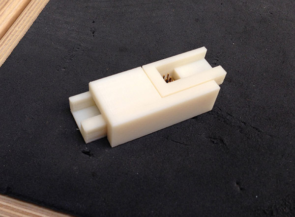
...And snapping it shut!
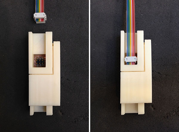
The design incorporates grooved extensions to receive and support the cable inputs.
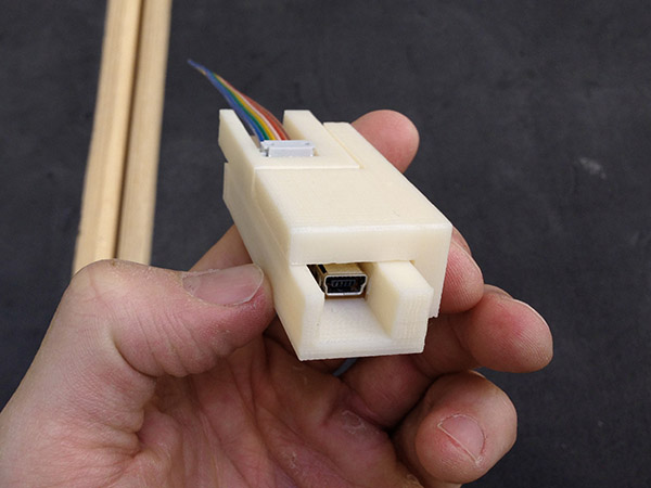
When I model "v2.0" of the case, I'll also tweak the geometry around the microUSB port, to allow a little more breathing room for its cable entry. But all in all, my case gives a bit more protection and sturdiness to the FabISP, and will hopefully serve as a teaching moment and building block for any future projects where I might design an embedded circuit board.
Files:
/ / /
week 04.b / 3d scanning
I scanned one of my niece's toys, a bird whistle, using Autodesk's 123D Catch applicaiton, which creates a 3d model by stitching together a series of photographs of an existing object.
Following the tips on 123D Catch's website, I tacked some reference markers on my object, in this case some cut-up post-it notes, which should help the program stitch the model together more accurately. Also, I printed out a checkered background on which to place the bird, for additional reference points.
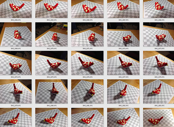
I took about 40 photos of the bird, rotating my camera angle about 10 degrees for each exposure. I then uploaded the photos to the cloud for conversion to a model.
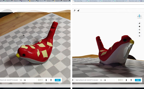
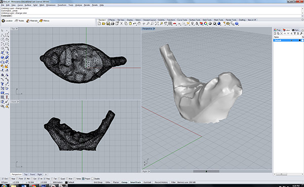
After a few minutes of waiting for the stitching process to finish, I was able to open up the resulting 3d model both in 123D Catch's web interface (with texture maps), and in Rhino as an .STL. It got the overall shape right, although introducing a few craters in the bird's surface here and there. I'm guessing this was a result of the bird's shiny surface texture, which may have introduced anomalies in the modelmaking process.