Introduction
Electromagnets
In a seemingly unconnected flow of things, I have another entirely new final project proposal. That's what happens when "anything" is what you have to choose from. I was thinking of creating a hover board that does not depend on having a magnetized floor that it is bound to. My idea is to have the metal platform that the electromagnetically hovering board floats over, be motorized by wheels. As the bottom board moves, so will the top, hovering board. The issue is that the hovering occurs via repulsion. The trick will be how do I get the bottom board to propel the top board along with it. I plan to reach out to my physics professor to come up with ideas. One though is to have repulsion in the middle of the top board but have the outer regions attracted to the bottom board. This would create an arched vector field and may actually bend the top plate, depending on its rigidity.
Electromagnetic Forces
Background & Research
After the outputs week my final project finally took a definite direction. I will be prototyping a hover board by running a current through an electromagnet and using magnetic field sensors to determine whether the current should be decreased or increased to hover the object. Not one of those hoverboards that rolls around on the ground that took over the world in 2015 and 2016, but a real, Back-to-the-Future type hoverboard.

What's been done before?
There are tons of videos on youtube that show electromagnet in action whether the systems were purchased or homemade.
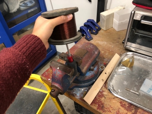
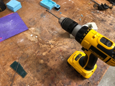
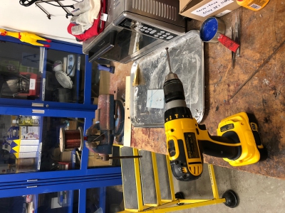
By winding coil around steel and running current through it, you can create an electromagenet. The first step was to wind my magnet. The magenet is strengthened by a factor of N, the number of turns around the coil, and weakend by a factor of 1/l, the length of the magnet. Since hand winding is inefficient and would take a long time to get a lot of turns, Rob in the Harvard shop helped me to make a setup where I used a screwdriver, clamp, and electric drill to make a homemade coil winder. The end result was an electromagnet with about 17 Ω resistance.
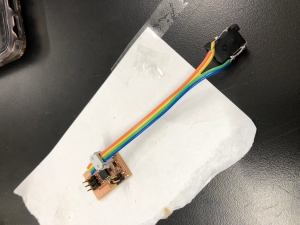
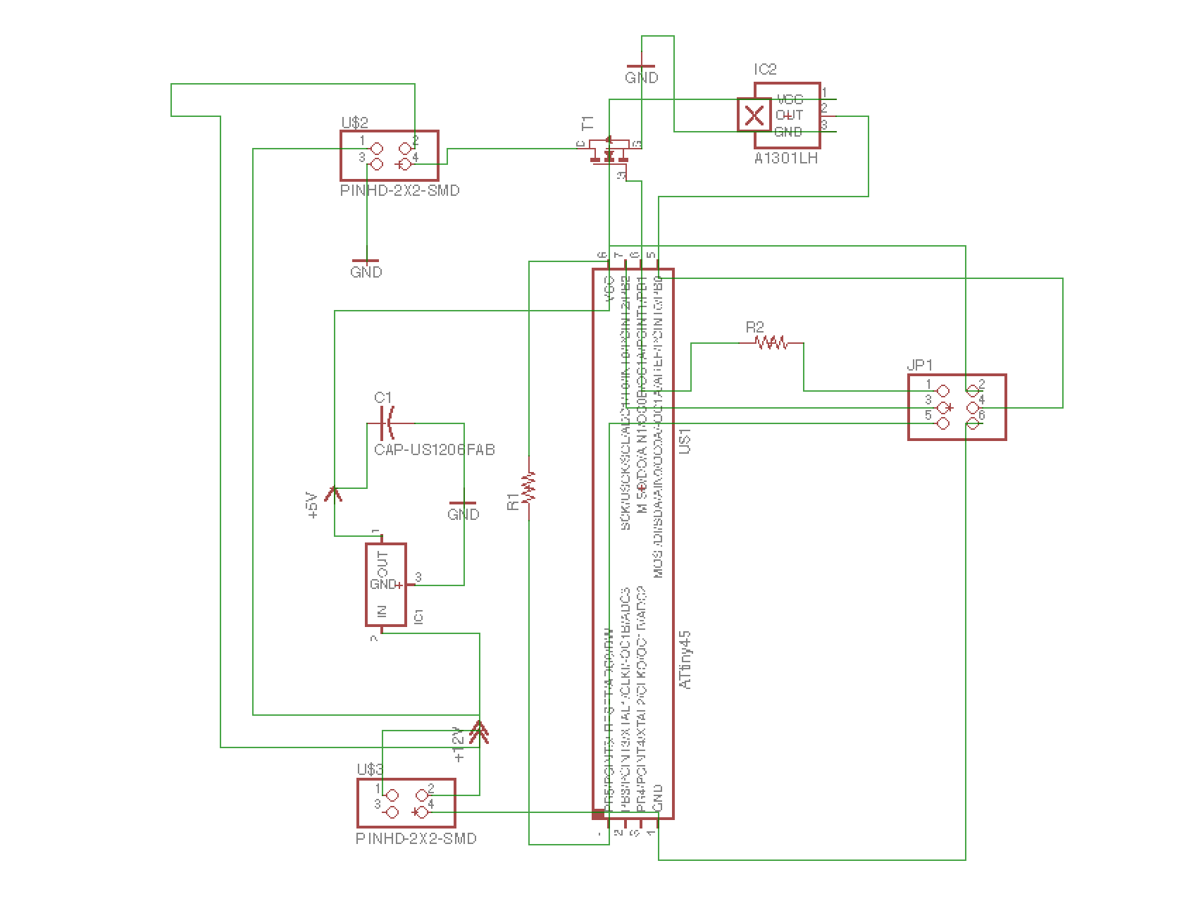
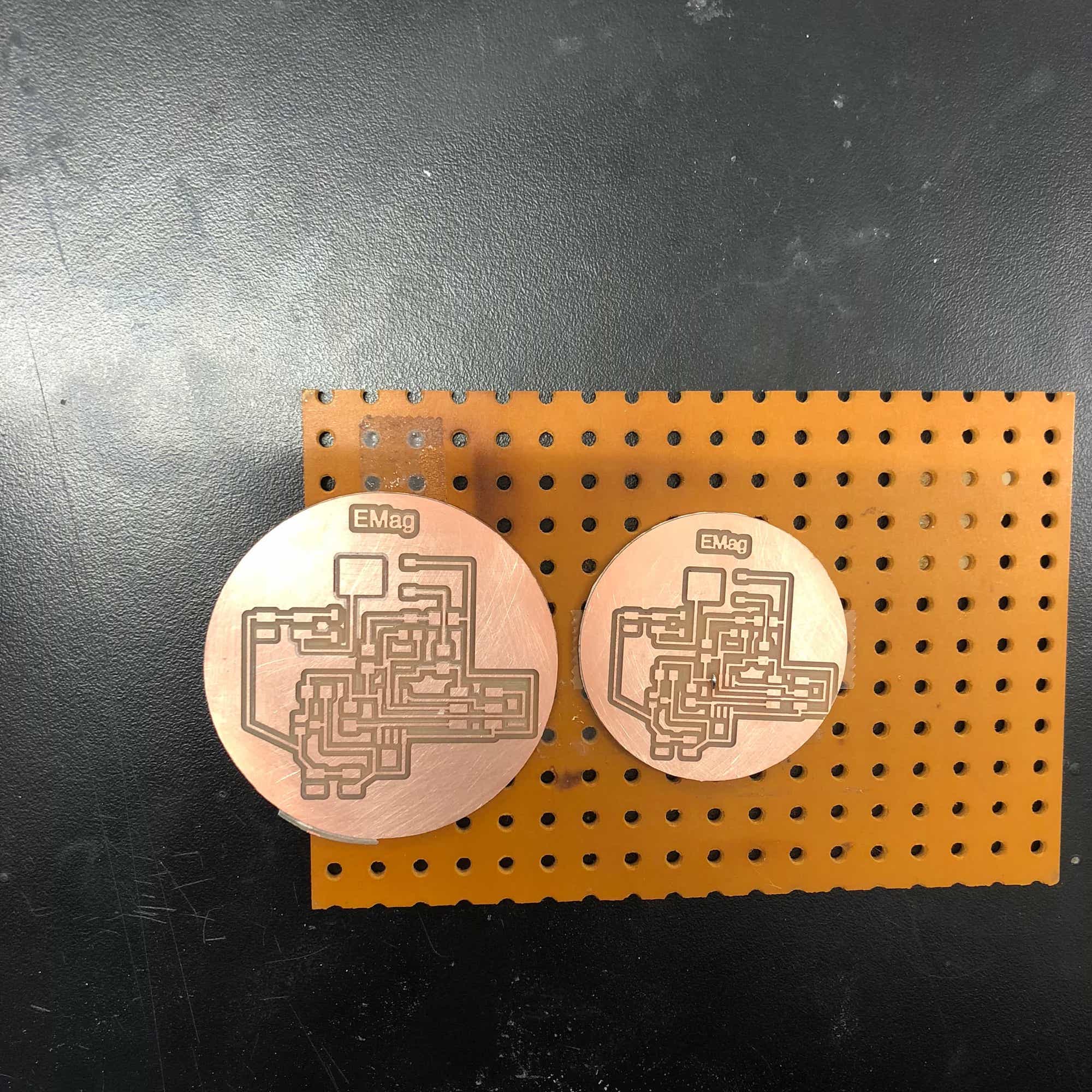
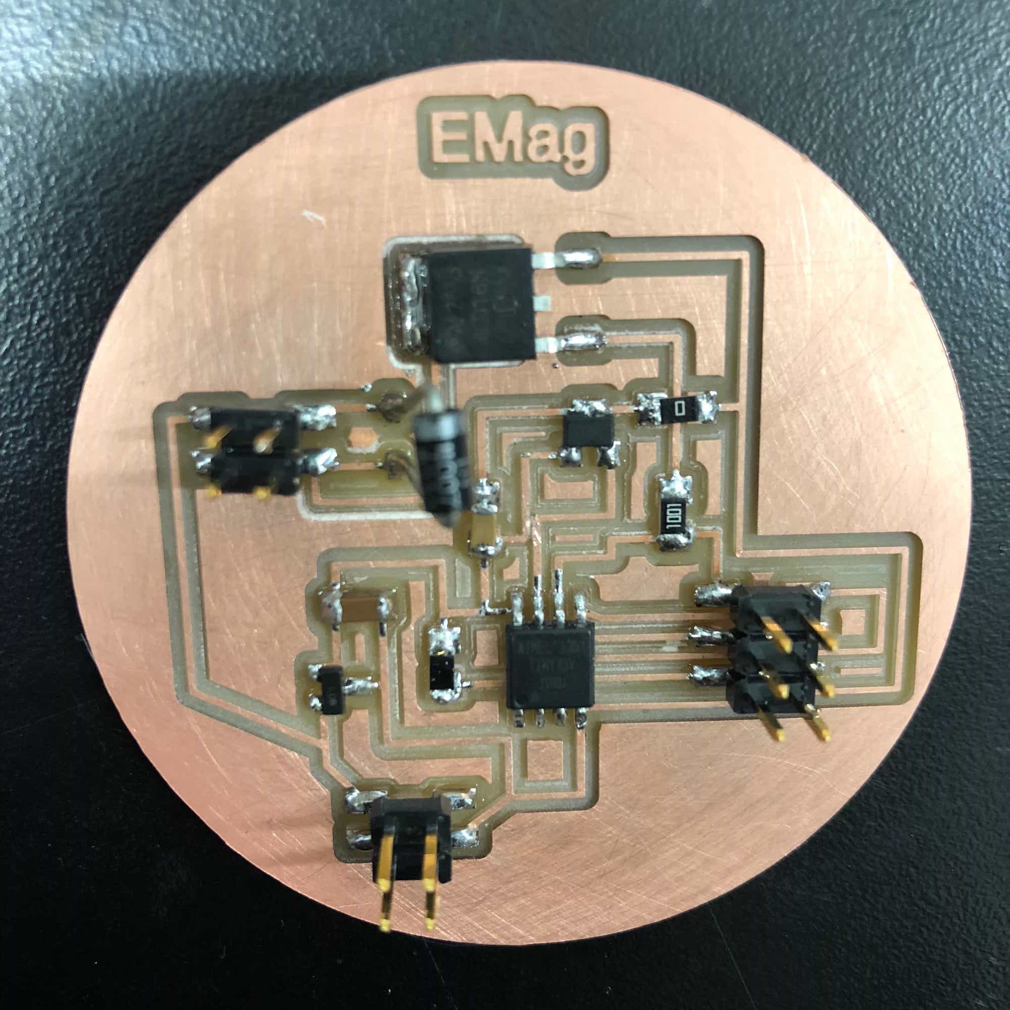
For my cicuit board, I was able to use Neil's design for the speaker and use it for the electromagnet, simply connecting the magnet to the board instead of the speaker. I milled the board using the Roland CNC then soldered the various parts onto it.

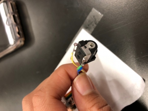
For my power source, I added a ribbon header connected to a 9V wall power adapter, for one of the 2x2 headers. It is important to actually connect this properly so I had to test the connector to make sure power and ground were properly alligned.
The next part was to upload a simple code onto my board that would feed current into the magnet for half a second, then stop for half a second. With a 9V source and 17 Ω resistance, this should be about half an amp of current. How we should see the magnet work is that it will attract a piece of metal on and off, alternating every half second. After uploading the code, this would work for approximately 2 minutes before the MOSFET would die. The MOSFET was set up to handle up to 1.7 Amps so it should have been fine with my setup. I replaced the MOSFET 3 times before enlisting the help of electrical engineering experts, Brian Plancher and Mike from the Electrical Engineering lab at Harvard. Brian realized that we needed to add a diode to the setup to offset all of the back emf that resulted from pulsing the current fully on and off. We connected an LED to the setup and what resulted was that the MOSFET would almost immediately start smoking and die. Stumped, Mike came in to help us figure out that the diode actually needed to be connected with the cathode to the anode not anode to anode. Here are the diagrams he drew to help explain the problem.

As we approached closer to the deadline for our final projects, I had to modify the project so that the object would be suspended from the top, not levitating from the bottom. There is a lot more domecuntation of work done on attractive levitation rather than repulsive. I'll save the repulsive levitation project for a later date.
Final Project Components:
- Electromagnet
- Controlled Current via Microcontroller
- Hall Sensor Inputs
- Program to modulate current for levitation
- Permanent Magnets
- Housing for all the components
The most difficult part of this project, for me, is figuring out a code that will modulate the current source so that object I have is levitated. This will require inputs from the Hall sensor to determine whether the current should be increased or decreased to keep my object suspended.
Components
Making the Electromagnet
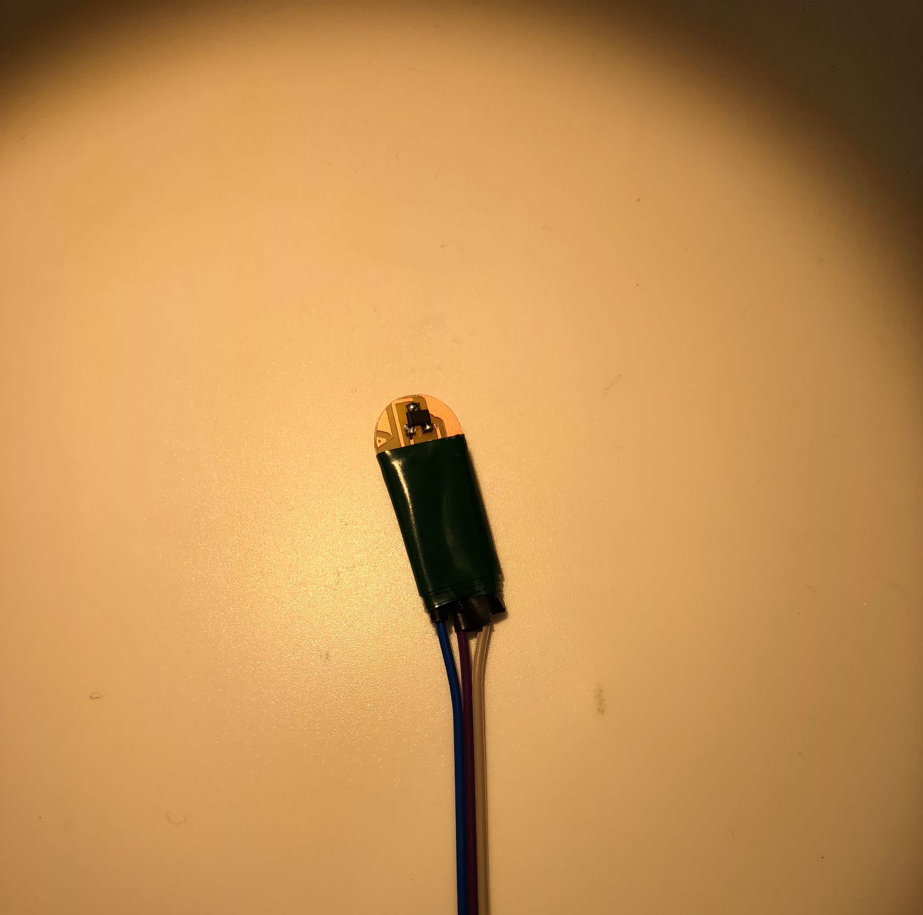
The electromagnet I made for the input devices week was only about 18 Ω. For my final project, I made a new, much stronger magnet. Initially, I designed this spool in Fusion to wind copper around to make my electromagnet
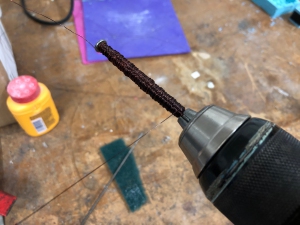
I was planning on 3D printing this and incorporating it for my final design. However, since the 3D printed object would be made of plastic, it would probably lead to a weaker electromagnet. Instead. I used a steel nail, bolts, and washers to create a larger, stronger electromagnet. The resistance of this new magnet is about 50 Ω. This would have taken hours if I had to manually had to wind the electromagnet. Although we did not have an automatic winder in our shop, I was able to use a screwdriver and electric drill to quickly wind my magnet once more. This worked amazingly well and was cool to watch. You just have to be careful with the wire and your fingers since it becomes painful giding the wire up and down the screw. To alleviate this, I used the small red cloth to protect my fingers while I guided the wire.


Components
Magnetic Levitator Frame
For the frame that will hold my electromagnet and showcase the object that I am levitating, I made a simple design on Fusion 360. This was the first time that I used the appearance function to illustrate how my object would actually look like, using the materials I planned to use. I decided on a wooden base with see-through sides, and a wooden top. The appearance function had several finish options and materials. This ended up looking a lot nicer than the standard steel designs that I usually make in Fusion.


I then took my design to the Active Learning labs at Harvard to laser cut it. I used MakerCase to generate a press-fit version of my base. This expidtited the process quite a bit and it made assembling the box a lot easier. I secured the pressfit designs with tiny beads of glue. I used 1/4 inch wood for the box base and the top, and clear acrylic for the sides. I also placed a hole on the top that should be approximately the size of the screw I used to wind my electromagnet around. This way I can easily just bolt my magnet into the frame. The laser cutter was able to cut through all of these without a problem after adjusting the settings to the right material. Here is what the final frame looked like:


Overall, I was ecstatic about how nice the frame came out! Thank you to Steve in the SEAS Active Learning Labs for helping me out with this!
Components
Electronics
Rather than networking my hall sensor board and my elctromagnet board, I created a new board that would both modulate the current through my electromagnet and receive input from the Hall sensor.

I experimented with just connecting my electromagnet to the board and pprogramming a simple code that would turn the current on to power the electromagnet, every 5 seconds

I used the Arduino interface just out of personal preference. This code uses all of Neil's complicated set up for the speaker board but with the main body cut out and replaced with this very simple code.
Once I started to tweak the code to include the hall sensor in the current control, Rob and I realized (after several hours of trouble shooting) that the hall sensor needed to be connencted to an Analog port in order for the microcontroller to get the read. I was able to still use the same board by using an exatoknife to cut the trace and wires to connect my hall sensor. I also took this opportunity to mill a separate tiny board for the hall sensor and connect it to my main board using long wires. I realized that having the hall sensor directly on my board is something that I would not want for my final design since I intend to place the sensor directly under my electromagnet.
After confirming that I could turn the voltage to my electromagnet on and off using the hall sensor and placing a permanent magnet by it, I tried to program the board to actually levitate the magnet. I did this by modifying an Arduino program written for an Arduino or AtMega. The code is pretty simple and will basically just turn the current on when the sensor value falls below a set value, and then turn it off when it is greater than this value. I used the data sheet to convert XMega pins and functions to their Attiny45 equivalent.

After programming my board with this code, an onslaught of problems came my way. Ready to test and see if I could actually levitate a magnet, I connected my board to the 12V power source and my electromagnet. With no permanent magnet by my hall sensor, the current should just be on all the way, however, I had no current going through the magnet because it was not magnetic in the slightest. It could not even pick up a small steel ball. However, a voltmeter revealed that there was still voltage going to my pins. At this point, my board started to smoke and I immediately disconnected everything. Simultaneously, my laptop charger broke???? I'm not sure how these events could be related since nothing else broke but I find it extremely unlikely that it was just coincidence that my board smoked and my laptop charger (which were both plugged in to the same power supply) could have simultaneosly broken. A mystery to be solved later and in the mean time my new charger should be here by the day before the project is due (!!!!).

After this disastrous event, I checked my electromagnet to make sure it was working. I did this by plugging it into a power supply and running about .8 Amps through it. It definitely was working, able to pick up light metal objects. Next, I tried to revive my board. I replaced the Attiny and resoldered some things to make sure my connections were strong. I also replaced the transistor and mosfet. Next, I probed the board with my voltmeter to make sure everything I wanted to be connected was connected and there were no unwanted shorts. I then probed the board again to make sure that the proper voltages were running through each component. I was able to connect to my computer once and I uploaded the code with the simple on/off every 5 seconds. I then went to program it again and the computer could no longer recognize my board. Not wanting to quit on my board, I went in again with my voltmeter. I must have shorted the power supply accidentally while I was doing this because more smoke than I had ever seen from a circuit board came out, burnt my finger, and melted the wire protection on the wires that lead to my power supply. Terrifying and probably destroyed my board beyond repair. Despite knowing that several things would probably not be working. I still attempted to rescue my board by probing and replacing the microcontroller. A key lesson I've learned from the endless hours I've been spending in lab is that I need to stop wasting several hours trying to fix or save my board. I would probably save a ton of time and get to practice my soldering skills by simply milling a new board. These disasters happened around midnight and at that point I called it a night.
The next morning, I headed to the electrical engineering lab at Harvard to see if I could enlist the help of experts. In the electronics shop, Mike Litchfield sat down with me for more than 4 hours straight to figure out why I kept having issue with my board smoking, etc. After connecting the circuit to an oscilloscope, we saw that even with the flyback diode, there were still about 150V spikes. Mike walked me through a lot of math and physics to explain how this relates to the time constant and that the diode was not quick enough to prevent the back emf spikes.
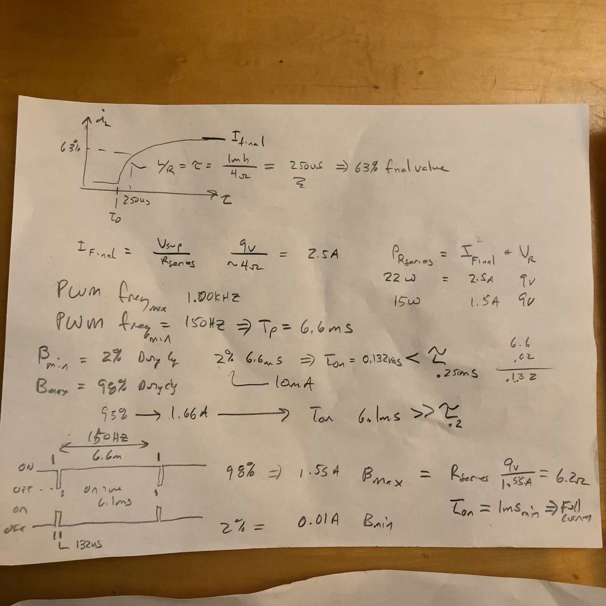
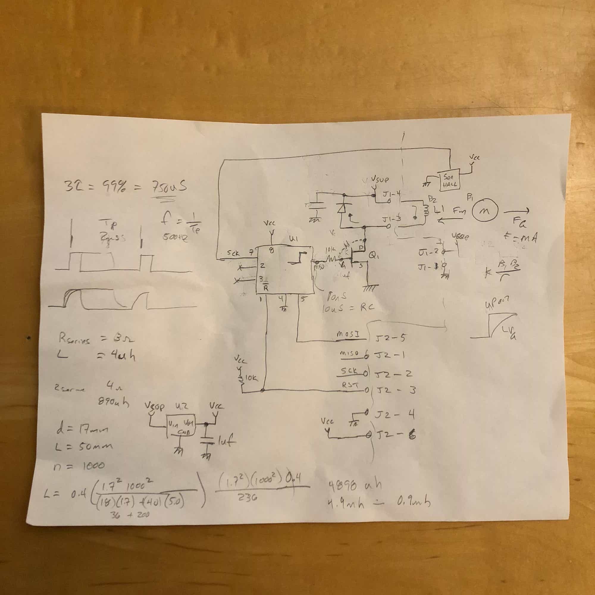
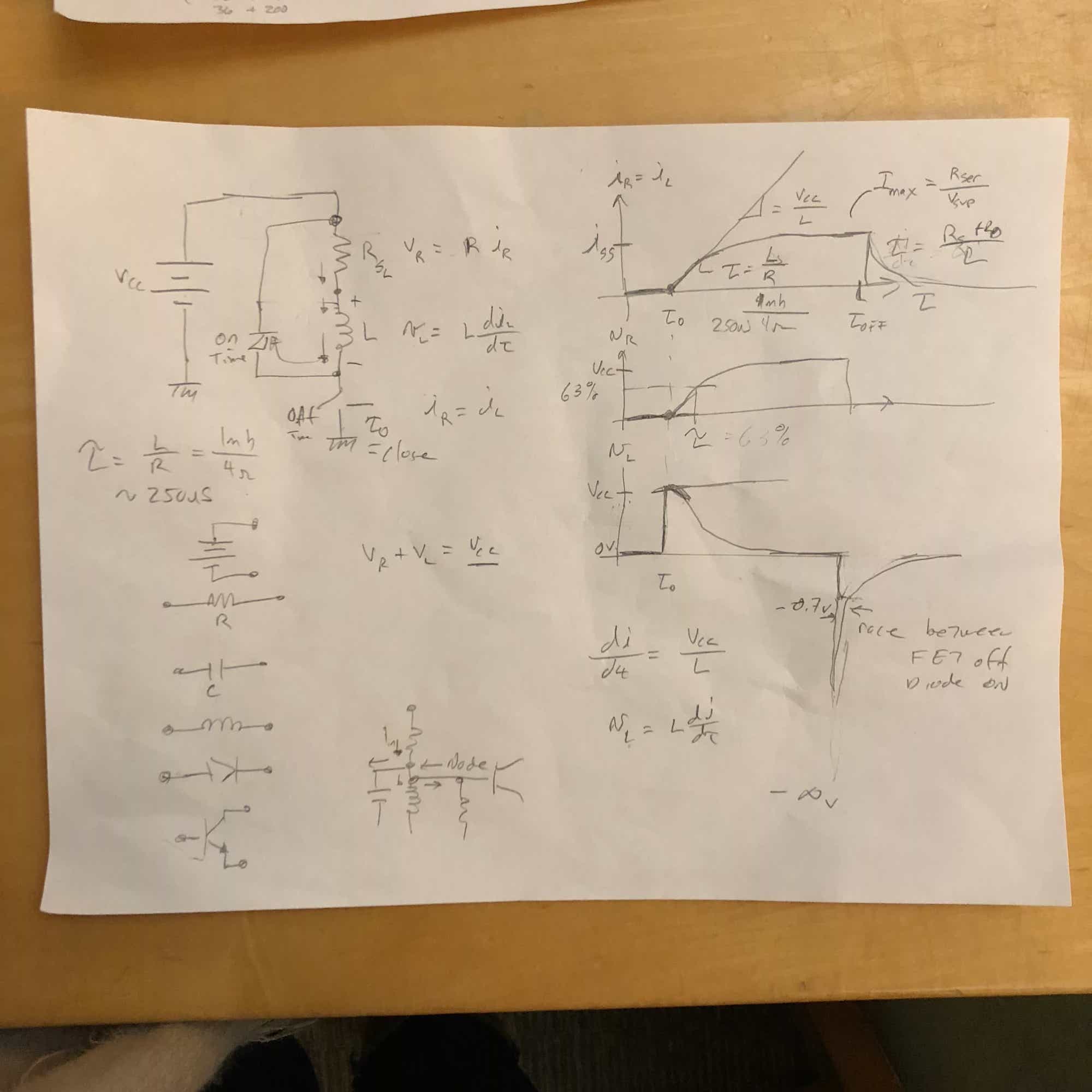
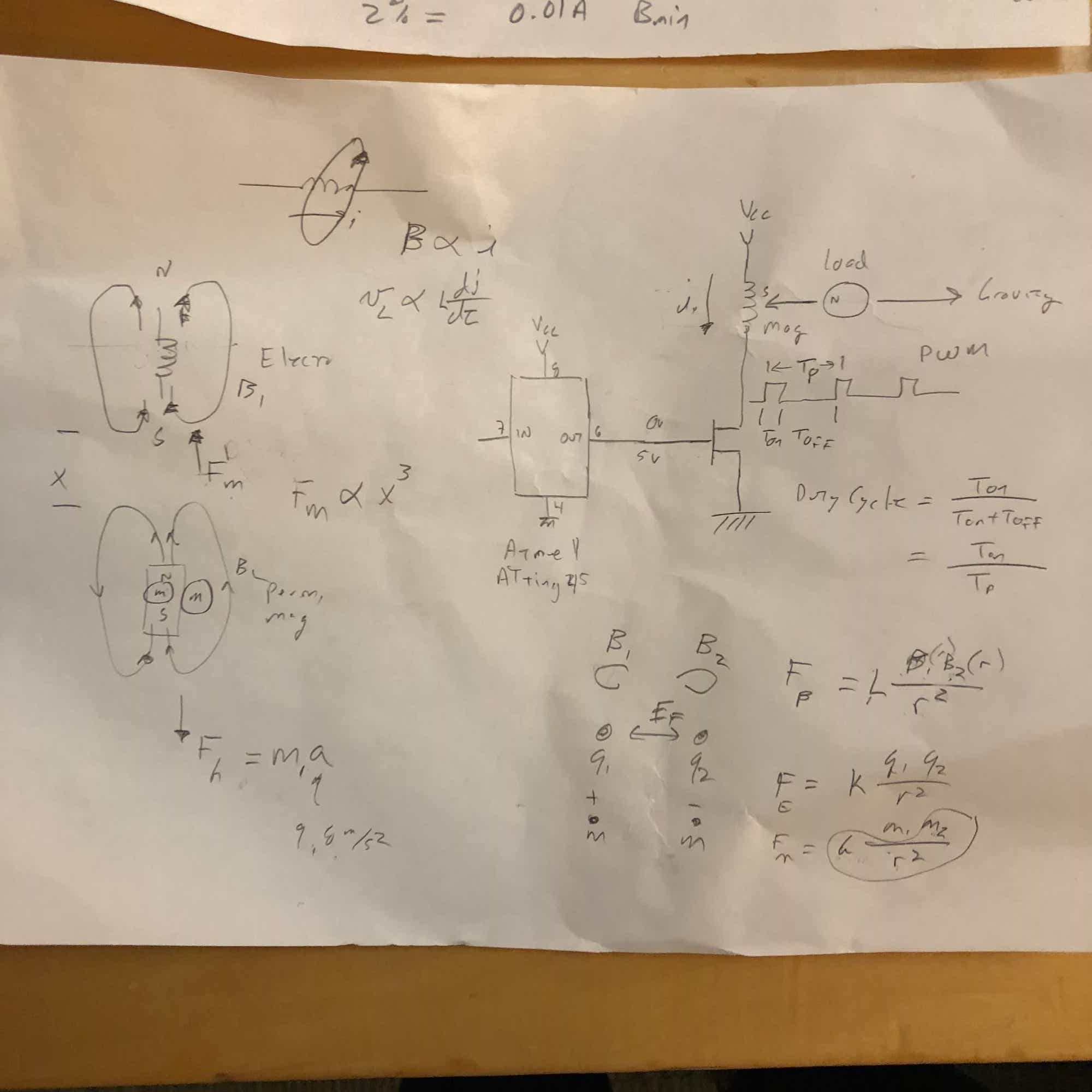
Professor Paul Horowitz was also in the lab and helped with figuring out how to deal with the voltage spikes in my circuit. He pulled out his textbook, the Art of Electronics, to explain that we needed to add a resistor across my microcontroller and mosfet because of something called the Miller effect. We checked this on the scope and sure enough it worked.
The conclusion:
- Keep the diode
- Add a resistor between my microcontroller and the MOSFET
- Think about time constants and component speeds
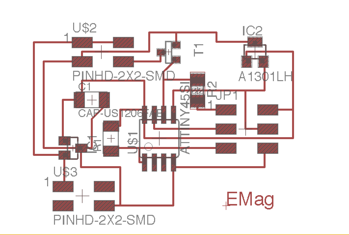
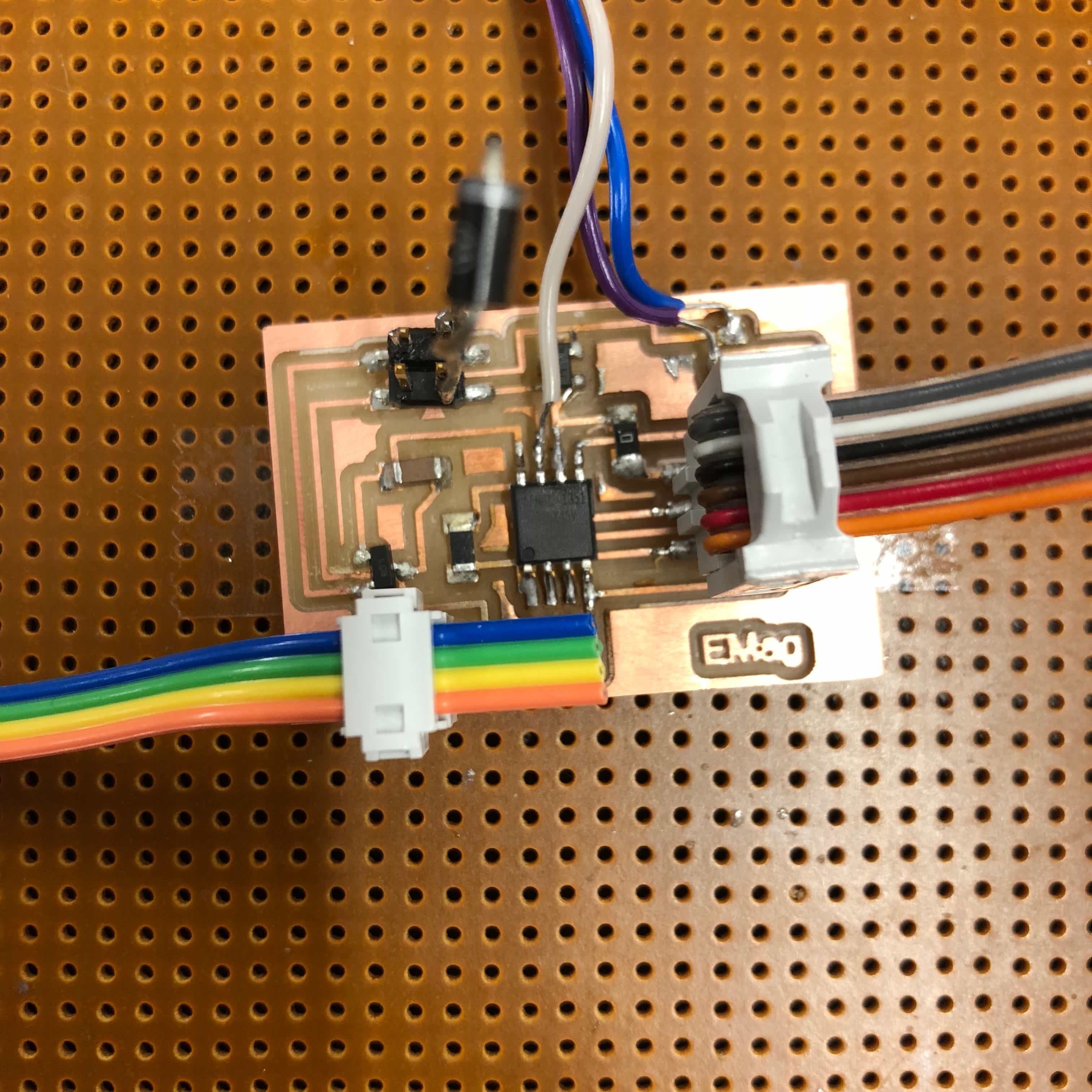
I designed a new circuit board that included the resistor between my MOSFET gate and microcontroller.


What I learned while milling this board is that I can't just choose any number for what I set my dpi to. There's been a system for Macs where we export it at 1000 dpi but then double it to 2000 when we get to mods. This usually adjusts the board to a size that fits on our precut 2 by 1.5 inch copper boards. However, this piece was just slightly to big so I increased the dpi to 2500. I thought it had come out fine but when I went to solder the components on, the pads and area for the microcontroller, in fact all components, was too small. I was able to find a 4x4 inch copper board and remilled the full size 2000 dpi board onto it.
After milling and stuffing the board, I programmed the board to first just turn on and off every 5 seconds. It worked and did not kill my board so I proceeded with trying to run the code that should, in theory, levitate a permanent magnet. Just for testing purposes, I fastened the hall sensor onto the bottom of the magnet with just a double sided piece of tape.

To my great dissapointment, my maglev was still not levitating anything. I contacted Yuval, an EE and computer scientist TA, to see if he could help me to figure out how to get my magnet to work and to read over the code and make sure that the logic made sense. He agreed that code was pretty straightforward and should work. We hooked up the board to the oscilloscope to see how the hall sensor was interacting with the board and how the board converted those inputs into commands into the rest of the system. The wave patterns showed us that our code seemed to be working in the way we intended it to. The voltage was high when there was magnet near it, then dropped to zero when the magnet became too close. It also demonstrated that it was performing the in between function because we could see points where the current was turned on somewhere between 0 and high. Next, we checked my electromagnet to make sure that it was working properly, We hooked it up to a power source and gradually increased the voltage. What we found is that it only takes about .8 volts to get my magnet to stick a tiny steel ball but that at 12V, the magnet was still pretty weak and could not pick up larger steel balls. We wanted to test how strong we could get the magnet to be so we raised the voltage up to 20V. The electromagnet at this point started to smoke quite a bit. It was extremely hot and remained like that for a while. We turned the voltage down and came to the conclusion that I had a very weak elctromagnet. Our hypthesis was that because the electromagnet was so weak, the margin between where a permanent magnet levitates and where it falls or attracts all the way up, is too small for us to find. It would be great if there were a for loop that could run through a bunch of values for the levitation point and find which one worked. Unfortunately, you had to reprogram and test the board for every new number we tested. With only a day left to work on my project, we decided that it was time I started to get plan B of my project done.
Plan B: Magnet activated Electromagnet
Knowing that there was a big chance my magnetic levitation project could fail, I've been thinking a lot about a back up project that still used all the same concepts and components but did not require such fine tuning. I could use the hall sensor as a switch to turn my electromagnet on and off. I did this by writing a fairly simple code that would turn on the voltage to my electromagnet all the way on when the voltage the hall sensor output was greater than 2.4 volts. If it was less than this, it would be off. I used 2.4 becuase this is the value that the voltmeter reads from the hall sensor when there is no magnets near it. I converted the resolution value to voltage by dividing it by 1024 and multiplying it by (2.4/5). I used 2.4 because it is my target voltage and 5 because that is the maximum voltage to my microcontroller.

After loading the new code onto my board, it was time for the moment of truth when I would test to see if it could do this much simpler prgram where it only had to turn on and off and not worry about balancing. Fortunately, it did! I was able to pick objects up by placing a magnet in the proper orientation near my sensor. I ended up rewinding my electromganet as well, just to make sure it was functioning. I ended up using a 9V power source with a 2.77A tolerance.
The Final Result
Magnet from April Johnson on Vimeo.
Final Results
Implications
With the remaining time I had left, I tried a last ditch effort to go and talk to an EE in the Active Learning Labs who I heard had made a maglev in the past. I met with Evan Smith, who had made a maglev as a group project during his undergrad for EE. It had taken the group about 2/3 of the semester to get this project done. Evan was a wealth of knowledge able to share mistakes he made when doing the project. Two things that could help make finding the setpoint easier is creating a shelf directly below my electromagnet where I could encase my hall sensor and buying the electromagnet online so that I knew it would definitely be strong enough. This way it was guaranteed to be centered, stable, and consistent. When we return from winter break, I plan to keep working on the project to have it ready in time for the Harvard Open House at the end of January.
Because I did not have to buy any parts and only used a small bit of cheap wood and acrylic to make the frame, I would estimate the cost of this project to be under 10$!