Output Devices
Electromagnet
The assignment for this week was to take our circuit boards and have it connect to an output device and program it to make the device do something. This week, I finally started working towards my final project. I have changed my project from the CO2 sensor to basically prototyping a hoverboard. Not one of those hoverboards that rolls around on the ground that took over the world in 2015 and 2016, but a real, Back-to-the-Future type hoverboard.

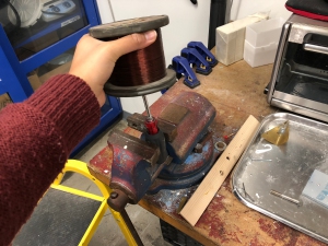
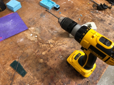
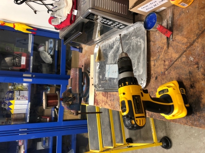
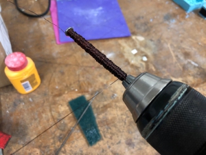
By winding coil around steel and running current through it, you can create an electromagenet. The first step was to wind my magnet. The magenet is strengthened by a factor of N, the number of turns around the coil, and weakend by a factor of 1/l, the length of the magnet. Since hand winding is inefficient and would take a long time to get a lot of turns, Rob in the Harvard shop helped me to make a setup where I used a screwdriver, clamp, and electric drill to make a homemade coil winder. The end result was an electromagnet with about 17 Ω resistance.
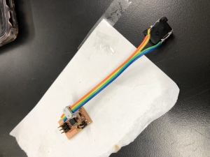
For my cicuit board, I was able to use Neil's design for the speaker and use it for the electromagnet, simply connecting the magnet to the board instead of the speaker. I milled the board using the Roland CNC then soldered the various parts onto it.

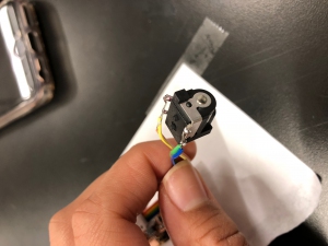
For my power source, I added a ribbon header connected to a 9V wall power adapter, for one of the 2x2 headers. It is important to actually connect this properly so I had to test the connector to make sure power and ground were properly alligned.
The next part was to upload a simple code onto my board that would feed current into the magnet for half a second, then stop for half a second. With a 9V source and 17 Ω resistance, this should be about half an amp of current. How we should see the magnet work is that it will attract a piece of metal on and off, alternating every half second. After uploading the code, this would work for approximately 2 minutes before the MOSFET would die. The MOSFET was set up to handle up to 1.7 Amps so it should have been fine with my setup. I replaced the MOSFET 3 times before enlisting the help of electrical engineering experts, Brian Plancher and Mike from the Electrical Engineering lab at Harvard. Brian realized that we needed to add a diode to the setup to offset all of the back emf that resulted from pulsing the current fully on and off. We connected an LED to the setup and what resulted was that the MOSFET would almost immediately start smoking and die. Stumped, Mike came in to help us figure out that the diode actually needed to be connected with the cathode to the anode not anode to anode. Here are the diagrams he drew to help explain the problem.
