
Electronic Prodution
Printed Circuit Board
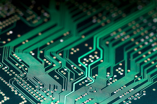
This week we are working on making a printed circuit board. With help from Rob and Dixon, this was relatively painless, almost relaxing, process. The first step in producing our PCB was to go into a small room adjacent to the SC102 lab to print the traces and cut out a blank board. The machine I used was the Roland SRM-20.

I cleaned the plaform of the machine by scraping off any leftover tape residue. I then secured a PCB blank onto the platform using double sided tape. The blank consistst of a plastic base with an insulating top layer, copper. I uploaded the traces and ran it through the platform on the website for a 1/64 inch setting. First, I had to set the origin point for the machine as close to the corner of the blank plate as possible. Once the x and y axis were set, and the z was relatively close to the surface, I unscrewed the millend and lowered it so that it was actually resting on the board.I ran the machine to begin the cuts. Rob quickly noticed that the machine ws not cutting deep enough into the board.

When the machine is cutting at the depth you want it to, a bit of the plastic sublayer comes up in the form of white dust. We stopped the machine and sent the top back to the origin. I unscrewed the millend again and applied gentle pressure downwards so that the millend was pressing down on the blank board. This rescued the milling and we were able to restart the program using the same piece of board. It simply retraced over the parts it had already done. There was a noticeable difference between this setting and the previous one. You could clearly see the white dust, indicating that the mill was cutting all the way through the copper.

After cutting the traces, I changed the endmill to the 1/32 inch one and loaded the outline onto the program. Learning from last time, I pulled the endmill down so that it was applying slight pressure onto the board. You could tell the difference between this cut and the trace cut because there was substantially more dust. After this process, we were left with the cut board.

We brought the PCB to SC 102 for soldering. I gathered all the components and taped them onto a white paper to keep all the small parts together. This was also a great way to keep track of what each piece was, for someone who is not familiar with the electronic components.

Dixon ran me through the art of soldering. It is key to heat the board first, keep the soldering iron clean, and make sure the components are actually soldered on. Often times (especially in my case) the component was just resting on the solder and not actually attached to the board. The solder is a filler metal that melts at a low temperature so that it can connect other metals together. This connection allows the current to pass through the board. Each of these electronic components have a metal strip or metal in some form. This is key in making sure that the board actually works.

I ran into a problem later when trying to code my board, that the metal piece had actually fallen off the component and so the board was not working. In order to fix this issue, I remelted the solder and removed the part with the tweezers. I got a new piece and made sure to solder it flat to the board. Another issue I ran into was creating the bridge that connects the V(cc) to the V(prog). This is done so that the header can be used to program the tiny45. When I had not done this and tried to program the tiny45, the computer failed to detect a USB. After soldering all the components onto the board, I was able to plug the USB into the computer to program it. The lights on the board indicated it was working.

Once the chip was programmed, we reset the pin to enable it to program other boards but halting its ability to be programmed. The final step was breaking the bridge connection of solder. Here is the completed PCB!
