Electronics Production
Electronic Design Automation
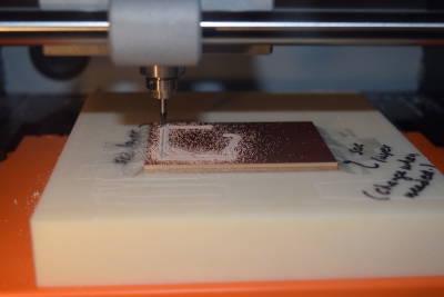
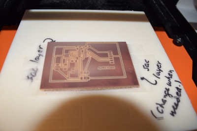
For week 5, the first assignment is to redraw the echo hello-world board and add at least a button and LED with current limititng resistor. After designing the board, we then need to go though much of the steps we went through in week 3, with printing the board and then testing it. This week gives us a chance to learn more about electronics and also to practice soldering a bit more. For this week, Neil intorduced the basic physics that goes into making the board and actually having it work. This actually conincides nicely with my other class, Physics 12B: Electromagnitism and Electricity, as we are learning about Capacitors, Resistors, Ohm's Law and Kirchhoff's Rules. For designing these circuit boards, there are basic rules thay you need to follow. The largest learning curve for me will be in figuring out how each of these components connect with each other.
The program I used to design the circuit board is Eagle. This is a popular and free software that has been bought by the Autodesk suite. First, you need to upload all of the fab parts into Eagle. This folder will have all of the components that we will need to make the board.
Board Components
- 10k Ω Resistor
- 100 Ω Resistor
- 0 Ω Resistor
- 1 μF Capacitor
- Attiny44 Microcontroller
- LED
- J2- FTDI
- J1- ISP
- Button
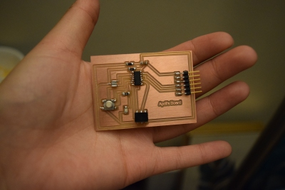
Most of these parts are derived from the echo hello world board with the addition of a button, LED, and 0 Ω resistor which I added as a jumper.