Week 1: Laser and Vinyl cutting
Group Assignment: “Characterize your laser cutter, making test part(s) that vary cutting settings and dimensions”
We (Zijun, Elena, Teja, Ravi and Yousef) characterized the tolerance for laser cutting using the GCC machine and found the proper cutting parameters (mainly speed and power) for cutting cardboard. We decided to test a few different parameters and settings during our test cuts: First, we tested the difference in planned widths and actual widths of cuts for slots that could fit the width of a piece of cardboard. We chose to do this in preparation for the individual assignment (the press-kit construction). First, we measured the thickness of our cardboard to be 0.165inches (approx 4.19mm) using calipers we found in the lab. We then sketched (in Fusion 360 and Solidworks so that a few of us could play with design) a rectangle with cutouts of 4mm, 4.25mm, 4.5mm, 4.75mm, and 5mm in width and 20mm in length. Additionally, we decided to raster cut the settings for the power, speed, and ppi for both the vector and the raster cuts. For this first cut, the settings were: Raster (R): 50p, 50s, 200ppi Vector (V): 100p, 3s, 200ppi. We ran a test print with the lid up so that we could determine whether the cardboard cut out we were using was in the right position.
We would like to find out the proper width of the slot for a part made of this cardboard can fit in, not too loose and not too tight. We first measured the thickness of the cardboard we are going to cut using a caliper. The value is 4.19mm. Prof. Gershenfeld suggested changing the parameter at a step of 1mil ( 1/1000 of an inch, or about 25um, 25.4 to be exact). Since cardboard is prone to material burning, we chose a larger step size, of 250um, and started with the following range: 4.00mm, 4.25mm, 4.50mm, 4.75mm, 5.00mm. It seemed that the 4mm is a bit tight and the cardboard gets bent and above 4.25mm the joint is a bit loose. After doing a second round of test (50um increment from 3.9mm to 4.25mm), we found the desirable range of slot width to be between 4.00mm to 4.15mm.
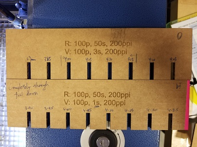
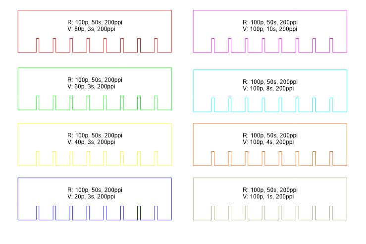
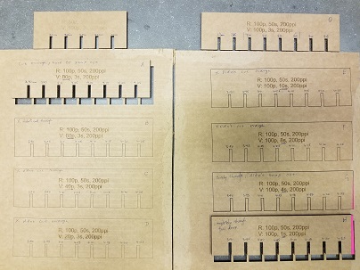
We also did some laser-cutter parameter tests, varying the speed and power. This enabled us to compare different power and speed settings as outlined below. We kept the slots as set previously so that we would not need to change the design in CAD. It seems that for 3% speed of the GCC machine, the power should be above 60% for a successful vector cut. And for 100% power the speed should be below 4s. We also increased the power of the raster cut so that the etched settings would be more visible on our print out.During this print, we noticed that the more powerful rester cut left a clearer etch on the cardboard.
Individual Assignment
Vinyl cutting
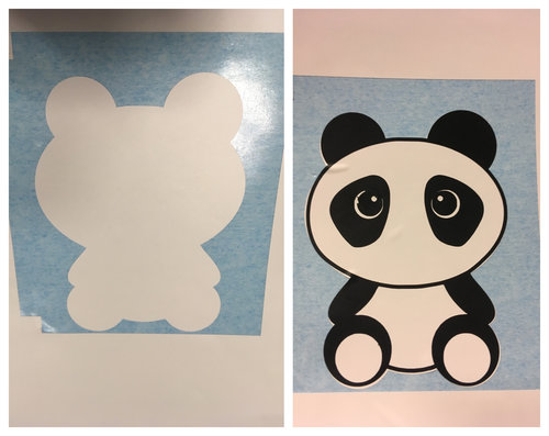
For this particular assignment, I wanted to make a cool panda sticker for my macbook. I downloaded a free image online (.jpg) of a panda from pixabay (the image below). Then, I used online converter convertio.co to convert from .jpg to .dxf and .svg. I edited the image accordingly using coreldraw as some of the features were missing because of the conversion. Then I rescaled of the image without changing the aspect ratio to 100mmx114mm. I made two separate drawings one for white layer and another for black layer with alignments to align them after vinyl cut.

Intially, I thought I will complete the task by stacking two layers black colored one on top of white, I made designs accordingly. As shown in the following image, I used tweezers to peel off the extras, I got the white layer one correct. Nose and mounth part of panda got removed while I was peeling off the unnessary parts in the black layer which resulted in the following sticker without nose and mouth after I stacked the black on white using a transfer paper.
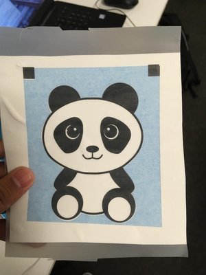
I recut the black layer and peeled it off carefully using tweezers. I could succesfully retain the nose and mounth parts. Here is the image of the sticker after stacking and aligning three layers.
Laser Cutting Assignment
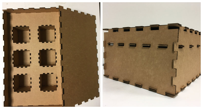
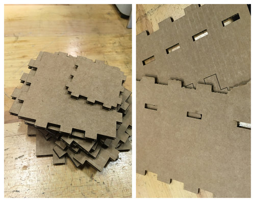
I wanted to fabrciate the cardboard version of Lab-in-a-box for this assignment using press fit technique. The box should be able to accommodate 6 modules/tools. The box consists of six faces and one hanging structure inside, supported by the sides, which consists of six module holders. I designed the cad files cad files using solidworks student version. I optimized the lasercut (GCC Lasercutter) settings to Speed:3% Power:100% and PPI:200 for a good cut. After multiple failures of press fits (Image below), I optimized the parameters. The slots need to be 1mm smaller in legth for a good joint. For longer parts I kept a difference of 1mm and for shorter parts, I kept the difference to 0.5mm
Once I optimized the lasercut and press fit parameters, I could easily fit faces of the box and the modules as shown below
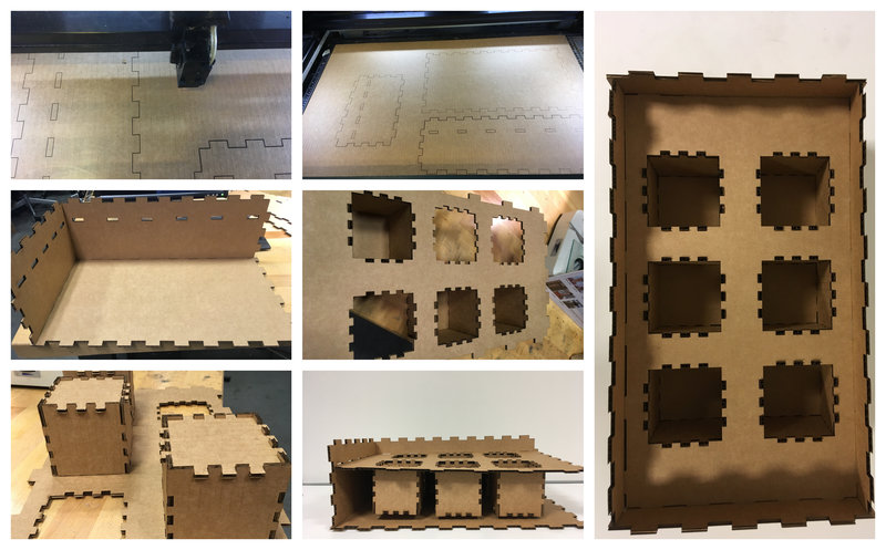
This is the final image of full pressfitted box