Week 4: Electronics Design
This week we had to program Hello world board and add an LED as output and Switch as input to the microcontroller. I used Autodesk eagle to design my schematic and board.
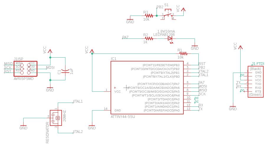
Here is the Eagle Schematic I made [I came to know when I was doing embedded programming that the pin I used for the push button switch was not the correct one]. Please refer to Week6.
Components used to design the board:
1x 6-pin FTDI header
1x 6-pin ISP header
1x 20MHz resonater
1x SMD button
2x 10k ohm resistor
1x 1k ohm resistor
1x red SMD LED
1x 1uF capacitor
1x ATtiny44
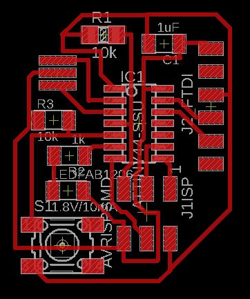
I used 16mil as my trace width and clearance width while routing. I tried using autorouter, but it suggested me milling a double sided board which will have components on both sides of the board [double layered]. I used Hello world board as a reference to route my traces. I could quickly route my board without any conflicts. Here is the board!
I used the following commands to export the file:
1. Perform DRC check to see if they are any errors.
2. Type “display none top” in the command line, to get the top layer with traces only.
3. Export the image from FILE, to .png. Make sure you choose Monochrome and 1000 dpi.
4. Type “display none dim” in the command line, to get the outline and similary export it into .png like the one for traces!
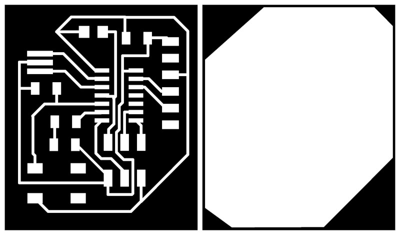
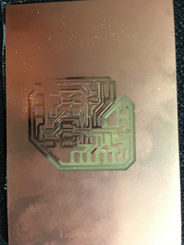
Here is the board, traces and outline for my board. The Milling Machine Roland Modela MDX-20 mills the black parts of the image as per the directions of mods software.
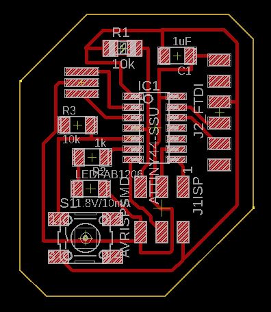
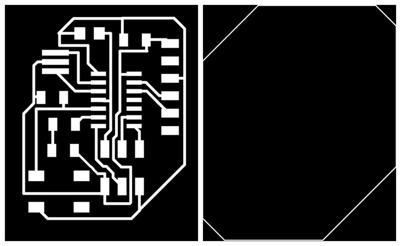
For the outline the inside of the board must be white and the outline in black. I used GIMP to invert the image.
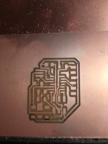
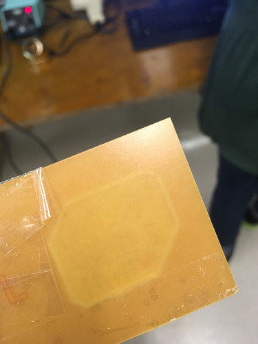
Here are the traces after milling. They didn't come out good as expected. This might be because the board if not flat.
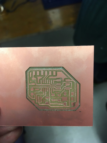
I repeated the milling process this time I made sure the board if flat.
But, to my surprise the outline wasn't cut properly! This is because the tool holder is lowered to it's maximum limit to cut the outline. Usually it take three rounds of cut to cut through the thickness of the board by moving in z-direction in discrete steops. Since the tool head is lowered to its maximum possible limit, it couldn't move further down and it couldn't cut the board.
One more failure!
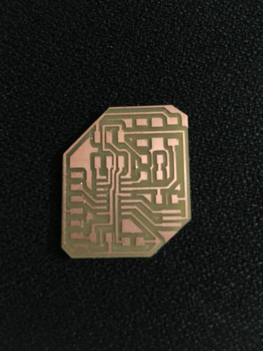
This time it came out well.
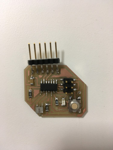
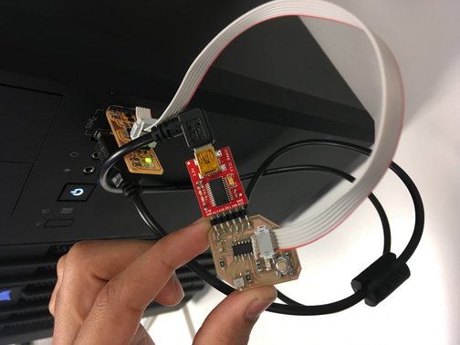
Here is the soldered Hello world board
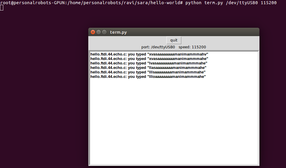
I used my USP tiny I made in week2 to program my hello world board using the commands described here. Here are the screenshots of the process.
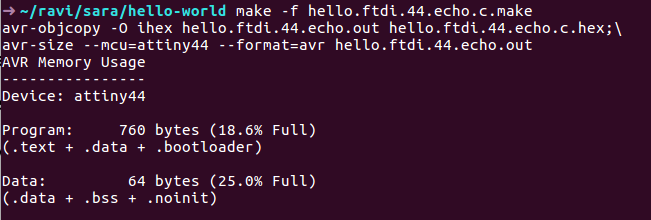
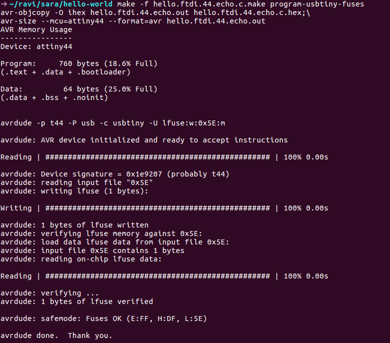
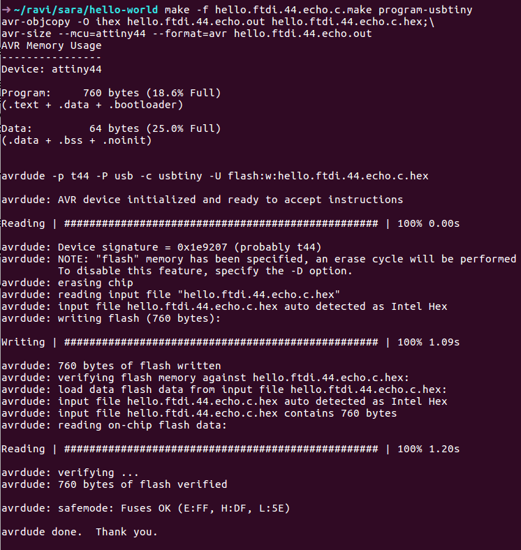
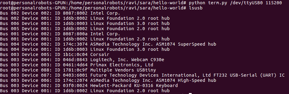
It worked fine!!!