
Week 8: Input Devices
For Input Devices week, the objective was to add an input sensor to a microcontroller and read input from the sensor. I wanted to start with Prof. Gershenfeld's thermistor sensor board NTC Thermistor board. The circuit was designed to measure temperature of an object using a NTC thermistor. I wanted to modify the existing design by adding one more thermistor and so that I can measure the difference between the temperature of two objects.
First I reproduced Prof. Gershenfeld's board as following
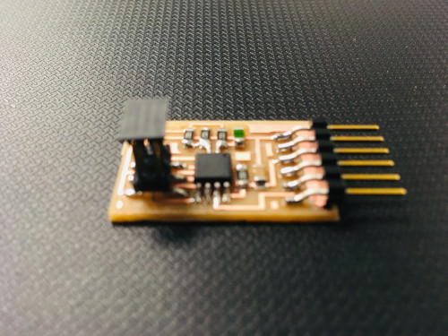
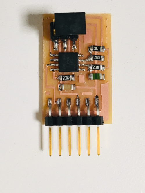
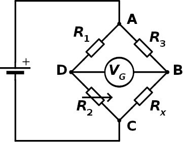
This board consists of a wheatstone bridge. Wheatstone bridge can be used to measure the resistance of the resistor that's unknown. The wheatstone bridge shown here has fixed value resistors R1, R3, a variable resistor R2 and an unknown resistance Rx. One can find the value of the resistance of Rx by varying the R2 value such that Voltage drop between B and D is zero. Then the resistance can be calculated as Rx/R3=R2/R1. We can use the wheatstone bridge with three fixed resistances and an unknown resistance as explained here. In this case R2 is also fixed and we will need to measure the voltage drop between B and D which is not zero anymore.
The resistance of the NTC thermistor changes with the temperature. By finding it's resistance using a wheatstone bridge with three fixed resistors and by measuring the volatge drop using ADC pins (PB3 and PB4) of a microcontroller such as attiny45, we can estimate the temperature.
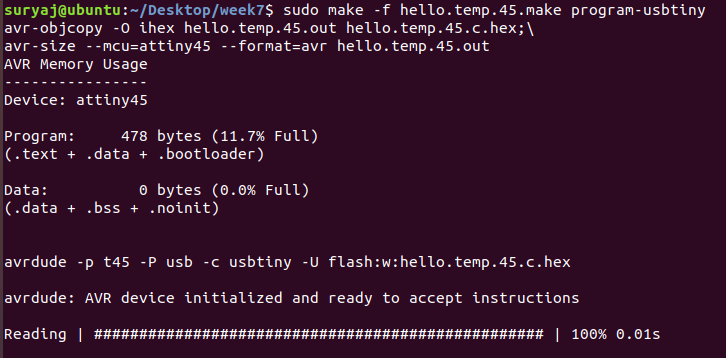
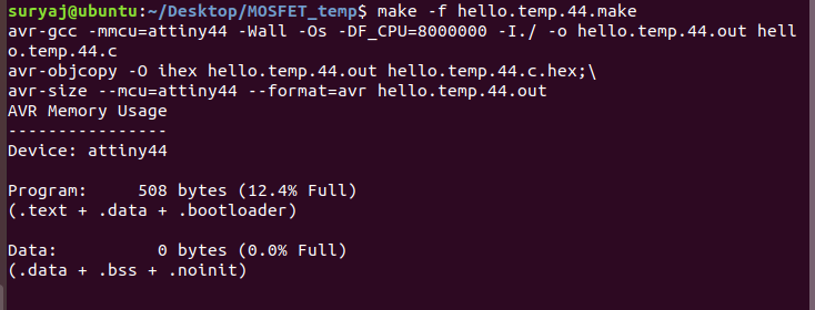
I used hello.temp.45.c, hello.temp.45.make, hello.temp.45.py of Neil to compile the board and measure the temperature. Here are the steps I followed while compiling the microcontroller.
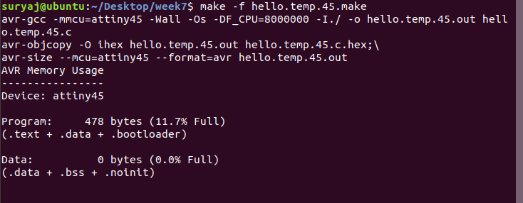
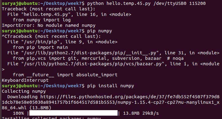
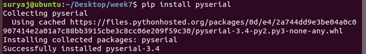
Although the programming of board went fine, the python interface didn't show up as expected. I needed to install numpy and pyserial using pip as shown.

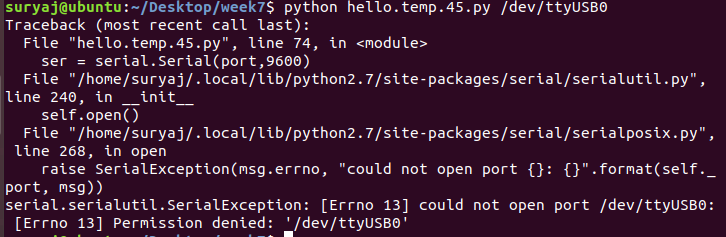
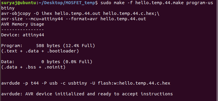
I came across permission denied error which I had no clue how to resolve. Then after struggling with it a couple of hours, Ravi asked me to use sudo infront of the command and it worked!
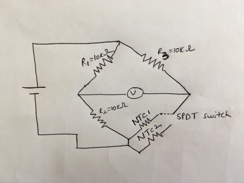
To accomplish my objective which is to measure the temperature difference between two objects using two thermistors, I can use two wheatstone bridges and use a different microcontroller with more pins. But I want to use only one wheatstone bridge and measure the difference using two thermistors. I came up with the following circuit which uses one wheatstone bridge, two thermistors and one SPDT switch. If I use this circuit, I cannot measure the temperature difference simultaneously. I have to control the SPDT switch manually. This introduces time lag.
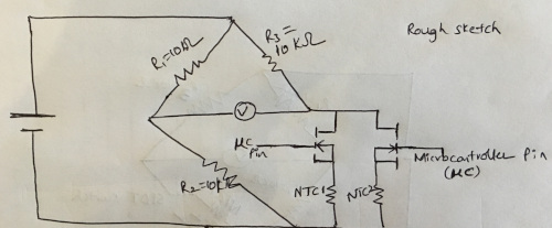
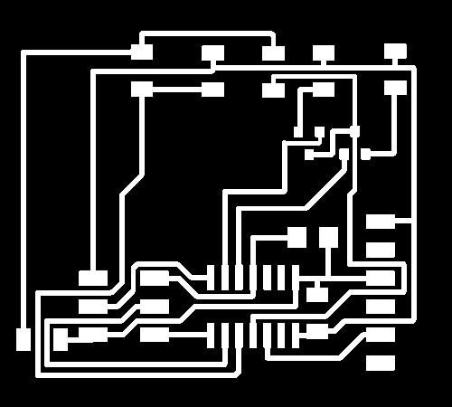
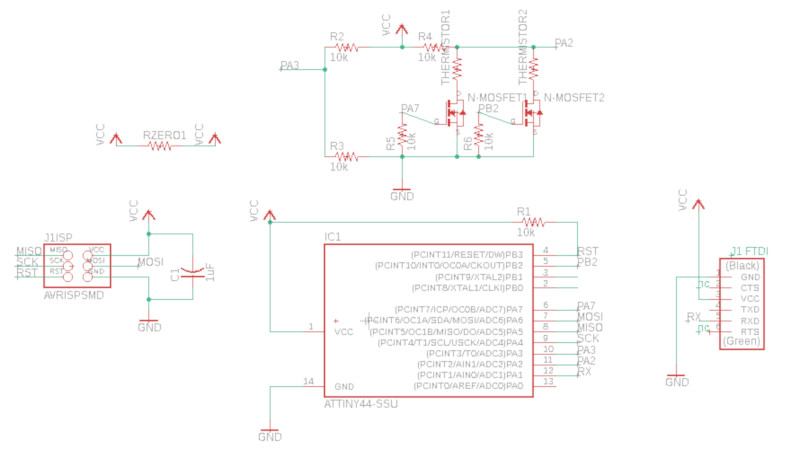
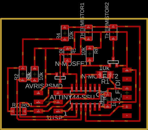
I started searching for high speed switches, then I realized I can use transistors. I used BJT transistors in the previous assignments, I never used MOSFETS. Thomas also suggested me to use MOSFETS for switching these circuits. Using a MOSFET which can be controlled by microcontroller, I can do high speed switching!!! Here is the circuit I came up with.
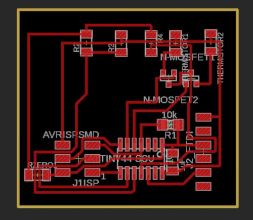
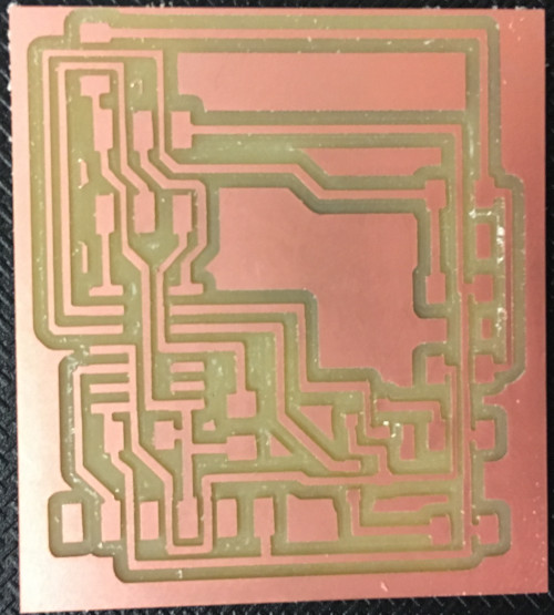
I used Autodesk eagle to make the schematic and Roland Milling Machine to mill the board. I soldered the components as shown below.
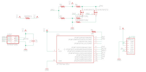

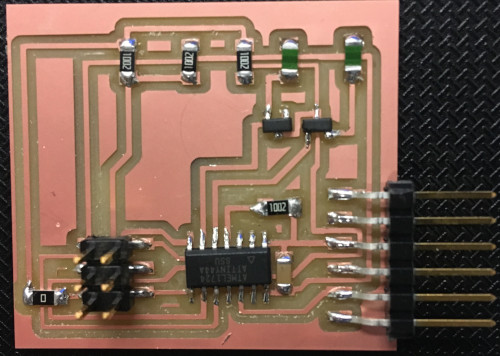
I could compile this board. I couldn't read the voltage from the wheatstone bridge using ADC pins. I wasn't sure if it was because of MOSFETS or my code. I tried to troubleshoot my device by using a multimeter to check mosfets are working. I could see the microcontroller pins connected to MOSFETS are working properly. They are outputting 5V to the gate of mosfet. It isn't clear for me if the mosfet is acting as switch even though the voltage at the Gate is 5V. This is because I designed the board such that the load (themistor) is between Source and ground which is usually before Drain in a N-Mosfet switch. Now I started worrying if my design is wrong and I changed my circuit by changing the position of the load as shown below. I also added 10k ohm pull-in resistors for each mosfet.
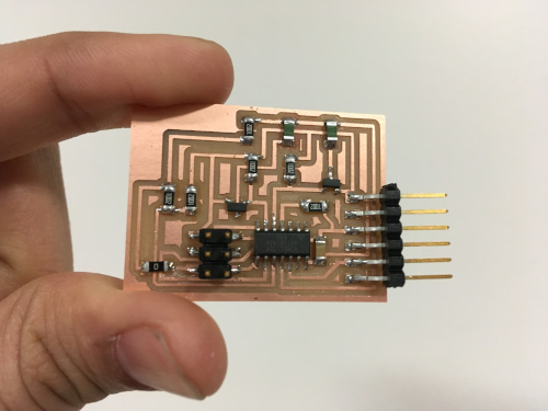
The first board I made ran into rc=-1 error while compiling. I figured out that there is a problem with the soldering and made a new board. This one turned out to be good.
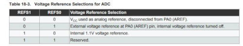
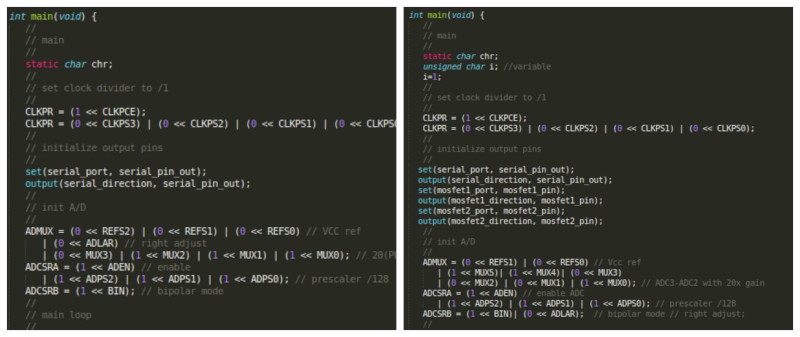
The most important step here is identifying appropriate registers and assigning bits after referring to Attiny44 datasheet. Each register has 8 bits. We need to set the reference voltage by using ADMUX register in attiny 44. First two bits of ADMUX are used for setting voltage reference!
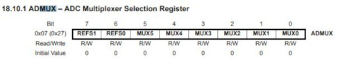
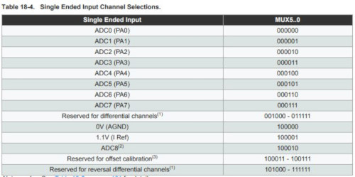
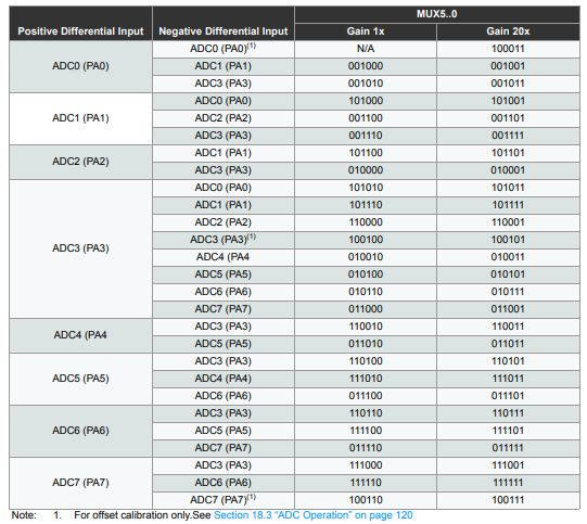
As shown below the other 6 bits can be used to perform single ended input channel selection and differential input. In my case I need differential input since I need to measure the voltage difference between ADC3 and ADC2 with 20x gain [we account for this gain during convertion the python code!] which is 110001 .
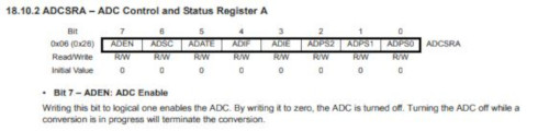
To enable ADC, one should assign 1 to ADEN ADCSRA register and I used the prescaler as it is like in Neil's code by setting it to 128
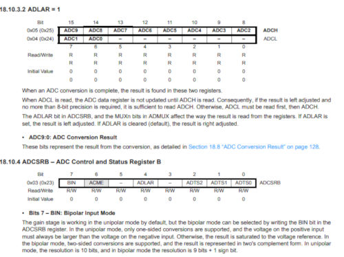
Something I observed: ADLAR is present in ADMUX register for attiny45 and it is in ADCSRB for attiny 44. It's set to zero for right adjust. BIN is set to 1 for bipolar mode.
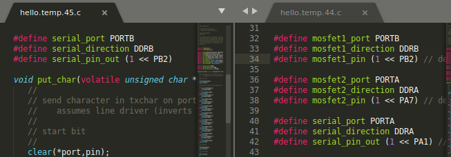
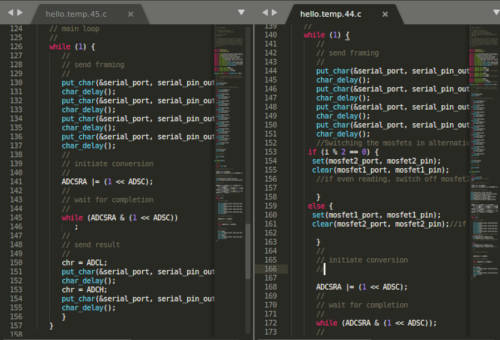
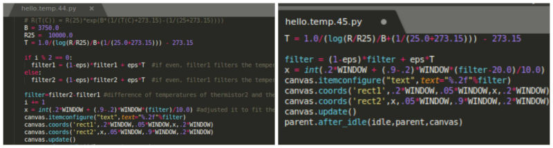
These are the changes I made to Neil's code which was originally meant for attiny45 so that I could compile attiny44 for differential temperature measurement.
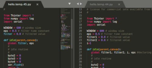
Changes in python code:
Programming:

Result: I could alternate switching between mosfet1 and mosfet2 and could measure the temperature difference between the thermistors.
I wanted to know if the board I first made without the pullup resistors work when I refined the code. It didn't work.
c code: hello.temp.44.c
makefile: hello.temp.44.make
python: hello.temp.44.py
Further changes in the program both in .c and .py file is discussed in Week11