Week 6: Embedded Programming
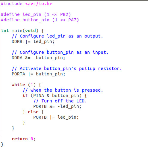
This week, I had to program the Hello world board I made in Week4. Thanks to Erik, Ravi for their valuable inputs explaining me the basics of embedded programming. I read AVR Tutorials on how to configure pins as inputs/outputs and activating them. Here is the code I used to program my board with my USP tiny I made in Week2. It is supposed to turn off the LED when the button is pressed.
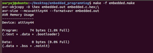
Here are the programming steps:
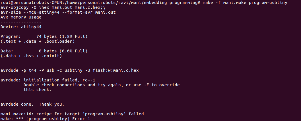
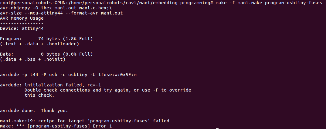
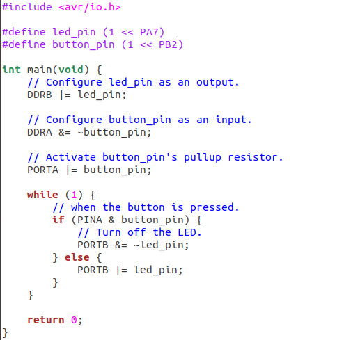
There was an error asking to double check the connections with rc=-1 error. I know for sure that the problem is not with the soldering or board as I could program the board with Hello world code in week4. I figured out that it's because I used a non-ADC pin(PA7) for the input device (switch). So it wasn't able to take the analog signal. I made a new board, this time I used PA7 for input device (switch) and PB2 for LED.
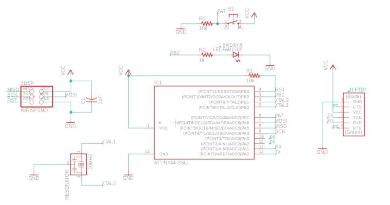
Board:
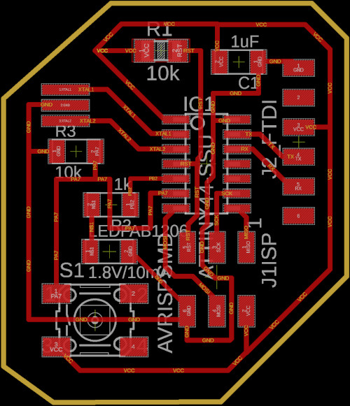
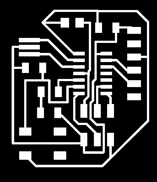
Traces and Outline:

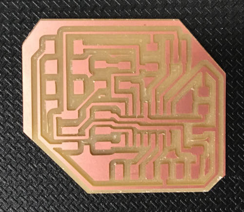
Board after milling using Rolad Modela MDX-20:
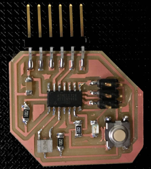
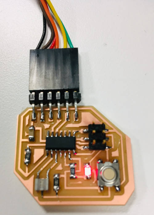
Board after soldering components:
Changes in the program:
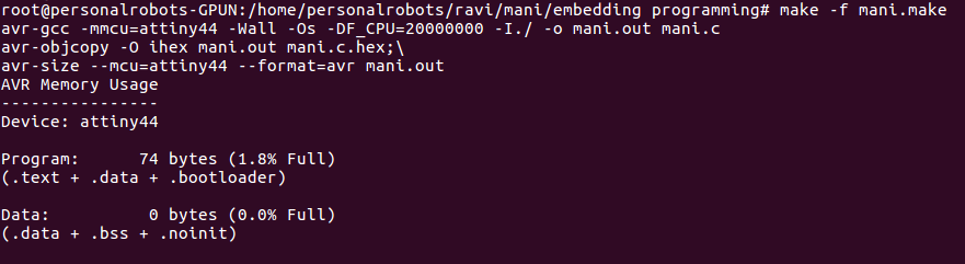
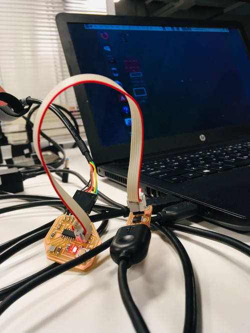
Programming new board with USP tiny:
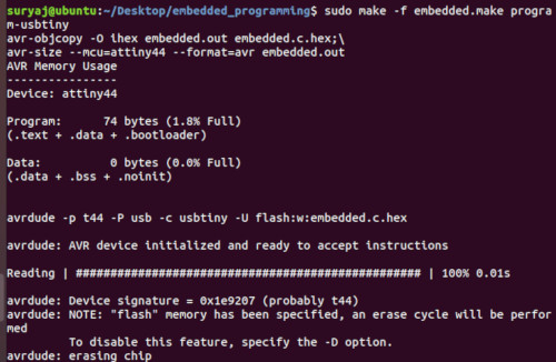
It works well this time.
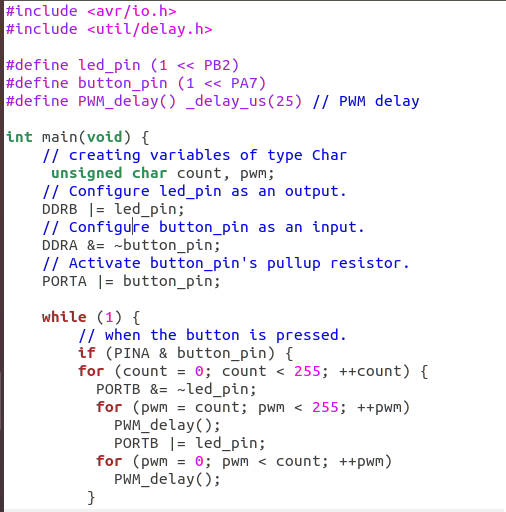
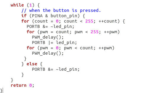
I wanted the LED to blink with increasing intensity. At first I modified the code taking Neil's input devices' code as reference. I got an error message saying that PWM_delay function didn't exist. Then I realized I didn't include the util/delay.h library. Here is the code that makes LED blink with increasing intensity.