
Week 5: Computer-Controlled Machining
Assignment: Make something big with wood
I want to make a flexure with wood. I have seen many wooden flexures online, but I have never seen one made out food with my own eyes. I want to make a flexure to confirm that wood can bend. Out of all, I wanted to make a clothbin to keep clothes. It should consist one bottom plate which can host the circular flexure and a top plate to cover the bin. For this assignment, we had to work in pairs, I worked with Elena.
Machines: Shopbot
Softwares: Solidworks, Vectorpro, Shopbot3.
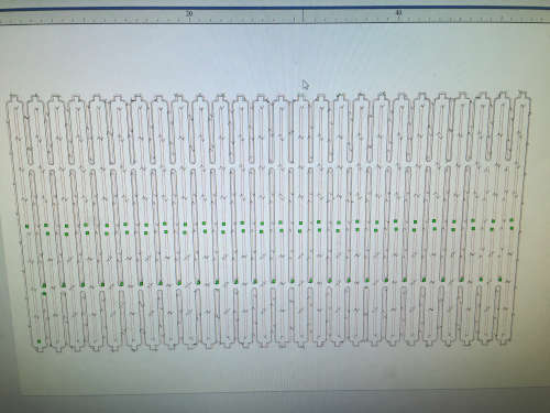
I designed the CAD file in solidworks. My initial design rules are: I need a 40cm inner diameter cloth bin. Thickness of the wood is 0.5 inch=1.27cm. Therfore, Outer diameter 41.27cm Length of the flexure=Circumference=Pi*d= 129.5878=130cm (130.81) Total Height of the bin = 70cm (67.46) The wood needs to be 130cm length and 70cm width for the flexure. For the top and bottom plates, 1.27 cms thick base plate and 1.27 inches thick top plate. The dogbone slots are made such that Flexure rightly fits in the slot as shown in the figure below. I saved the file as .dxf. This can be imported to Vectorpro.
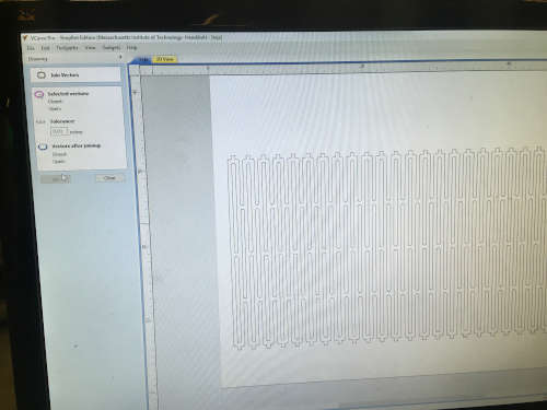
Once the file is imported, I moved my design close to the origin. By default, it imports the file in inches format. I designed my Solidworks file in CGS (Centimeter, Gram, Second) units. So I had to rescale it in inches. As Tom suggested us in the recitation, I put the material depth a little bit more than the actual so that the machine cuts through the wood. The thickness of the wood we used is 0.5inches and the material depth is set to 0.51inches. The software generated toolpath and I saved the file and the original file of Vectorpro. It’s good to have both. Once the design is ready to print, we set up the machine.
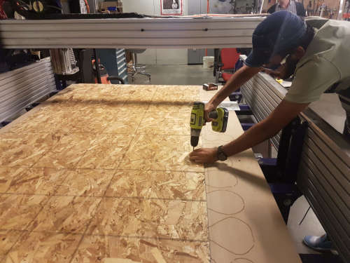
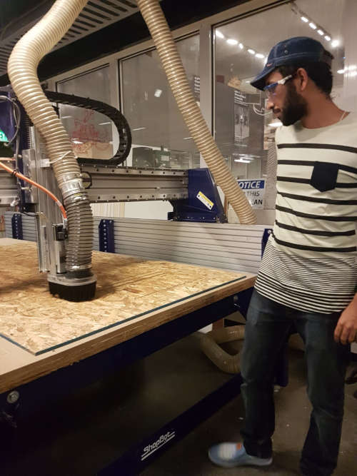
The machine has easy rules to follow. We need to use a sacrificial layer beneath the wood to be cut. The sacrificial layer is already set up and screwed to the machine bed. We place the wood on the top sacrificial layer and make through holes using appropriate drill bit and hand-drill along the edges. These holes are supposed to be only on the wood. One should not drill holes in the sacrificial layer. Then, we screw the wood into the sacrificial layer to make it immovable and good for cutting. If you screw correctly, it should be flat. After the machine is turned on, one needs to put the appropriate end mill in the end mill holder by using wrenches, make sure it’s tightly held in place. After pressing the reset button, one can import the tool path to shopbot3 software. You can start the spindle and make sure the rpm is rightly set for the end mill you are using. Set the origin on the bed [Yellow window] away from the edges and the screws. Fix the X and Y axes and zero them, go to cuts-Zero Z. Place the aluminum plate associated with z-axis on the platform below the end mill and grant access to the machine to find the plate. Once machine touches the z-plate, your z-axis is zeroed. Now your origin is set.
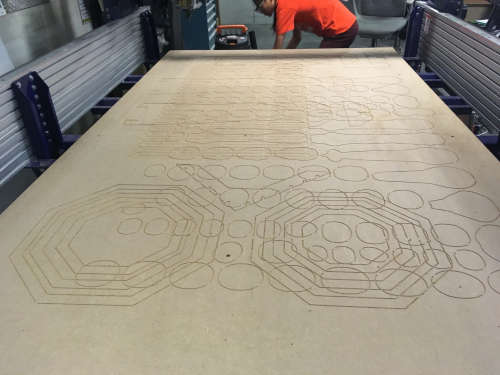
We set followed the rules as discussed above and placed the wooden sheet on the sacrificial layer and screwed it in at appropriate locations.
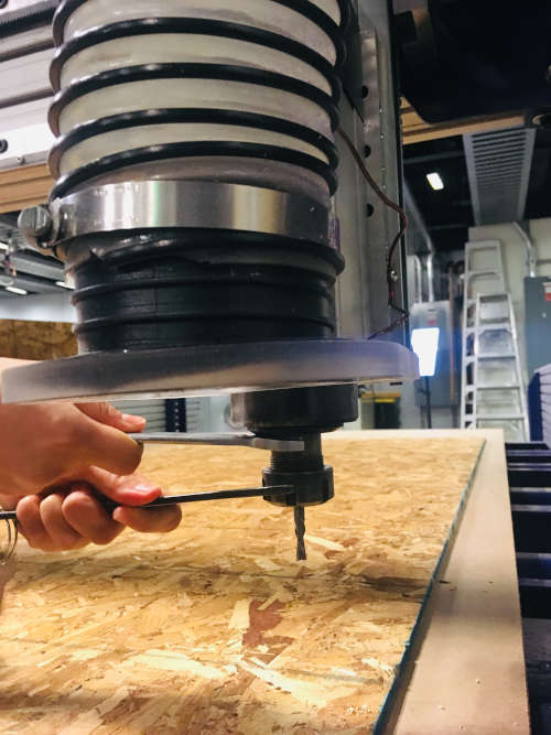
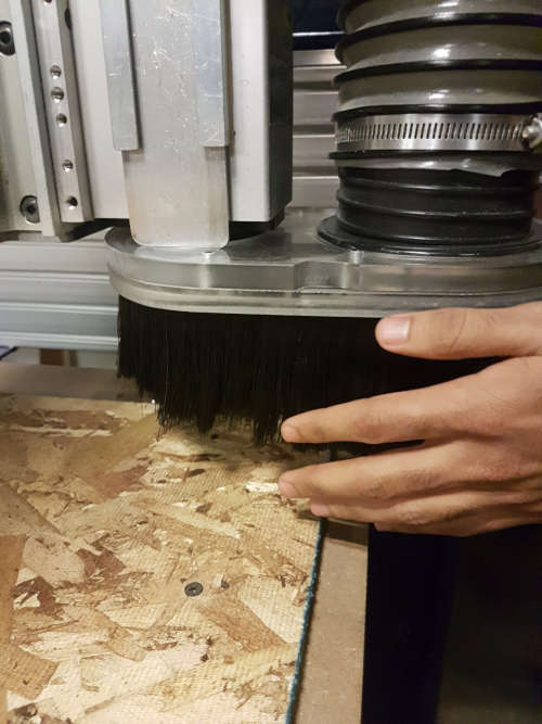
Then we fit the appropriate end mill using the wrenches. We made sure we places the holder with brushes which prevent cut wooden particles from flying.
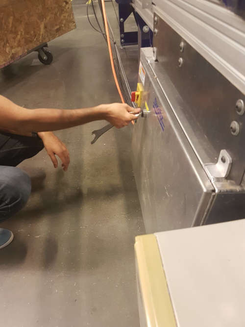
After zeroing the origin and we switch on the spindle and press the reset button.
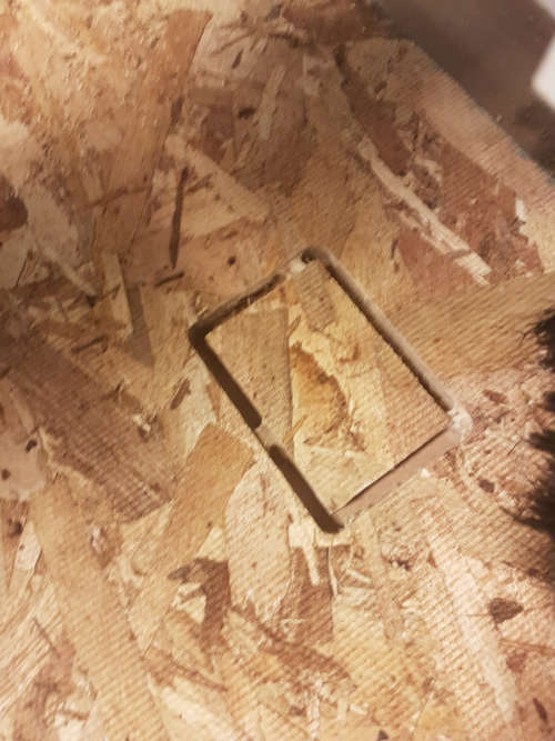
We made a test cut with a pad attached. Thanks to Sara Falcone who suggested us using pads when cutting flexures or any design in general. Pads prevent the part that’s being cut from moving. They keep the part in place. One can remove these pads after the cutting time by using a razor cutter. From here on, I added pads to my tool path.
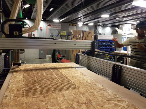
I started cutting my flexure finally after a test cut. The shopbot started cutting at different places. It wasn’t continuous. I was totally confused unsure of what’s happening. Then we figured out that it’s because we didn’t join the vectors when we imported the .dxf file.
After I joined the vectors, created a new tool path, the cutting process was smooth until it showed up an error. Fortunately, during the machine training session Tom told that this happens with shopbot and we need to restart the software and start cutting again. My file was half cut and I didn’t want to repeat the whole process again. Then I figured out that I can remove some parts of toolpath so that it cuts only those regions which were uncut. Apparently, one can change the gcode in shopbot3 instead of changing toolpath in vectorpro. Since I was unsure how to do it in gcode, I went ahead with deleting parts of toolpath in vectorpro. Since the shopbot wasn’t turned off, the origin remained same. Nevertheless, I made sure the origin was same the one before.
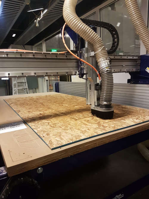
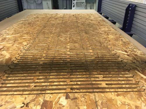
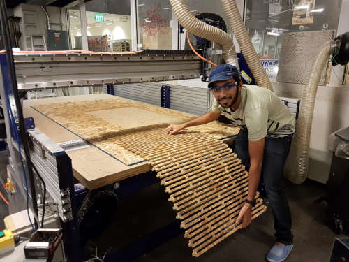
Shopbot cutting the flexure. During the cutting process, I observed that pads kept the flexure from moving. If I wouldn’t have used pads, the flexure wouldn’t have been properly cut.
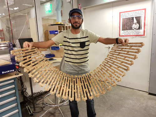
 I could bend wood!!
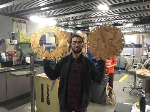
These are top and bottom plates I cut.
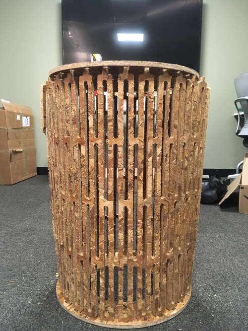
End result
Cad files and shopbot path files