Electronics Design
PCB Design
Files: Board traces, Board outline.
This week we had to design a PCB (redrew the reference design-echo hello-world board and add at least a button and LED on it), make it through milling, stuff it and program it. At the end we should have a board that can talk to a computer over a serial connection (masquerading as a USB device).
Board Design
I decided to use Kicad platform for designing my board, because it seemed very user-friendly when was presented during the class. After importing the fab library (preferences tab, manage footprint libraries option) and setting the design rules taking into concideration that I was going to use a 1/64" end mill to mill it (board setup option: clearance 0.4 mm; track width 0.4 mm; via size 0.8 mm; via drill 0.4 mm), I was ready to go.
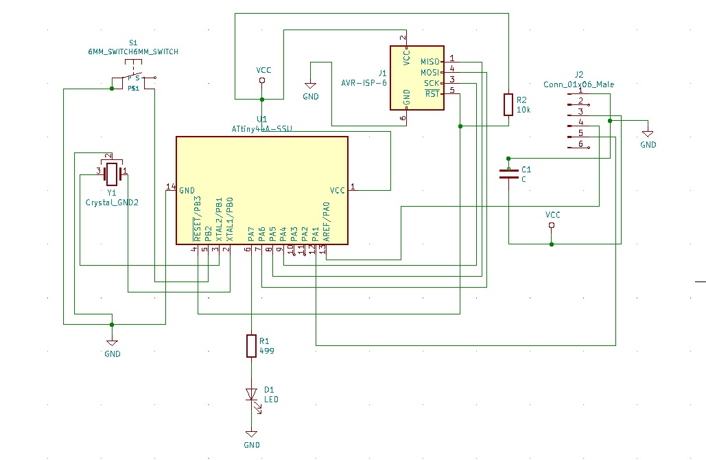
First I drew the schematic following the reference design and adding a switch and a LED with a current limiting resistor. In order to select the suitable current limiting resistor for the LED, I used an online LED Series Resistor Calculator. I entered the supply voltage (5V), the forward voltage (1.8V) and the forward current (10mA) and I found that a resistor of 320 ohms would be needed. I had to use a resistor rated higher than the one calculated, so I went with the closest value we stock in bulk: 499 ohms.
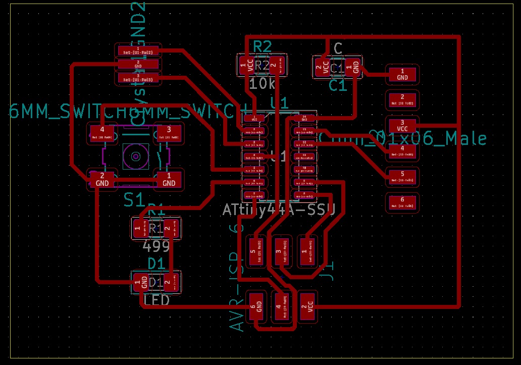
After drawing the schematic, it was time to draw the actual traces of the PCB board. Although it took me a few tries and about 3 hours to do it (I encountered unexpected issues, such as sudden program shutdowns, and I learnt to save every move I made the hard way!), I really enjoyed it. It was like trying to solve a riddle and I can say that I am pleased with the outcome. I look forward to designing more boards in the near future.
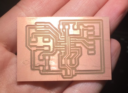
Production
I used the Roland SRM-20 milling machine, controlled with mods to mill my board. I opened the traces file first in mods and mounted the 1/64" end mill. After setting the origin and zeroing the tool Z-axis manually, I set the cut depth at 0.004", the maximum depth at 0.008" and the offset at 4. I then sent the file to the machine and everything went smoothly.
After milling the traces of the board, I mounted the 1/32" end mill to the machine and I imported the outline file in mods. I used the default settings, set the origin, zeroed the Z-axis and sent the file to the machine. My board was ready!
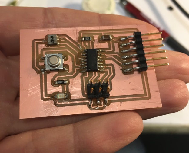
Then, I went and found the necessary components to be mounted on my board:
- 1x ATtiny44 SSU
- 1x 10kΩ resistor
- 1x 499Ω resistor
- 1x 20 MHz resonator
- 1x 1μF capacitor
- 1x 2x3 pin header
- 1x 1x6 pin male connector (FTDI)
- 1x 6mm Switch 0.05A 24V
- 1x red LED (1206 SMD)
Although I had tried soldering during the 3rd week of HTMAA and I liked it, I felt very uncomfortable with soldering my board this time. Thank god Zach sat with me once again and showed me how it is done (thank you so so much Zach!). So, I managed to do it, but I don't feel very pleased with my joints this time.
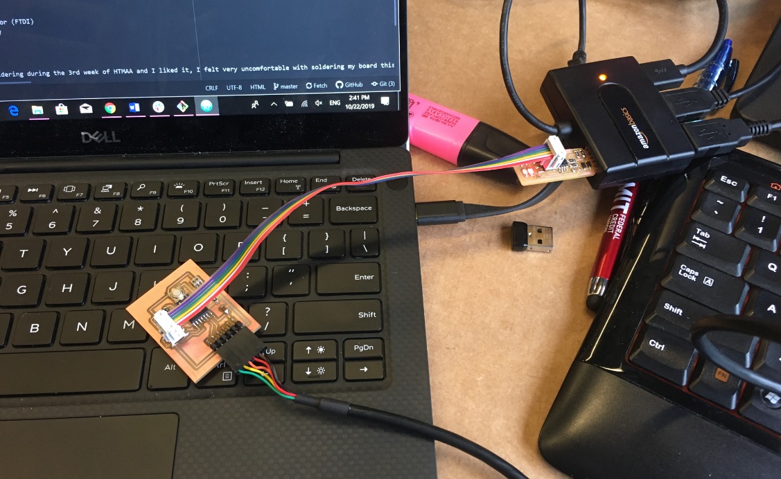
Programming
I used the USBtiny board, which I made during the Electronics Production week to program my board. I used an FTDI cable (5V) to connect my board with my computer (black wire on the FTDI cable was connected to GND) and an ISP cable to connect the board with the USBtiny programmer (the USBtiny was also connected with my computer), as shown below. The orientation of the ISP cable was selected in such a way that the cable connected to GND pin in the board (purple cable) to be connected also to GND in the other board.
Then, I downloaded Neil's c code and make file to program the board and saved them in a specific directory inside the C folder. I opened Git Bash and went inside the directory where the c code and the make file where located. Then, I ran the following commands:
- make -f hello.ftdi.44.echo.c.make (in order to produce the hex file);
- make -f hello.ftdi.44.echo.c.make program-usbtiny-fuses (make fuses command);
- make -f hello.ftdi.44.echo.c.make program-usbtiny (flashing of the developed microcontroller).
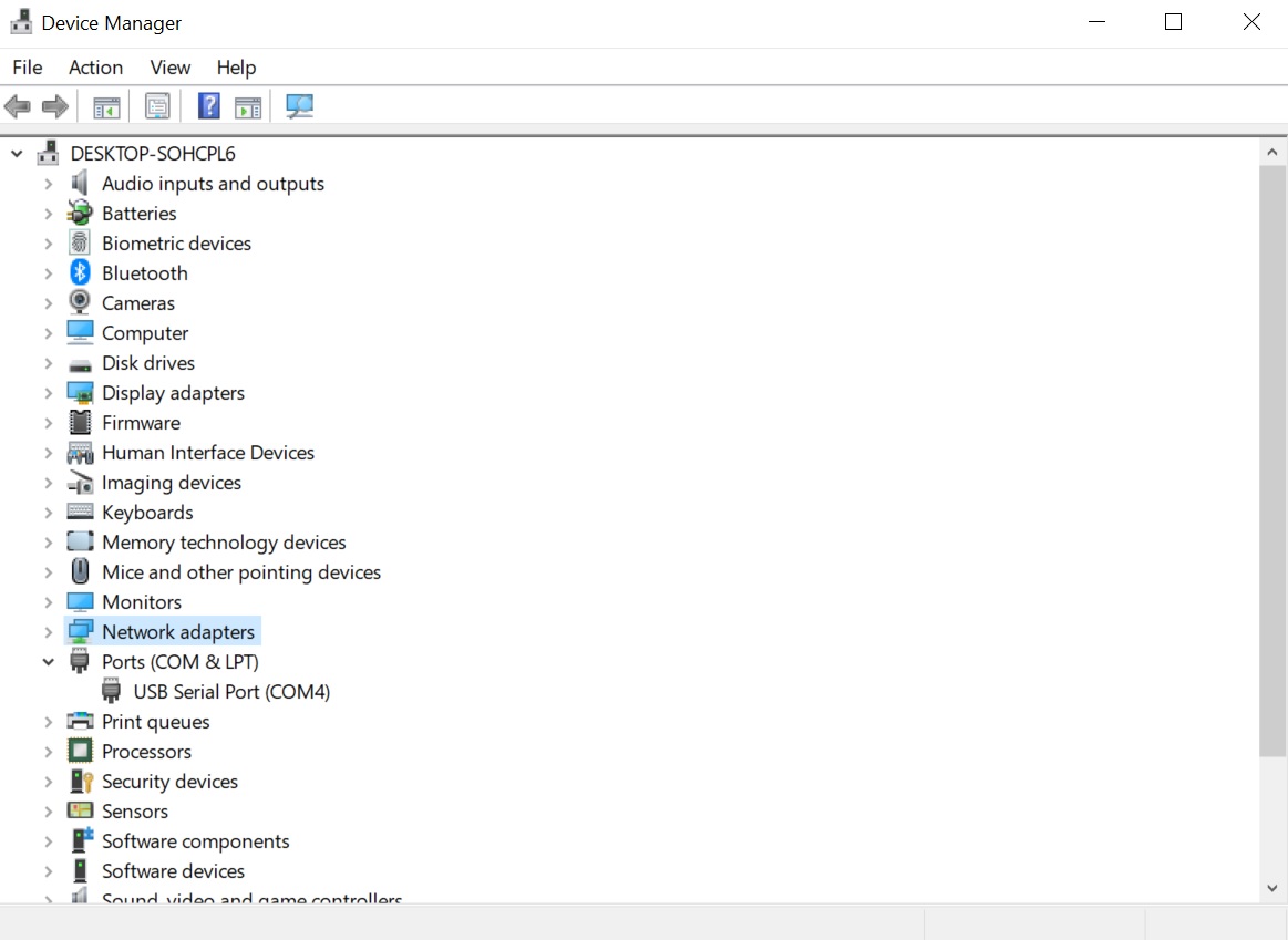
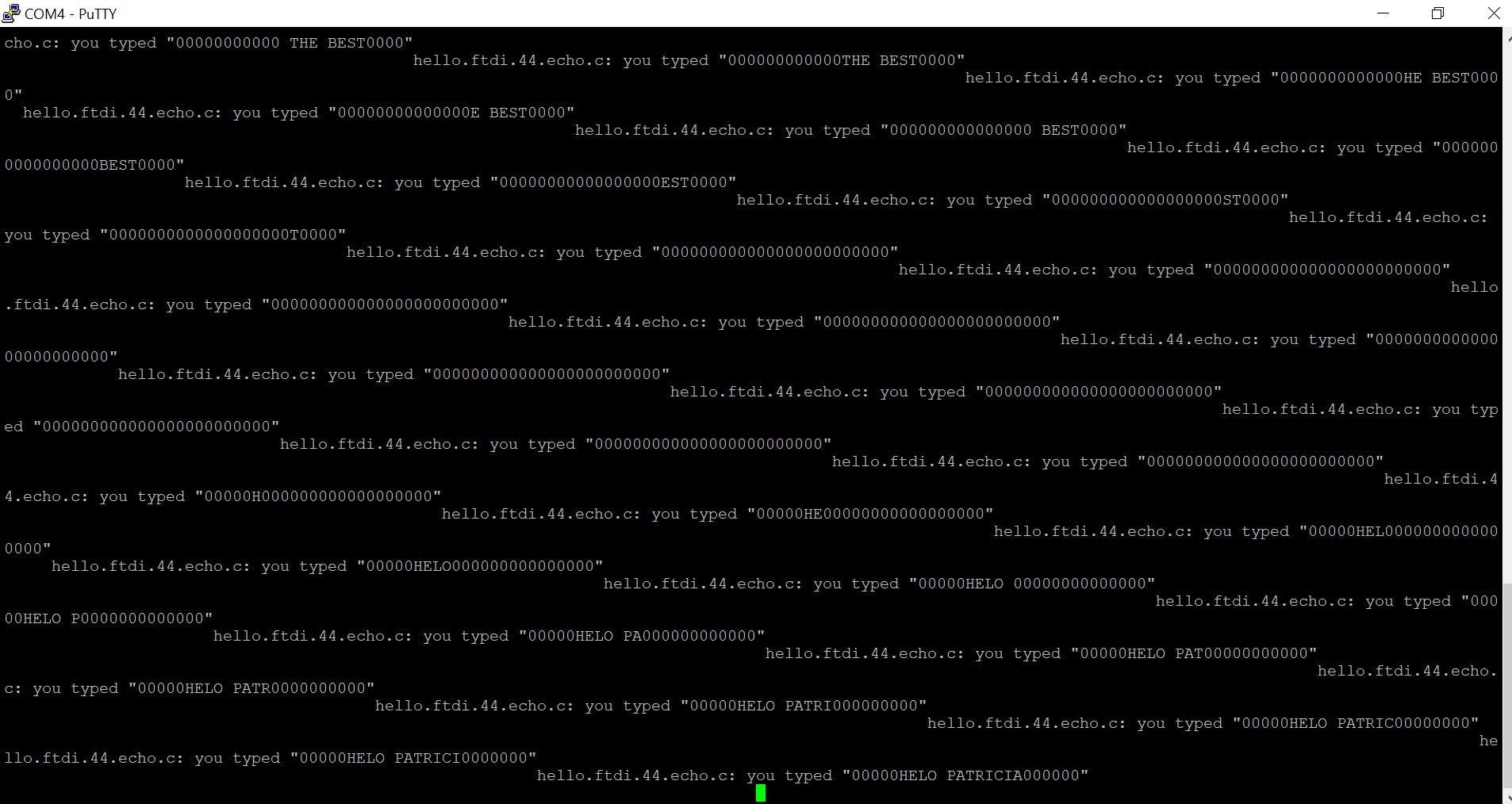
Then I tested my new board. I removed the USBtiny programmer and left only the new board connected to my computer through the FTDI cable. Then I downloaded PuTTY in order to have a serial terminal to talk to my board. I checked which COM port was in use through the Device Manager of my computer and it was COM4. So, I opened PuTTY and selected connection type: serial, serial line: COM4, and speed: 115200 in the PuTTY configuration and then hit open.