Output Devices
Files: Board traces; Board outline; hello.servo.44.2.c; hello.servo.44.2.c.make.
This week we’re exploring output devices, i.e. pieces of hardware that are used to display or output data which has been processed by or stored in our microcontrollers, such as actuators and screen displays.
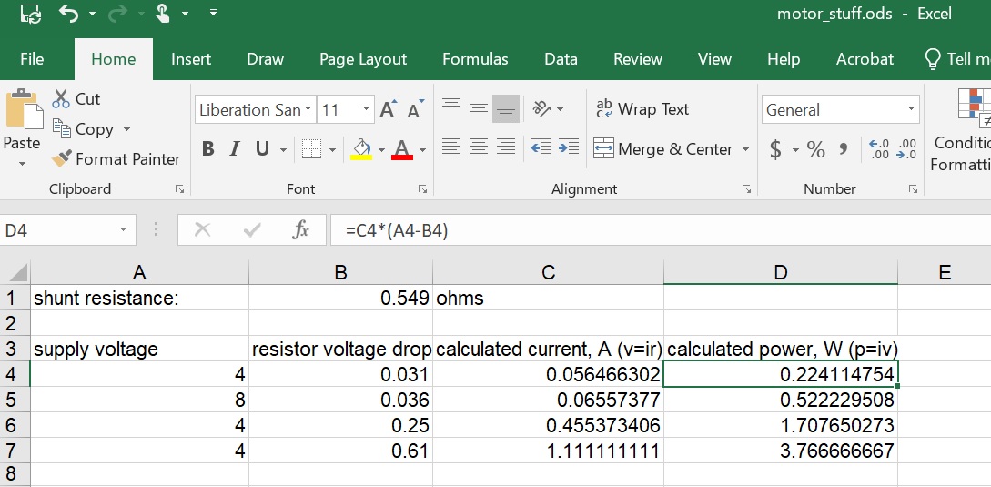
During the group assignment (team: Zach, Aubrey, Afonso, Sabrina, and me) we measured the power consumption of a gear motor. We connected the gear motor to a resistor of known R (0.549 Ω) as well as to a DC power supply and a multimeter.
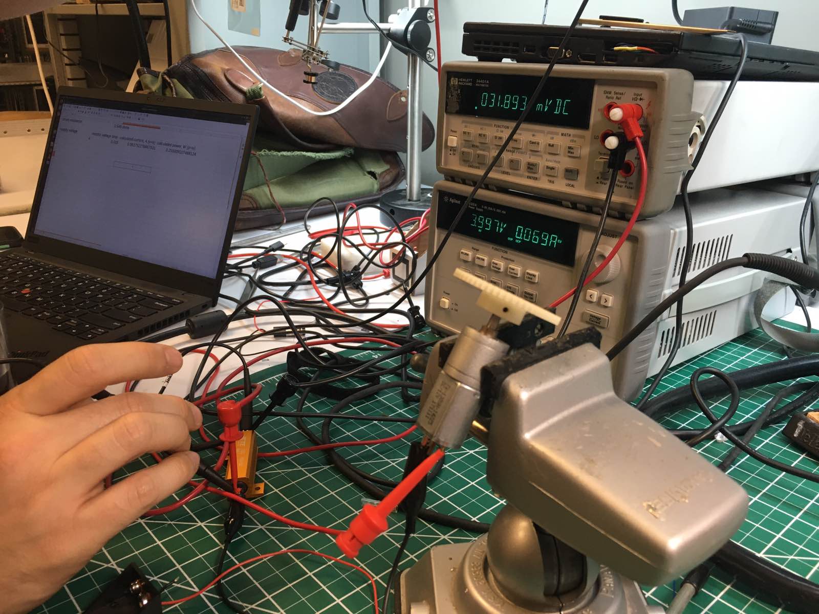
We supplied voltage to the resistor and measured the voltage drop across it (ΔV). Follwing Ohm's law (I=ΔV/R) we calculated the current going to the motor (I). The voltage going to the motor was the initially supplied voltage minus the voltage drop due to the resistor. So, we calculated the voltage going to the motor and multiplied it with the current to calculate the power consumed by the moter (P=I*V). We also saw that by trying to hold the gear of the motor and don't allow it to spin, it's power consumption was significantly increased, as it was trying harder!
For my final project I need actuators for the locomotion of my fish. Servo motors can be used for moving the tail and the fins of the fish, so I decided to make a board and connect it with a servo motor this week.
PCB Design
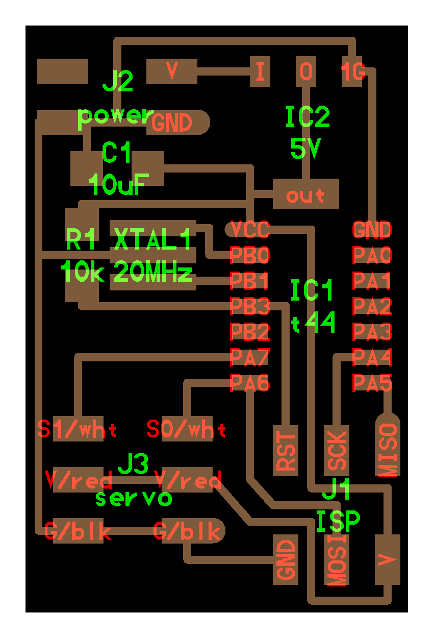
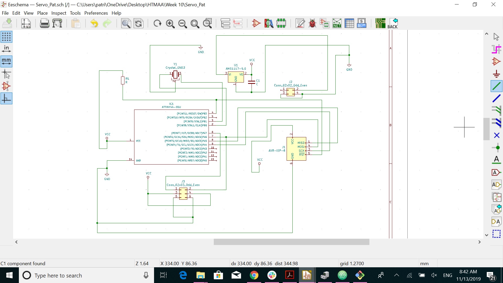
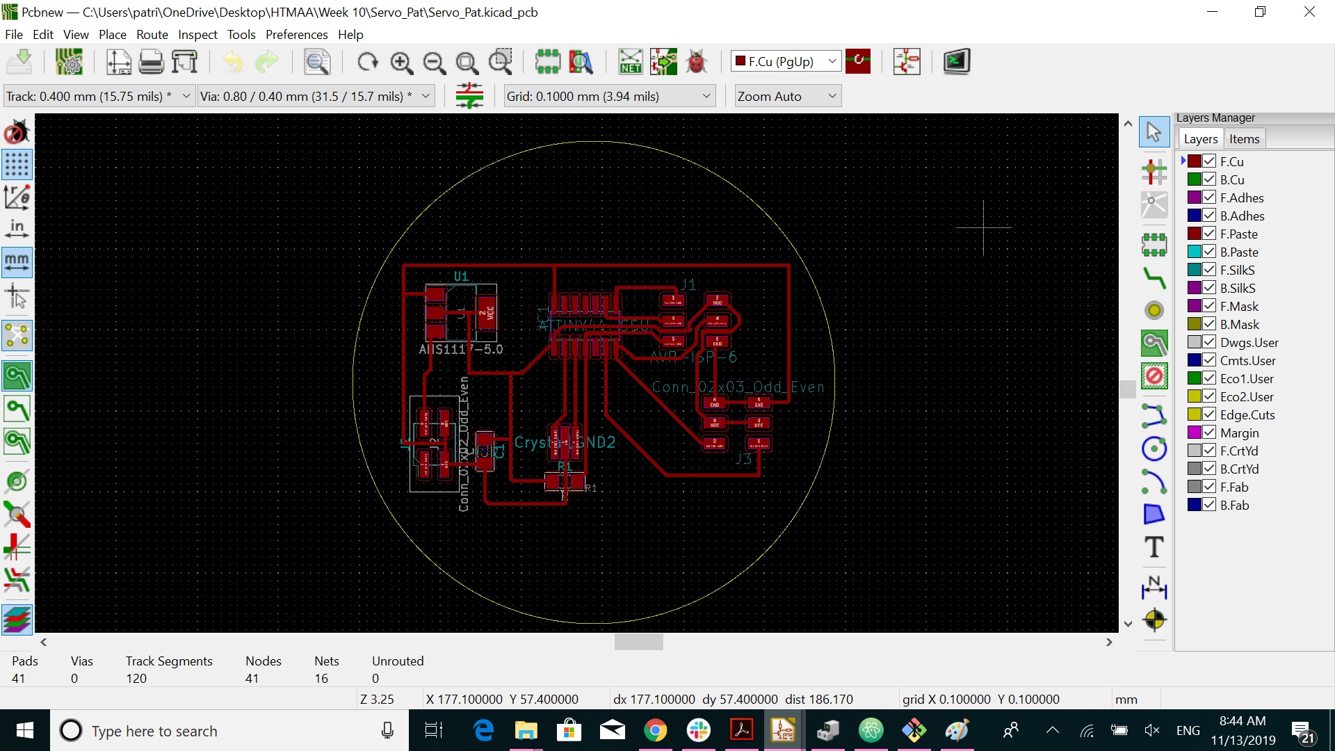
I redrew Neil's servo motor board using the Kicad platform (board setup option: clearance 0.4 mm; track width 0.4 mm; via size 0.8 mm; via drill 0.4 mm).
First I drew the schematic, following Neil's design and then I drew the traces and the outline of the board.
Production
I used the Roland SRM-20 milling machine, controlled with mods to mill my board. I opened the traces file first in mods and mounted the 1/64" end mill. After setting the origin and zeroing the tool Z-axis manually, I set the cut depth at 0.004", the maximum depth at 0.008" and the offset at 4. I then sent the file to the machine and everything went smoothly. After milling the traces of the board, I mounted the 1/32" end mill to the machine and I imported the outline file in mods. I used the default settings, set the origin, zeroed the Z-axis and sent the file to the machine. My board was ready!
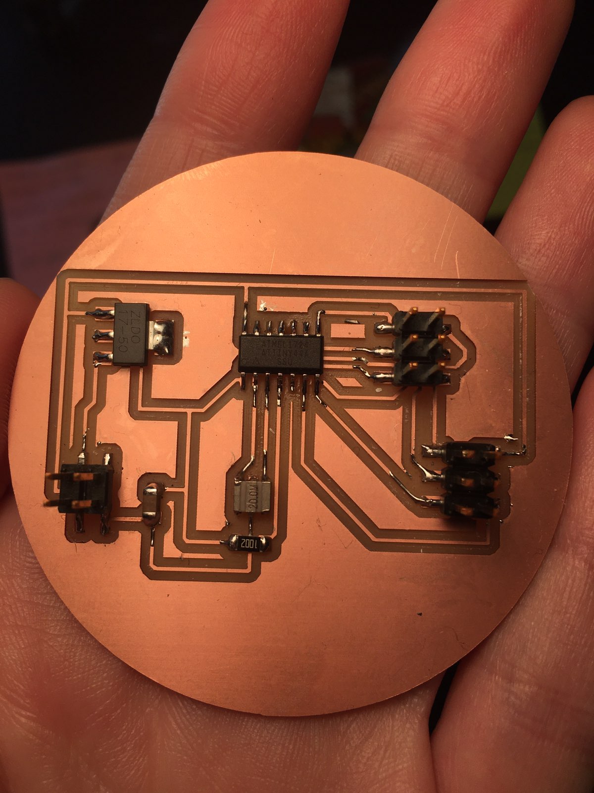
Then, I went and found the necessary components to be mounted on my board:
- 1x ATtiny44 SSU
- 1x 10kΩ resistor
- 1x 20 MHz resonator
- 1x 10μF capacitor
- 1x ZLDO117-5V regulator
- 2x 2x3 pin header connector
- 1x 2x2 pin header connector
Soldering went pretty smooth; I have started to like it actually!
Programming
I used the USBtiny board, which I made during the Electronics Production week to program my board. I followed the same procedure as in the Electronics Design week, using Neil's c code and make file to program the board and saved them in a specific directory inside the C folder. I opened Git Bash and went inside the directory where the c code and the make file where located. Then, I ran the following commands:
- make -f hello.servo.44.2.c.make (in order to produce the hex file);
- make -f hello.servo.44.2.c.make program-usbtiny-fuses (make fuses command);
- make -f hello.servo.44.2.c.make program-usbtiny(flashing of the microcontroller).
Actuation
As soon as the microcontroller was programmed it started to move!! Woohoo!! I first powered it through 4 AAA bateries (6+ cummulative voltage) and then I connected it to a DC power supply (5+ voltage, 0.1 A).