CNC Machining
Make Something Big
Files: Fish 3D design (designed with Fusion 360), Fish 2D design (designed with Fusion 360 Slicer).
Design
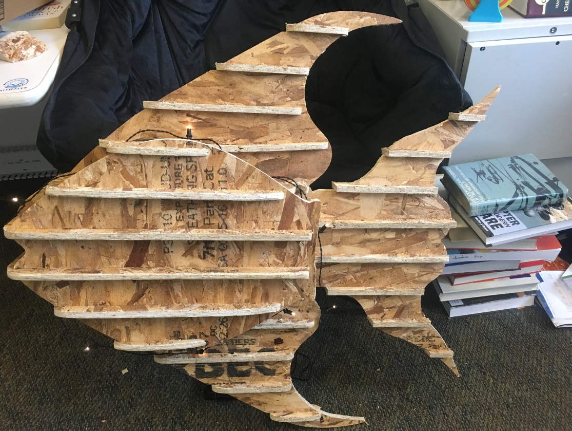
This week we have to make something big. Actually we have to design, mill and assembly something big, made out of Oriented Strand Board (OSB) material. The first idea that came to my mind was to design furniture. But then, I thought that I just moved in a furnished apartment and I struggled selling my old furniture online during summer. Also, I just made my desk for my new office at CBA out of cardboard. So, I wasn't really in the mood for making new furniture. Then, I was trying to connect this assignment with my final project, aka the robotic fish. Practically, I couldn't find any connection. And then I had an idea, inspired by my final project: making a big fish, which could serve as a lighting and/or decorative object/sculpture. So, I decided to make a big fish!
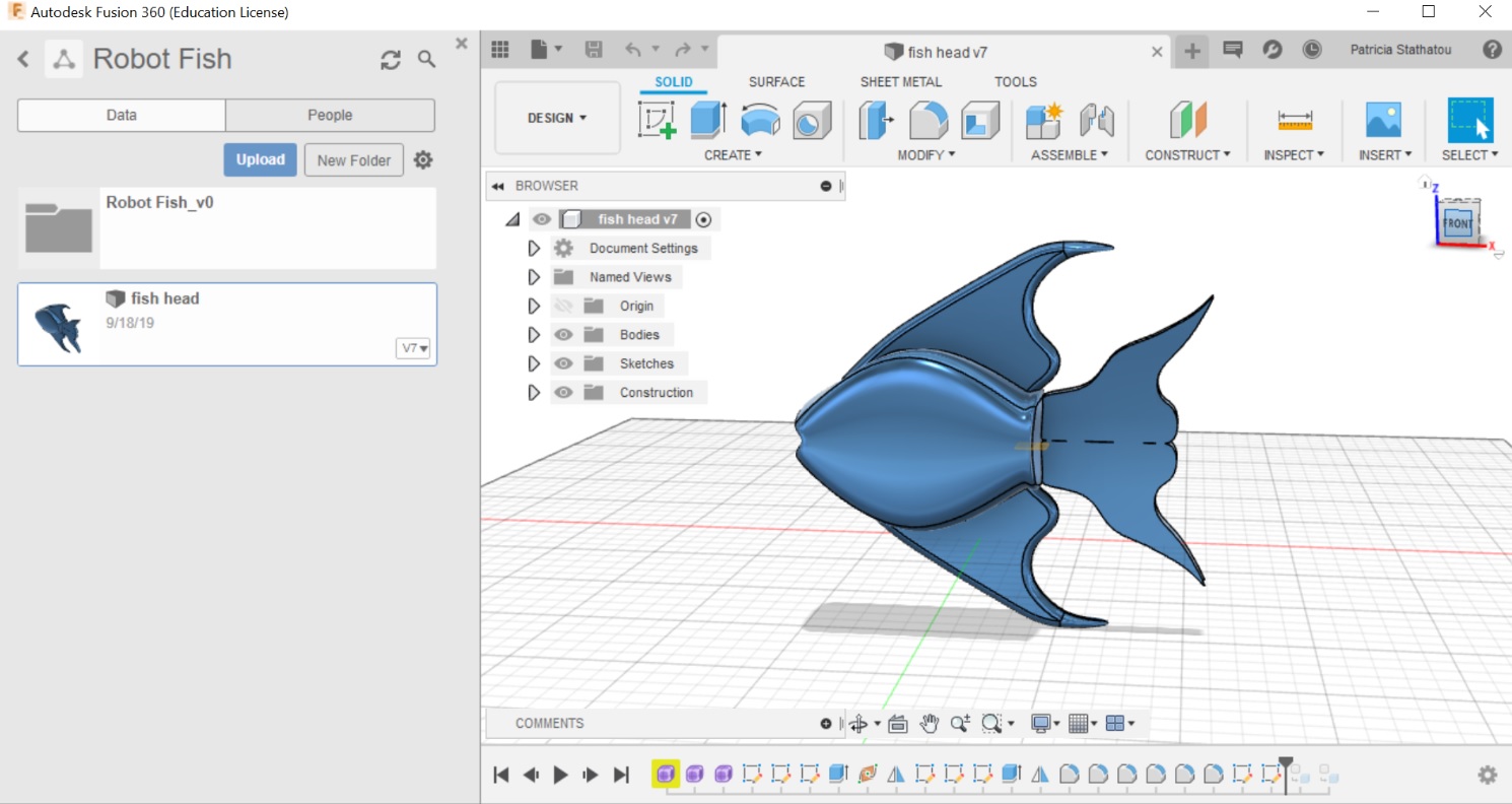
I used the 3D model developed in Fusion 360 during the 3D Printing and Scanning week.
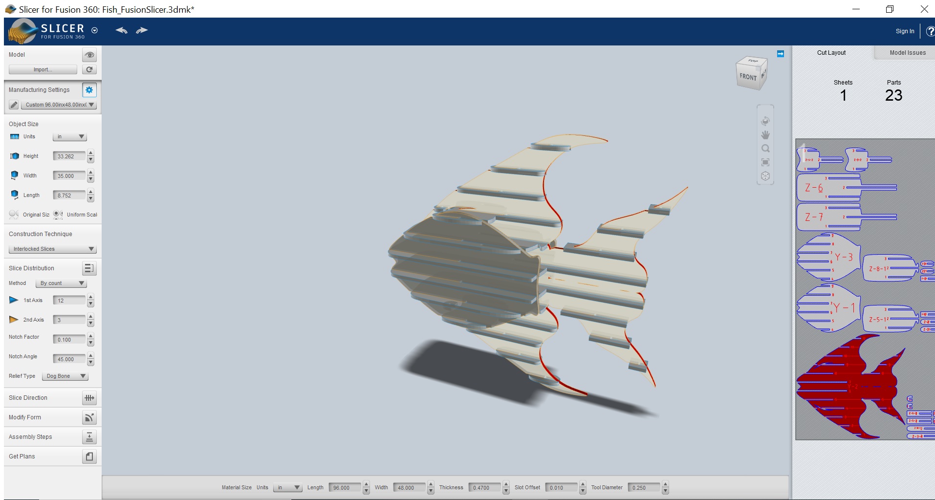
I imported the 3D model (dxf file) in the Slicer for Fusion 360 program to convert it into 2D parts. I developed a new material in the program's manufacturing settings library defining the dimensions of the OSB sheet (96" x 48"), its thickness (0.47") and the diameter of the tool that I was going to use for milling (0.25"). I chose the construction technique "interlocked slices" to develop the 2D parts. The model parameters, the 2D parts and their cut layout are shown in the image below:
Machining
After being trained in the Shopbot PRSalpha 120-60 CNC milling machine, I did the group assignment with Jiri to test the runout, alignment, speed & feed, and toolpaths of the machine. I first developed a square (side 80 mm) in Fusion 360 and imported it in the machine software (VCarve Pro ShopBot Edition) to see how the units of the file are being interpreted by the software. The software was reading the 80 mm of each side either as 80 inches or as 8 mm, so I learnt that I had to design my file in inches to avoid unit complications. We designed new squares (side: 80 mm) on the software environment with Jiri and cut 3 of them and measured their dimensions. We measured that in Y direction the sides of the squares were slighlty longer compared to X direction (about 0.13 mm), and we observed that the longer sides were about 0.95 mm shorter than the design sides. The angles were pretty squared though.
We then created smaller internal squares inside the initial squares and played with the toolpath selection of inside and outside vectors to understand how different selections affect the final resulst. As we already expected, we learnt that internal featured should be cut using the inside vector selection.
We didn't test different speed and feed settings, as we were adviced not to do so, but as we learnt during the training the optimal settings for our material are feed: 10,000 rpm, spindle speed: 120 inch/min, plunge rate: 60 inch/min.
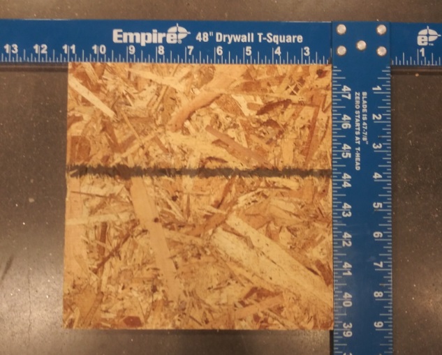
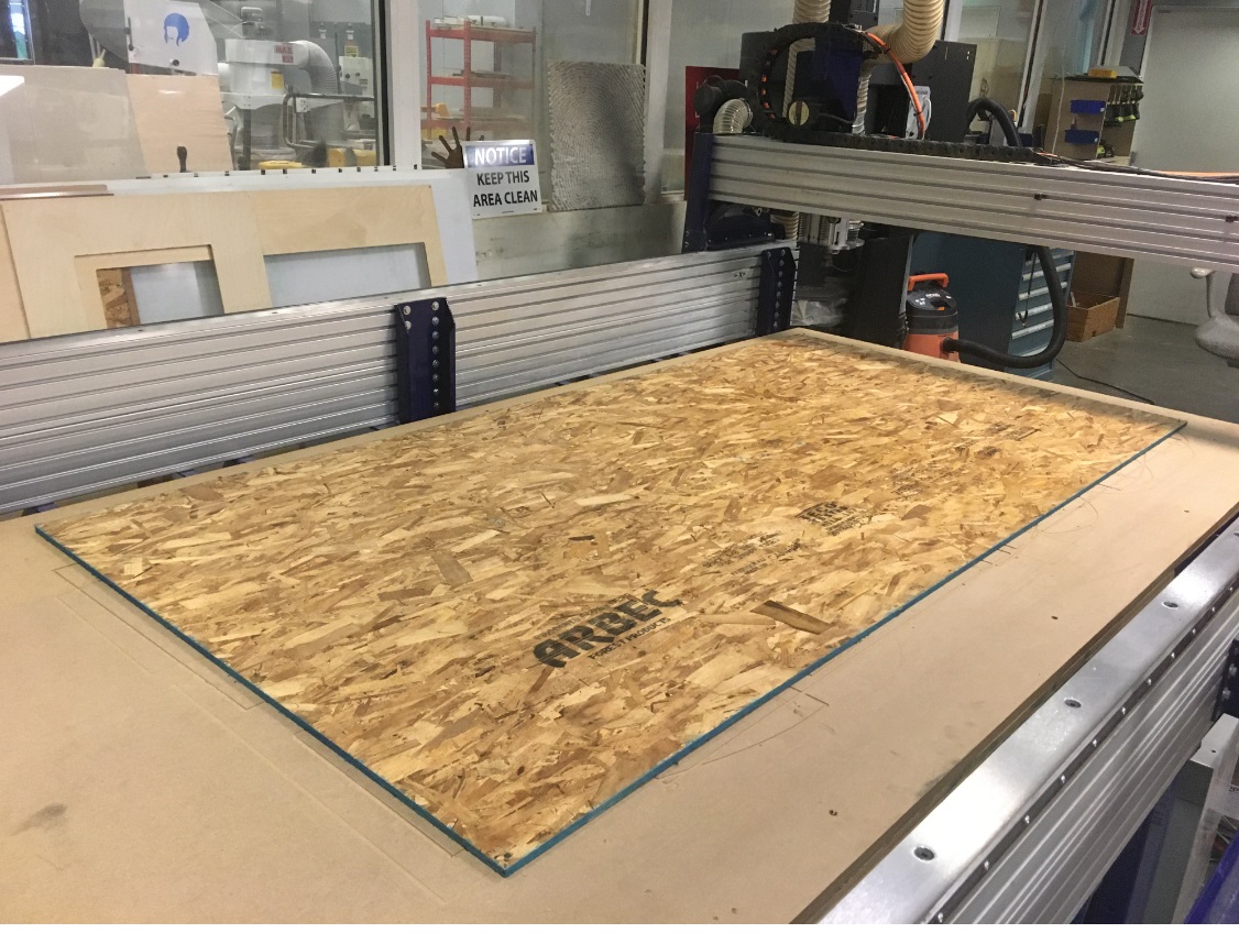
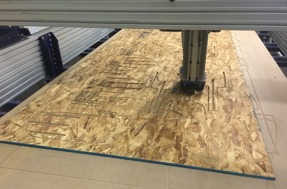
After the training and the group assignment I felt ready to cut my parts (little did I know!). I went to the shop very optimistic, and I first mounted my board on the ShopBot bed.
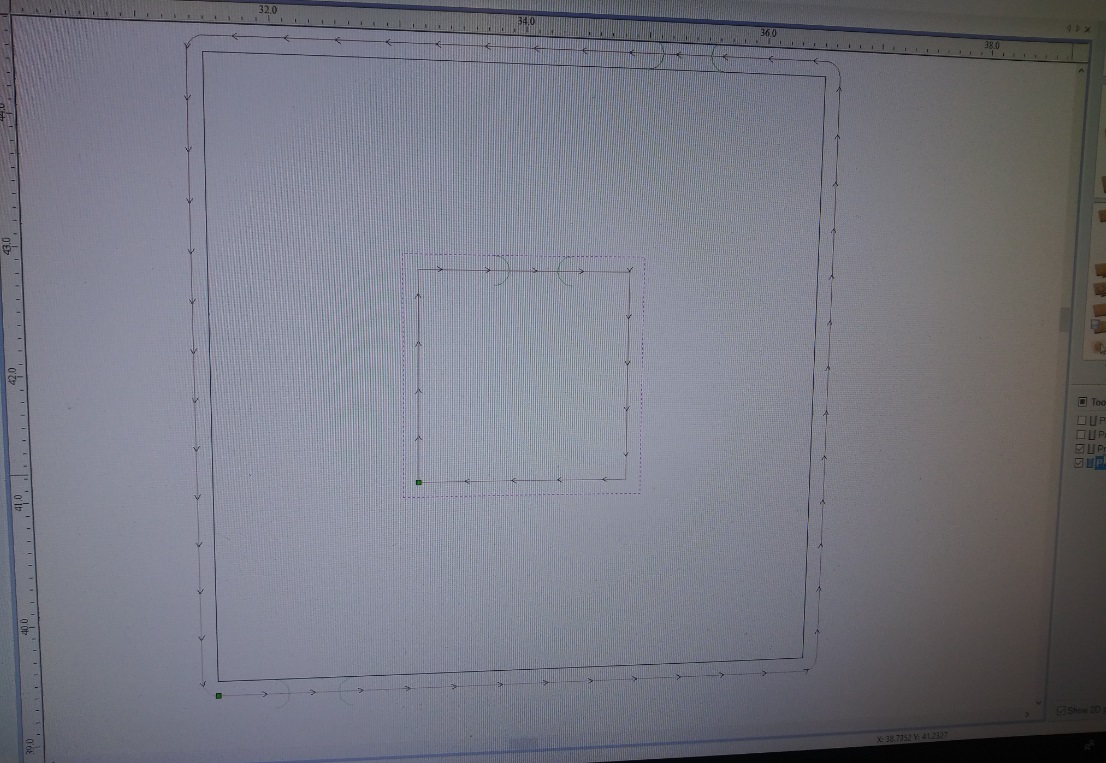
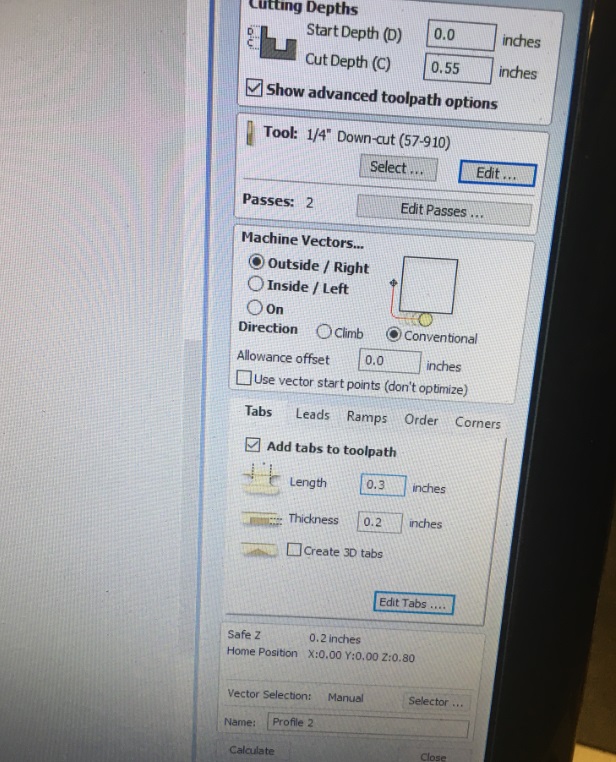
Then, I inserted my file in the software, edited the cutting conditions, added the quarter inch endmill to the ShopBot and started. After about 2-3 minutes of cutting I realized that I had selected the wrong endmill! Although it was a quarter inch endmill, it was upcut instead of downcut and the parts were coming out very unsmooth. So, I stoped, changed the tool and started again. After 10 mins I started observing that some of my parts were not being cut out completely, and that the machine was leaving parts of the shapes uncompleted. I paused and checked the toolpaths again but I could not figure out why this was happening. When I viewed the toolpaths in the 3D viewer mode I realized that there were open shapes that were not supposed to be cut by the machine. This was strange because I had already edited and joined all the segmented vectors of my file. And then, James, who was around and heard me nagging (thank God!), gave me the answer. I had leaved the tab dimensions in the default values of the software, i.e. 5"x3", although I had parts way smaller than that! That's why the machine was refusing to cut these parts completely!
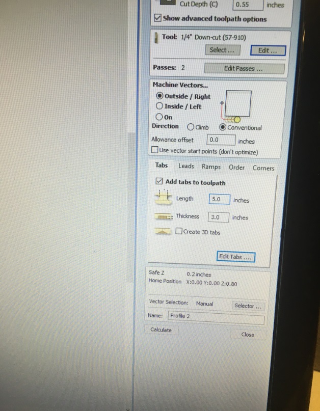
I changed the tab settings and edited their dimensions, selecting tabs of 0.3"x0.2".
Then, I put a new board on the bed and started again. After 15 mins I realized that (guess what!) I chose the wrong XY orientation for my design and the tool was about to cut outside of the board. Thank God I saw this ontime and paused the operation. I managed to restard and cut the remaing parts on the same board by removing the toolpaths of the parts that were already cut form the software and moving the rest toolpaths in the remaing part of the board. Finally, my parts came out successfully cut!
Assembly
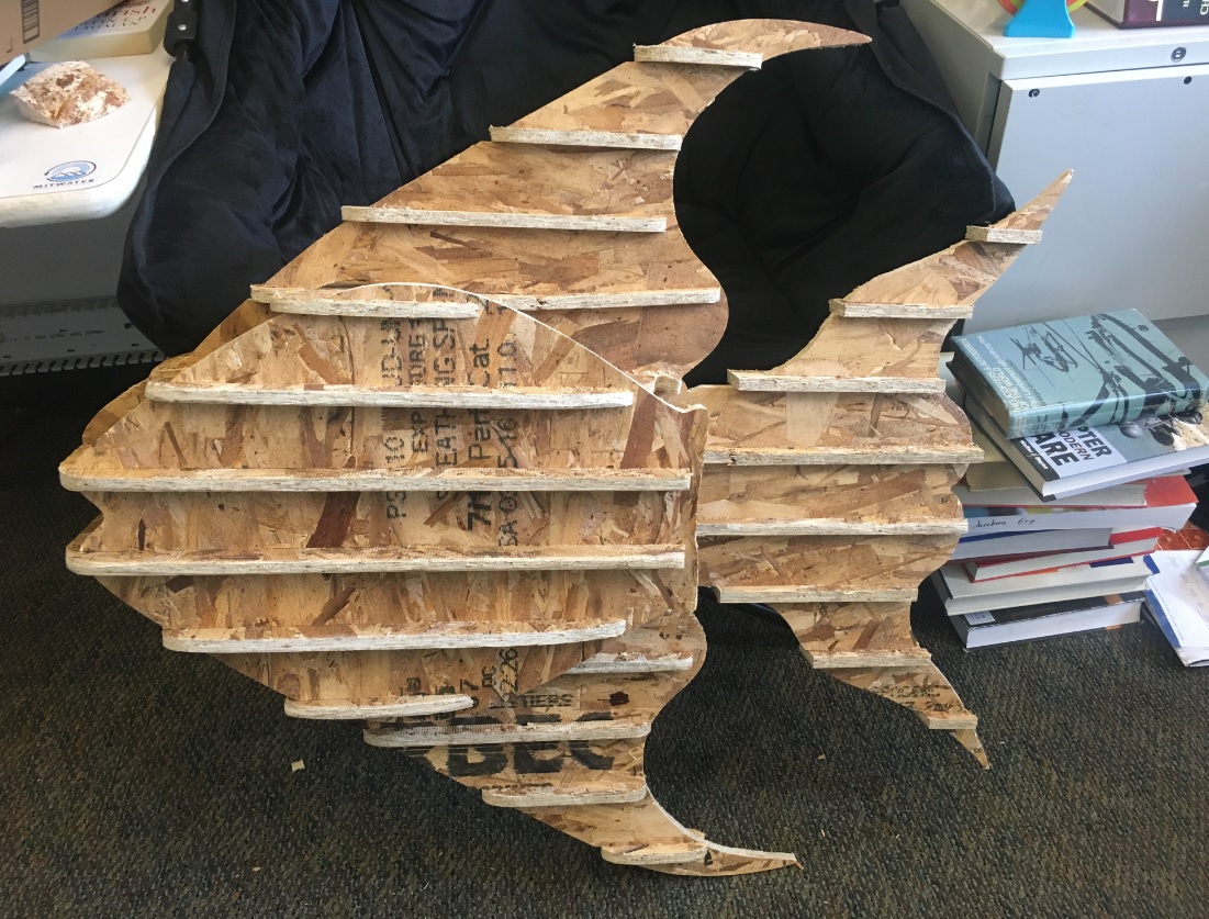
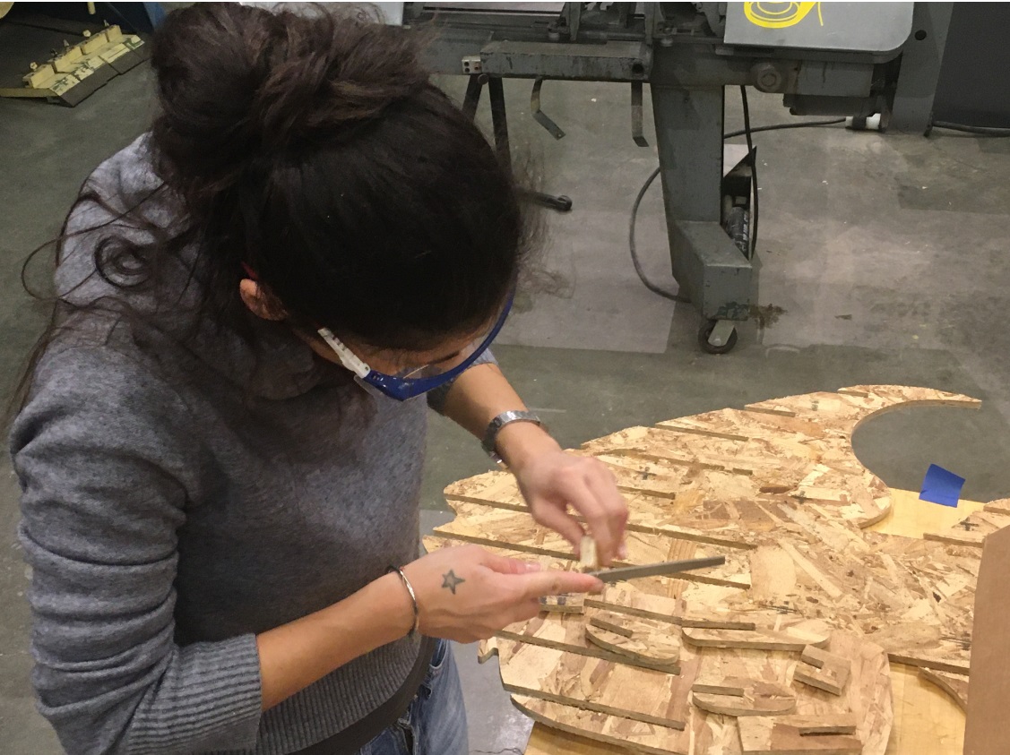
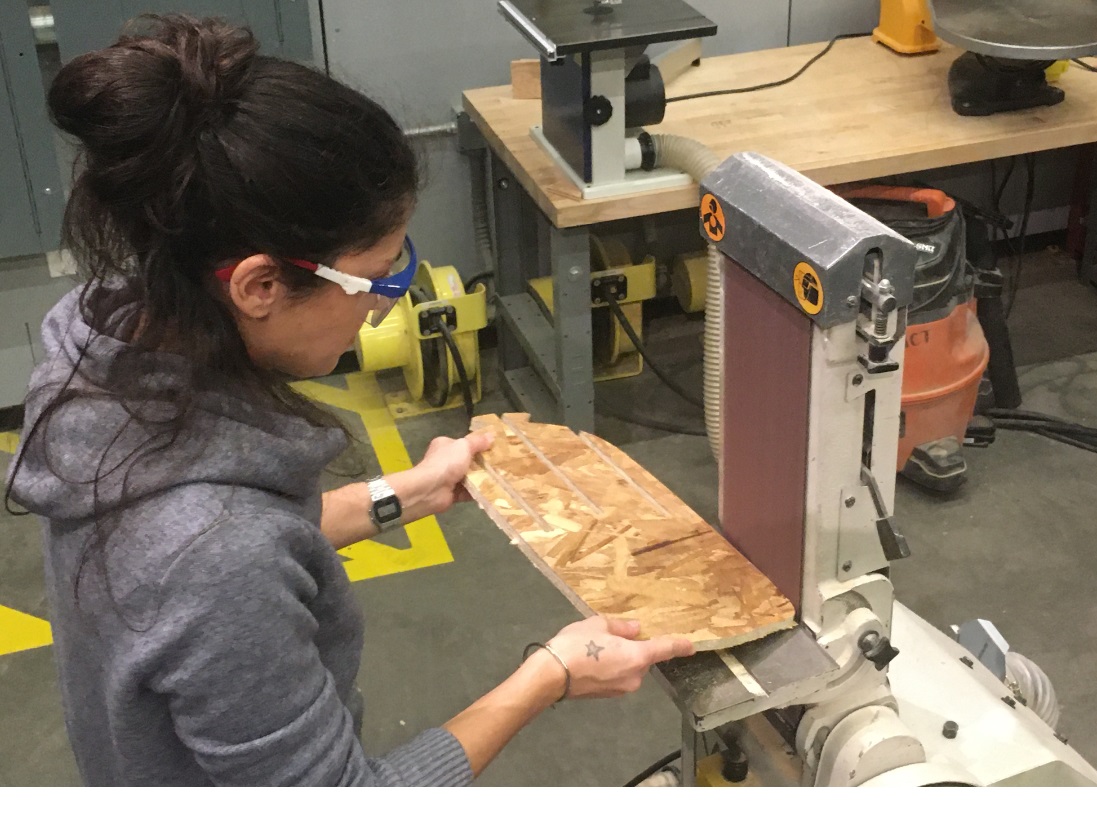
After cutting my parts, I used files and the sander machine to make their edges smoother.
Then, I assembled the parts together and my big fish was ready!