Final Project
~ logbook ~
For her final project, Hannah sets out to build a wearable device that helps people break bad habits such as hair pulling, skin picking, and nail biting.
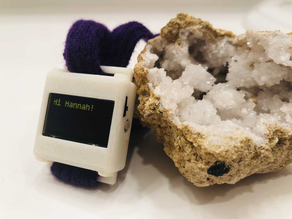
Introducing stopWatch.
the watch that helps you ~stop that~


Q & A
- What tasks have been completed, and what tasks remain?
- I have completed all of the main functionality that I intended to complete–small form factor watch body, screen UI, ability to store new positions, and vibrations when current positions match stored ones.
- Things I would like to do include making an interface on the phone, computer, or watch itself in order to see statistics over time.
- What has worked? what hasn’t?
- Ultimately, I got everything working!
- What questions need to be resolved?
- Battery life. Right now I have a switch that toggles on/off allowing power to flow from the coin cell battery. If I am looking to use this device daily ~12 hours a day, then the coin cell may not cut it. I want to look into the Fullriver battery, which is what the Pebble smartwatch uses, and figure out how the device can be recharged. Furthermore, I would like to explore means of decreasing power consumption by the chip itself via methods like downgrading to the internal 125kHz oscillator (as opposed to the 8 MHz one) and implementing wake/sleep on the OLED.
- What will happen when?
- I am really excited about the final result, and it has already been incredibly useful to me in my daily life for breaking my habits. If I can figure out how to manufacture this in bulk (particularly the case… injection molding?), I will strongly consider moving the project to Kickstarter this summer. I have already had several people ask me for one!
- What have you learned?
- I learned so much completing this project. I’ve gotten much more comfortable using the whole arsenal of design tools available to me. I’ve also drastically improved at board design and debugging (for example, learning how to use oscilloscopes to debug communication protocols). I also learned what it was like to integrate these skills together: to make my final product as small as possible, the case and board needed to be dimensioned matched so that needed to happen in tandem. I also generally feel much more comfortable moving from conceptual ideas to physical things.
Vision
The idea for my final project is something I’ve wanted to make for myself for many years now. I have suffered from chronic skin picking for the better part of my adult life. This habit is something I have tried to break many times before. I have used every technique in the book: logging, fidget toys, gloves, and so on. These generally help for a few months while I am very focused on breaking the habit, but eventually my mind moves on to other things and the habit returns. Part of the problem is that much of the habit is subconscious–I engage in the habit much before I realize (if ever) that I’m doing it. If something could remind me every time I engage, it would be much easier to disengage. This is what I want to build.
The essential idea for the system is a wearable wrist device, equipped with an IMU (the input device) and a micro vibration motor (the output device). When the IMU detects my hand at one of several pre-programmed angle settings (which correspond to several picking positions), the wearable will emit a small vibration, alerting me to stop.
Mockup
Timeline
- November 6: Input Devices – read data from the accelerometer
- November 13: Output Devices – write data to the vibration motor and screen, USB output from ATMEGA
- November 20: On-chip position state programming via button
- November 27: Design and 3D print wearable frame, attach fabric strap
- December 4: IC logic for screen display
- December 11: System integration and finishing touches
- December 16: Masterpiece documentation
Components List
- ATMega328P
- LCD Display (1 in. x 1 in.)

- Vibration Motor (0.28 in)

- Accelerometer (surface mount)

- Machine Knitted wrist-strap
- 3 V Lithium Coin Cell battery (CR2032)
- 1 Button
- 1 LED
Cost of Parts:
[insert table here]
Logbook
Printing Data from Accelerometer to the Screen
~ Continuation from output device week. ~
While Neil has a python script for reading the serial data from the accelerometer, I will need to use that data directly on the microprocessor.
In order to figure out how to do this, I consulted the ADXL343 data sheet:
Register 0x32 to Register 0x37—DATAX0, DATAX1, DATAY0, DATAY1, DATAZ0, DATAZ1 (Read Only)
These six bytes (Register 0x32 to Register 0x37) are eight bits each and hold the output data for each axis. Register 0x32 and Register 0x33 hold the output data for the x-axis, Register 0x34 and Register 0x35 hold the output data for the y-axis, and Register 0x36 and Register 0x37 hold the output data for the z-axis. The output data is twos complement, with DATAx0 as the least significant byte and DATAx1 as the most significant byte, where x represent X, Y, or Z. The DATA_FORMAT register (Address 0x31) controls the format of the data. It is recommended that a multiple-byte read of all registers be performed to prevent a change in data between reads of sequential registers.
Thus to extract the acceleration data directly from the registers, we (1) combine the two registers for each coordinate into one number (2) convert from 2’s compliment to a signed integer.
///ACCELEROMETER
// read and send data
//
data[0] = 0x32; // X0 register
ret = I2C_master_write(data,1,I2C_slave_address_adxl);
ret = I2C_master_read(data,6,I2C_slave_address_adxl);

//calculate accelerometer data for screen display
// data stored LSBX, MSBX, LSBY, MSBY, LSBZ, MSBZ as 2's compliment
// >> is a right bit shift to give MSB
x = 256*data[1]+data[0];
if ((x >> 15) == 1) {
    x = -(0x10000 - x);
}

y = 256*data[3]+data[2];
if ((y >> 15) == 1) {
    y = -(0x10000 - y);
}

z = 256*data[5]+data[4];
if ((z >> 15) == 1) {
    z = -(0x10000 - z);
}

////ACCELEROMETER
//

// convert integer acceleration to string
itoa(x, str_x, 10);
itoa(y, str_y, 10);
itoa(z, str_z, 10);

// print acceleration to serial
put_string(&serial_port,serial_pin_out,str_x);
put_string(&serial_port,serial_pin_out," ");
put_string(&serial_port,serial_pin_out,str_y);
put_string(&serial_port,serial_pin_out," ");
put_string(&serial_port,serial_pin_out,str_z);
put_string(&serial_port,serial_pin_out,"\n");

// print acceleration to OLED
OLED7x8string(2,14,str_x);
OLED7x8string(4,14,str_y);
OLED7x8string(6,14,str_z);
Since this code outputs the three signals through serial, we can not only see them on the Serial Monitor in the Arduino software but also on the Serial Plotter, which gives a nice visualization of the values and how they change as the orientation changes.
Learning Angles
To find the set of wrist positions, the user will press a button and hold their hand in that position for 2 seconds. I will sample at .1 samples/second for those 2 seconds, and compute the average using the online algorithm for computing an average of N samples from a rolling window:
avg_new = avg + (new_sample - avg)/N
        = new/N + avg*(N-1)/N
And as a C function:
int online_avg(int prev_avg, int new_sample, int window_size){
    int new_avg;
    new_avg = prev_avg + (new_sample - prev_avg)/N;
    return(new_avg)
}
Using the code on the acceleration data looks like this:
//update average
x_avg_temp = x_avg;
x_avg = online_avg(x_avg_prev, x, WINDOW_SIZE);
x_avg_prev = x_avg;
y_avg_temp = y_avg;
y_avg = online_avg(y_avg_prev, y, WINDOW_SIZE);
y_avg_prev = y_avg;
z_avg_temp = z_avg;
z_avg = online_avg(z_avg_prev, z, WINDOW_SIZE);
z_avg_prev = z_avg;
I played around with different loop delays (how often the function updates) and window sizes (how many items are in the average). Printing all of the values to the serial monitor like so
// convert integer acceleration to string
itoa(x, str_x, 10);
itoa(y, str_y, 10);
itoa(z, str_z, 10);
itoa(x_avg, str_x_avg, 10);
itoa(y_avg, str_y_avg, 10);
itoa(z_avg, str_z_avg, 10);

// print acceleration to serial and format for serial plotter
put_string(&serial_port,serial_pin_out,str_x);
put_string(&serial_port,serial_pin_out," ");
put_string(&serial_port,serial_pin_out,str_y);
put_string(&serial_port,serial_pin_out," ");
put_string(&serial_port,serial_pin_out,str_z);
put_string(&serial_port,serial_pin_out," ");
put_string(&serial_port,serial_pin_out,str_x_avg);
put_string(&serial_port,serial_pin_out," ");
put_string(&serial_port,serial_pin_out,str_y_avg);
put_string(&serial_port,serial_pin_out," ");
put_string(&serial_port,serial_pin_out,str_z_avg);
put_string(&serial_port,serial_pin_out,"\n");
allows me to view the plots of all 6 values (the 3 axis acceleration and their corresponding averages). It looks pretty good!

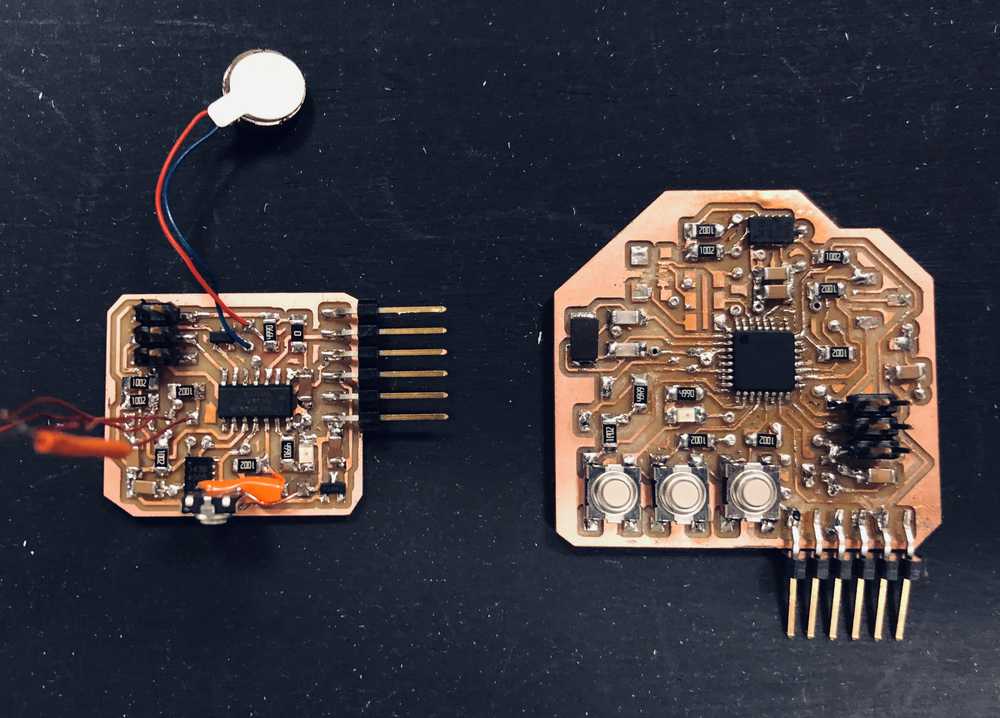
Downsizing the Board
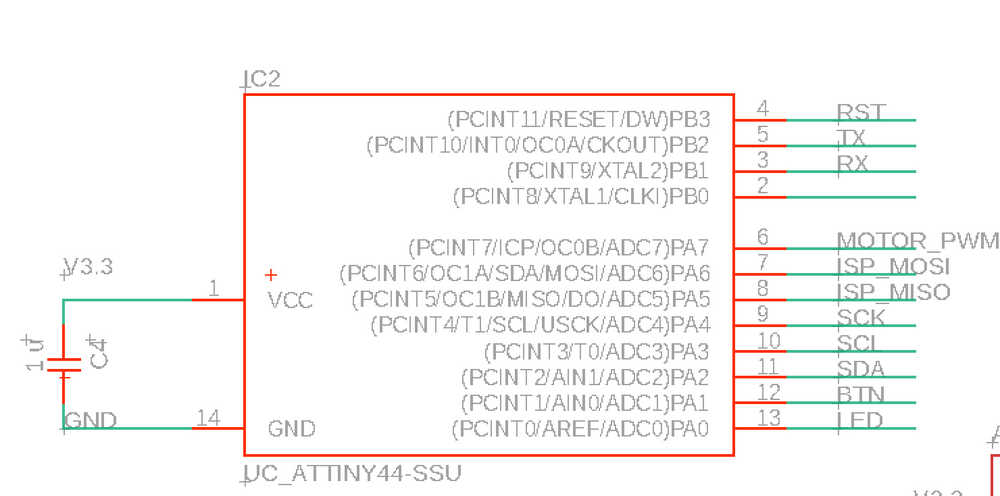
Now that the board has essentially the correct functionality, I decided it was time to pear it down to just the minimum number of components. If I use an internal resonator, one button, one motor, one led, SDA, and SCL, it turns out I can use the much simpler ATTiny44 device.
When hooking up pins, note that SCK, MOSI, MISO, and RST have to be the corresponding pins on the board, but SDA and SCL don’t because Neil’s code does I2C bitbanging.
Final board design reduced from 1.7 inch side length to 1.2 inch, which is a much more comfortable profile for my small wrist.
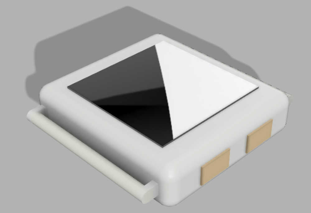
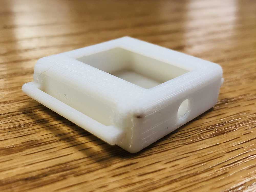
Case Design

I love screwless designs. This meant I could do snap fit or press fit. Since I had devoted week 3 to making precisely this–a snap fit box with a lip–as much as I wanted to play around with PLA press-fit, I decided to go with the design parameters that I already know work.
For the first iteration, I gave some leeway with all the parameters to make sure at the end of the day I will at least have something that fits all of the components. Further iterations will be devoted to streamlining the case to be as small as possible. Furthermore, this first prototype will help me get a better sense of how to organize all the components inside.
As expected, the first prototype, which came out of the uPrint 45 minutes later, was a success.

Programming
Debugging
First, I tried the blink code with the new pins to get a sense of what worked on the board. Sure enough, it failed to program.

Knowing that the only pins related to programming are MISO, MOSI, SCK, RESET, GRD, V3.3 (the ISP pins), I checked for
1) Voltage regulator generating 3.3 V from 5 V? 2) Short from power to ground? 3) MISO, MOSI, SCK, RESET are the correct pins on the ATTiny44 4) Shorts between the ISP pins?
And, sure enough, RESET and SCK were shorted! I found the source of the short, fixed it, and the blink program loads perfectly now.
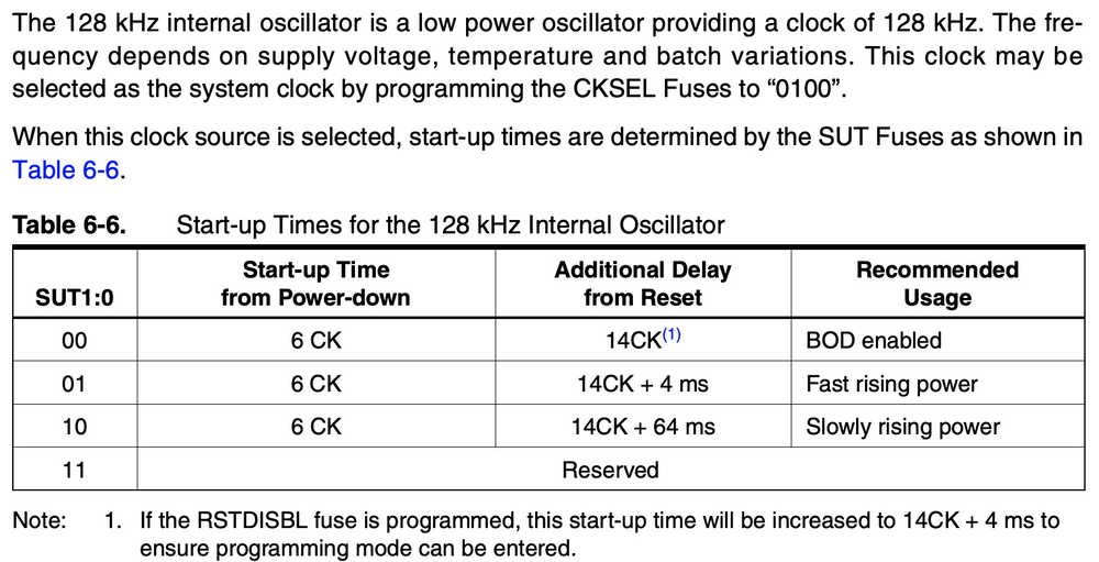
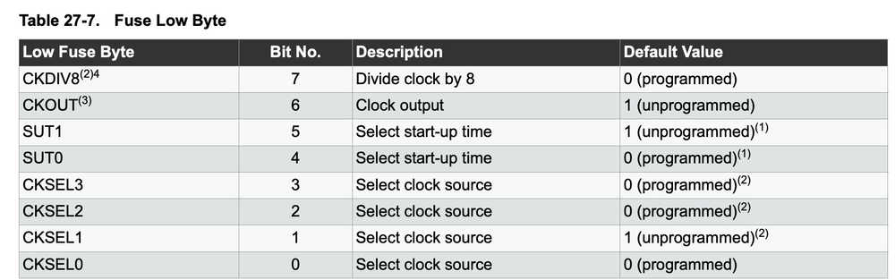
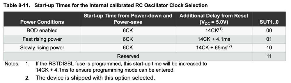
Fuse Bits
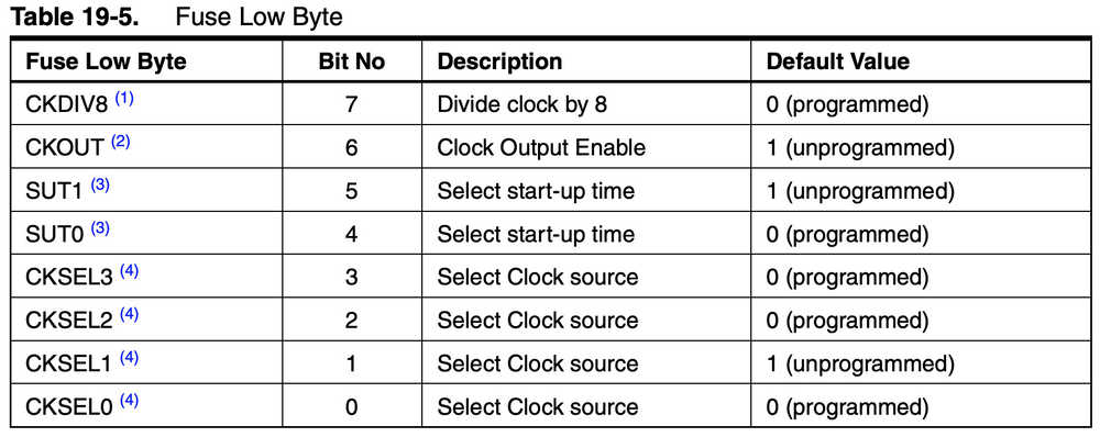

The SUT bits for the internal 8MHz RC oscillator and lower frequency internal 125kHz oscillator are shown below:

Note for all fuses, “0” = programmed “1” = unprogrammed
Thus our low fuse byte should look like:
CKDIV8 = 0 for programmed
CKOUT = 1 for unprogrammed
SUT[1:0] = 01 for fast rising power
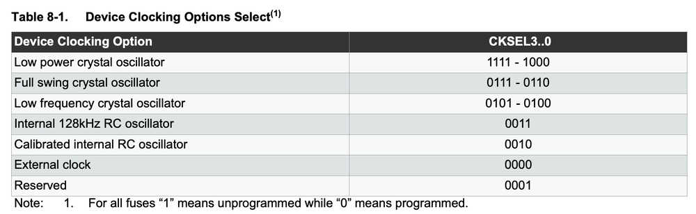
CKSEL[3:0] = 0010 for 8MHz internal oscillator
Low Fuse Byte: 0b01010010 = 0x52
Testing Serial Communication
As with when I started programming the ATMega16U2, at a baud rate of 115kb/s, I was seeing garbage. Unsurprisingly, the same thing happened again here. I suspect the reason is that I’m using a slower clock than the original ATTiny44 board from week 4 and 6 that had an external 20 MHz resonator. For reference, I uploaded a simple code to print “0123456789…”
Here’s an example of the gibberish received through FTDI:

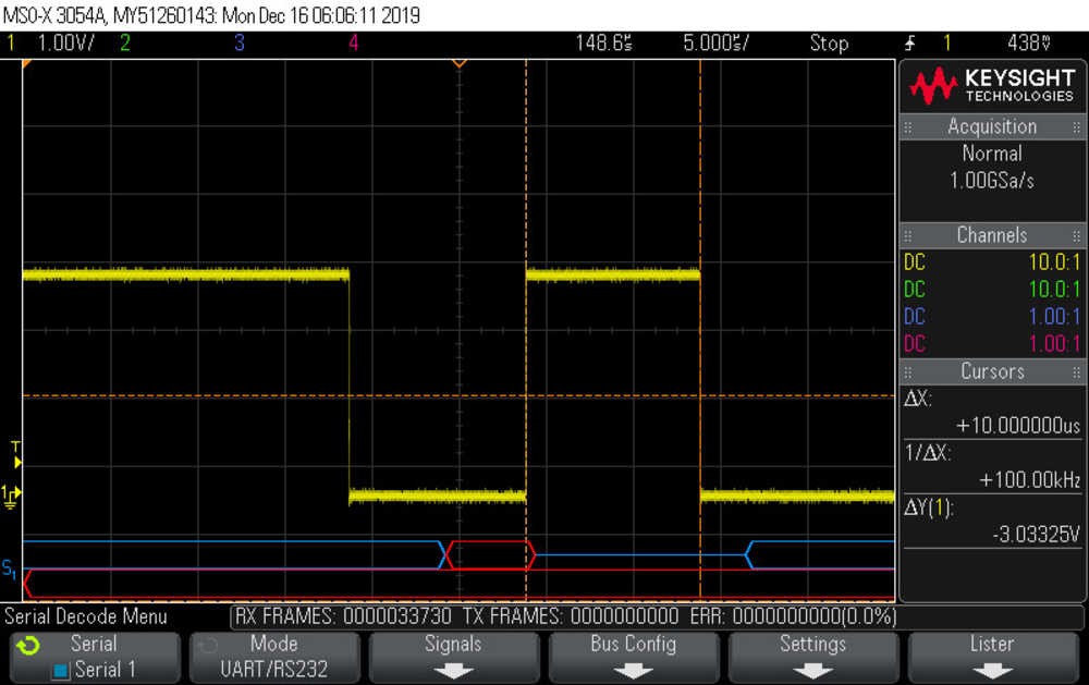
I solved this problem the same way I did with the ATMega–using the UART decode mode on the MSOX3054A oscilloscope.
Here’s the measurement of a small peak; the scope decodes at a baud rate of 100 kb/s.
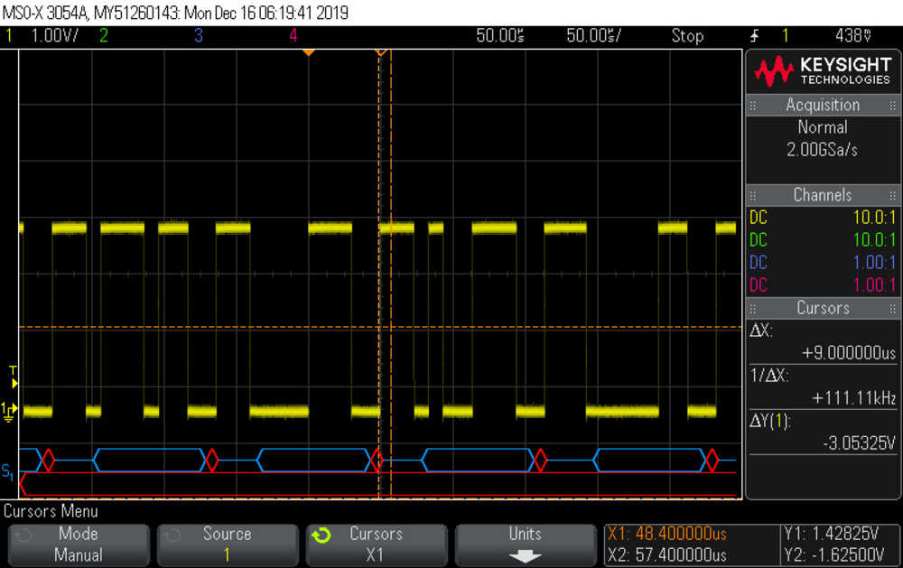
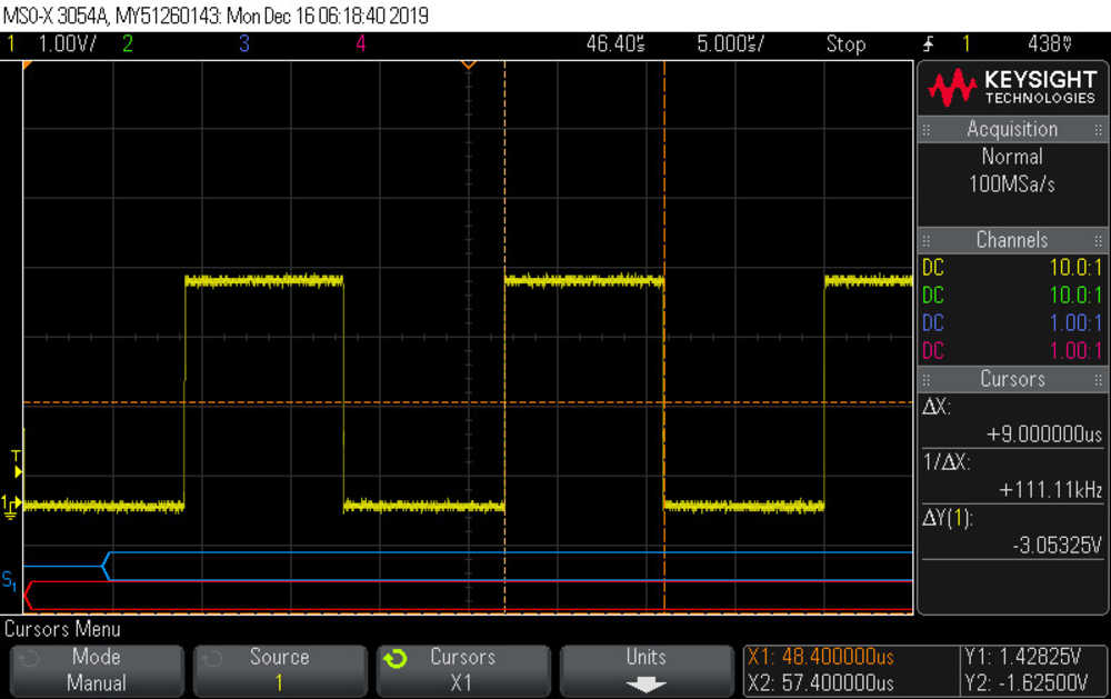
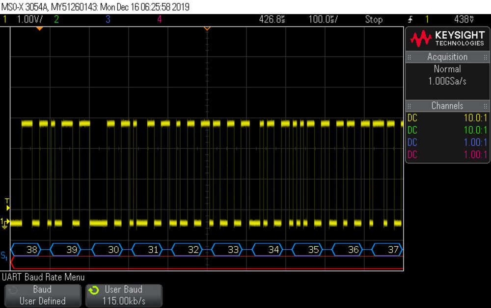
And here’s the measurement with the bit_delay variable changed from 8.5 to 7.5. The scope decodes at 115 kb/s and the serial output is now correct:

Finally, since ultimately I will transmit the acceleration data at 9600 bits/s, I checked that changing the bit delay to 1⁄9600 = 103 micro seconds would correctly be received by a baud rate of 9600, which it did.
Checking the Basic Script
And….. I’m out of memory :(
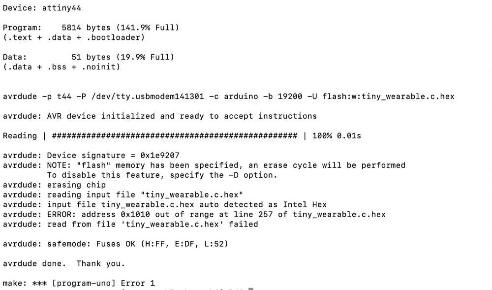
So apparently, the program as it is now needs 5184 bytes of flash memory to store the program. Here are some specs of various microcontrollers:
ATTiny44 - 4K Bytes
ATMega16U2 - 16K Bytes
ATMega328P - 32K Bytes
So… given that I haven’t implemented the state machine, looks like I’ll be selecting the ATMega328P. Time to mill a new board!
328P Basics
A few basics about the 328P are that
1) the Make file will refer to
m328p
MMCU = atmega328p
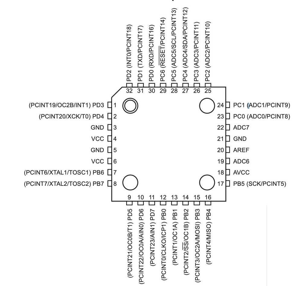
2) The pinout:
3) Fuses:

So for an 8 MHz internal clock with fast rising power we will want 0b01010010 = 0x52 (Which is the same as the bits for the ATTiny44).
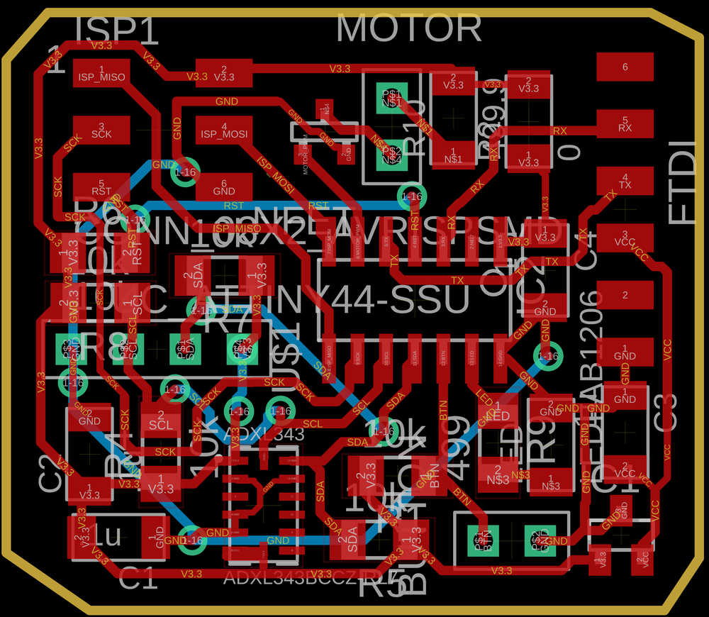
Mega328P Board Design
I’m actually really proud of this board. I think I’ve gotten a lot better at board design to the extent that this was a single sided board (the tiny44 and m16u2 based boards were both double sided) and it was still smaller than the previous ones!
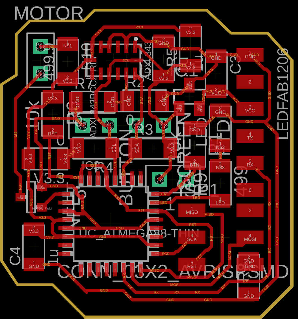
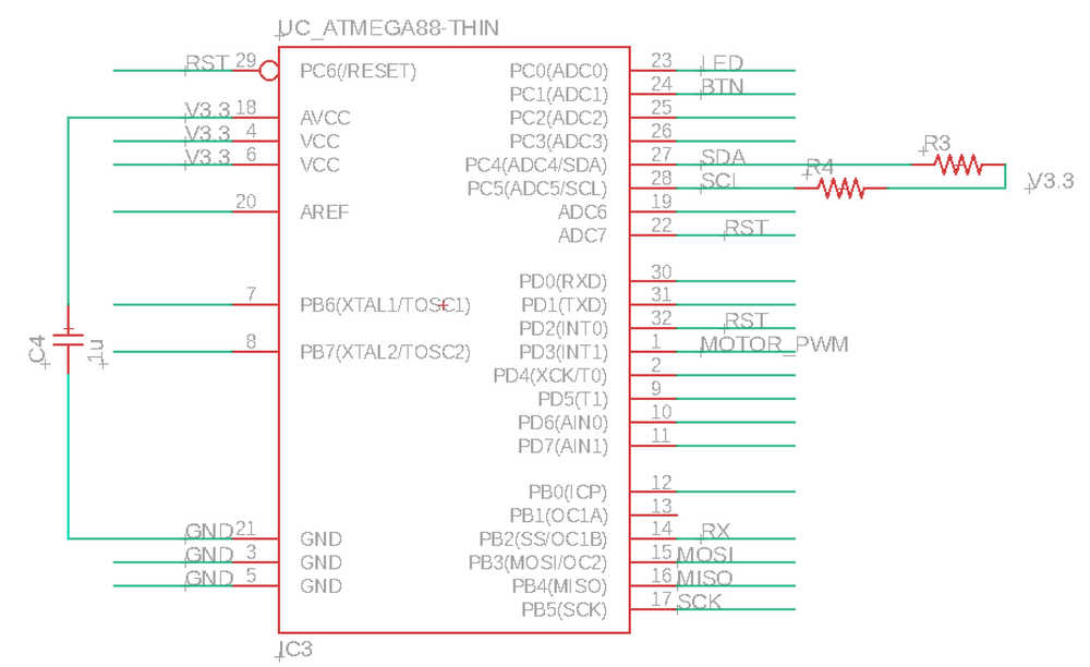
SDA = PC4
SCL = PC5
RX = PB2
MOTOR = PD3
LED = PC0
BTN = PC1
*note: RST = PC6 for real, but soldered ADC7 and PD2 as well, those should technically be turned into input pullups so that there is no voltage conflicts. Since RST is only used during programming however, this probably doesn't matter too much.
State Machine for Device Operation
The following image is a representation of the internal FSM that controls the GUI and device response.

Telling Time
After drawing out the state machine, I realized I was going to want a way to tell time (in particular, to figure out how long buttons have been pressed for, etc.)
The avrlibc library apparently does not include time.h C library, so I found the source file for it, downloaded, added it to the directory with the code and make file, and ran make… nope.
/var/folders/q5/_tzh7dyn0x9d42p89sxjmfm00000gn/T//cc9x4fFM.o: In function `main':
328p_wearable.c:(.text.startup+0x7e): undefined reference to `time'
328p_wearable.c:(.text.startup+0x90): undefined reference to `time'
328p_wearable.c:(.text.startup+0x98): undefined reference to `difftime'
After some googling, it turns out that to use a .h file, I need to include that information in my make file (makes sense, since it could have been a .h file that I wrote myself).
I also found a helpful tutorial with some examples of using it.
The following lines are all I need for my program:
time_t press_time, current_time;
press_time = time(NULL); //gets time
.... delay ....
current_time = time(NULL); //gets time
difftime(current_time, press_time)); //returns number of seconds elapsed as a double
Well, after a bunch of research and discussion wit Alex, it seems like this will be quite difficult. I’ll need to write my own interrupt function based on the system clock that runs at 1 Hz so that the counter can count. A feature for another time. This means I’m back to using an integer count up.
Button FSM
The basic working button FSM has three states: UNPRESSED -> SHORT_PRESS -> LONG_PRESS. I tuned the counter and found that counting to 80 was a satisfying amount of time for “long press.”
Haptic Feedback
I then implemented a haptic feedback function with a variable number of pulses and tuned it until I found a satisfying number for VIBRATE_DELAY (100)
void vibrate(int reps){
    int i;
    for(i = 0; i < reps; i++){
        set(motor_port, motor_pin);
        _delay_ms(VIBRATE_DELAY);
        clear(motor_port,motor_pin);
        _delay_ms(VIBRATE_DELAY);
    }
}
I intend to use:
- 3 pulses to signal calibration mode start and stop
- 2 pulses to signal the user hand position match
GUI and OLEDs
The main thing I learned in implementing the GUI is that the screen takes a while to update. So, if the entire screen needs to be updated every time the state machine matches a certain case, that will dramatically slow down the loop. The result of this was that the accelerometer data was updating way too slowly. An additional effect was that even with the button press counter set to 1 or 2, the long timing of the loop made it only recognize the button press after an unreasonable amount of wait time.
Why was I updating the entire screen ever anyways? Well, to display new things on the screen and have old things on the screen clear, spaces need to be printed to every pixel. This takes a while. On the other hand, updating just a few pixels live is very quick (e.g., live-displaying the position coordinates is fine.)
The main place this hurt the system was in maintaining the home screen as saying nothing but “Hi Hannah.” So to fix this I added a “STARTUP” state that would clear the screen and then immediately move to the “HOME” state.