Week 1
~ cutting ~
This week on HTMAA: Hannah learns how to use the laser and vinyl cutters. Using these new skills, she creates a replica of the George Washington Bridge using a custom made laser-cut construction kit.
Laser Cutter
Characterizing Properties of the Laser Cutter
- Power
The laser cutter in EDS has a max power output of 75 W. We are however able to change the device setting to be lower. One way to penetrate more or less deep into a material is to adjust the laser power, although speed rather than power is the preferred method.
- Focus
This step is a must. We want to align the narrowest point of the laser beam (where the power concentration is greatest) to the surface of the material we are cutting. To do this we can adjust the vertical position of the laser. Thankfully each laser cutter comes with a tool whose height is calibrated to the laser properties, making this process pretty easy.
- Speed
The slower the laser moves during a cut the more time it spends blasting energy into each little area… the “deeper” the cut.
- Rate
How many times the laser goes back and forth.
- Kerf
The laser beam has a non-negligible diameter. The location of the “cut” represents the location of the center of the laser. What this means is some material will be removed on either side of the cut location, changing the resulting dimensions of cut piece from the ones dictated in the drawing file.
- Joint Clearance
When a joint is formed by two cuts, you need to take into account Kerf for to ensure a snug fit.
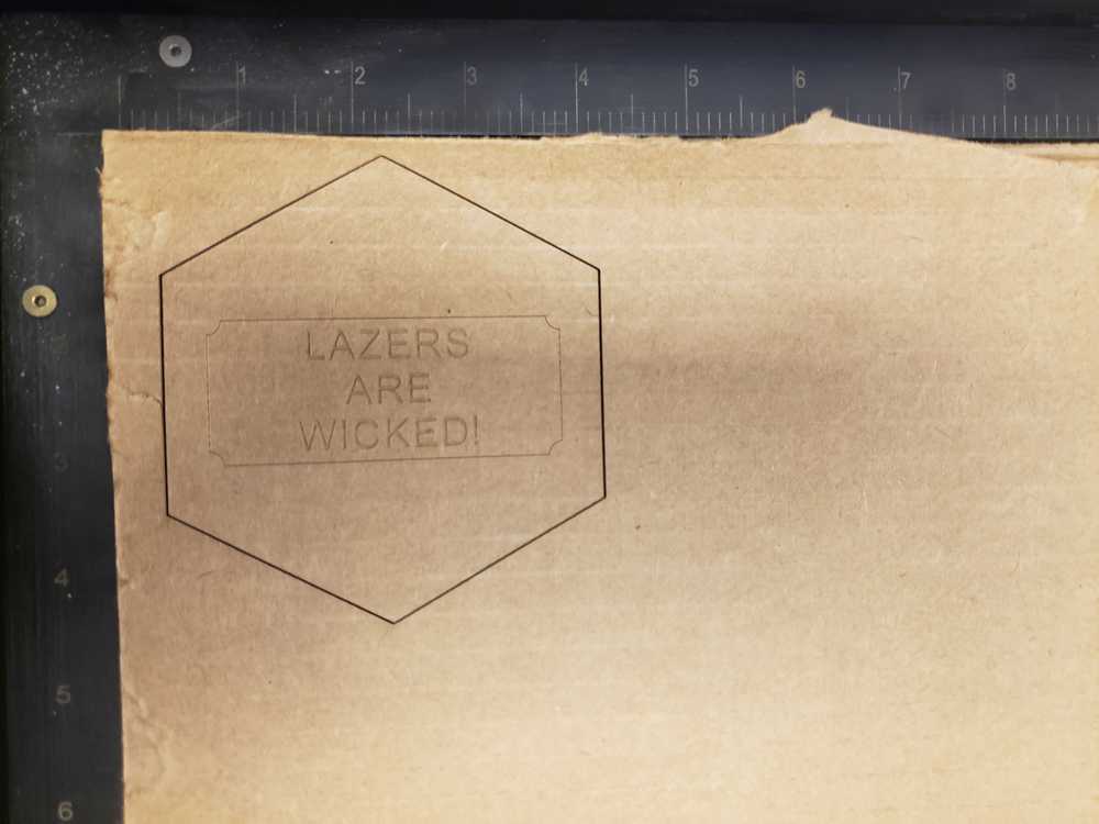
Group Work
Our group met on Friday to begin to learn how to use the laser cutter. After a training from Anthony, we dove into the settings and attempted to cut a basic design we drafted in CorelDRAW onto a piece of cardboard. We measured our cardboard to be 0.1675 inches thick. Since the cardboard is pretty flimsy, as a starting point for the laser settings we used those for Balsa (a very thin wood). As is, it worked pretty well, although in some areas the cut did not penetrate through the entire material. To remedy this, on our second attempt we decreased the speed from 16% to 13%. This was good! Laser cutting demystified!
Laser-Cut Construction Kit
Ever since I can remember, I have been obsessed with the George Washington Bridge, a stunning suspension bridge connecting upper Manhattan and New Jersey. It has been the focus of my artistic attention many times before.
So for this week, I will pay respects to this masterful bridge by building a mini replica. I found this online source to aid in dimensions of the structure https://www.ce.jhu.edu/perspectives/studies/George%20Washington%20Files/GW_Geometry.htm
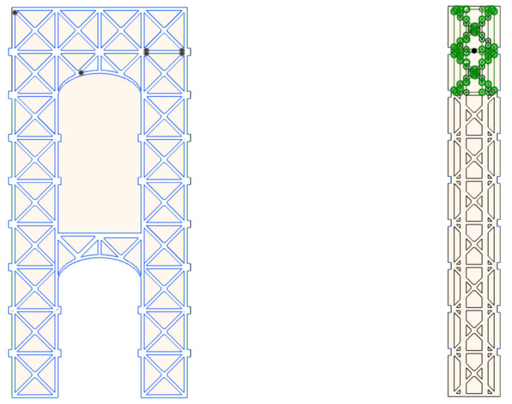
This is my first time working with 3D modeling software (Fusion360 in particular), so the learning curve was a bit steep. It was an interesting mental exercise. Usually when I build something, I draft a couple images on paper with their dimensions, and usually it just comes together. It was an entirely different experience to explicitely define every single length parametrically and to specify all relationships and constraints–even the ones that seem obvious. My major takeaway from the experience was that taking the time to make sure pieces are exactly correct in the first place (that somehow an edge didn’t get dragged such that a length is not precisely what I thought it was) will save a LOT of time and frustration later on down the line. In particular, after many hours of struggling to make two pieces fit together because the distances were a little bit off, I finally just started from scratch, which was much faster after having a better understanding of what I wanted to do. I think in the future I will do more of the drafting on paper before moving to the 3D modeling software.
Here are the pieces I made:

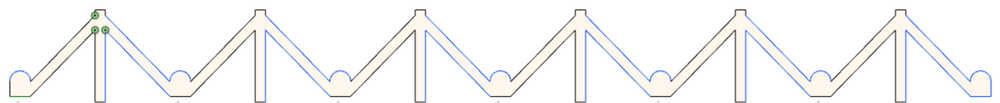
The really frustrating aspect was that when I imported the DXF ile to CorelDraw, all the construction lines still appeared, so I had to manually go and delete them. I ended up having to do several iterations of printing the bridge so to save time I eventually went in and deleted the construction lines from the original CAD drawing. Furthermore, CorelDraw doesn’t like ellipses (which was how I designed the bridge archways) so I had to redraw those in CorelDraw every time I wanted to print. Overall, the pipeline was very time consuming.
First pieces coming out of the laser cutter:

So… the first attempt didn’t work so well. As you can see in the image below, the joints are coming apart–they were too loose. It was barely stable enough to take a photo of.
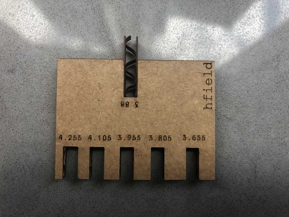
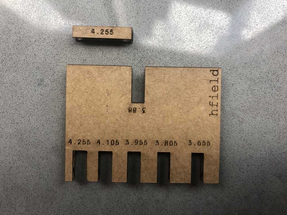
Basically, I didn’t properly account for the kerf of the laser. So I went back and made something that I should have simply made at the beginning–a handy dandy kerf tool. The width of the cardboard was 4.3 mm and I found that the 3.9 mm insert joint was a proper match meaning that the kerf (the amount of excess material the laser cuts out) is about 0.4 mm.
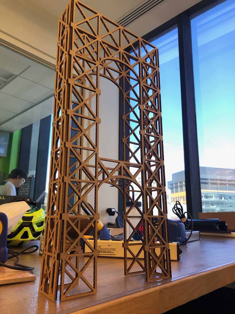
I had to redo most of my CAD drawing in order to be able to change this parameter (since I had deleted the construction lines and constraints in order to print from CorelDraw; I will definitely separate the two versions in my pipeline in the future). But good news, the new version worked! It was so satisfying to listen to the sound of the joints pressing together, meaning they had a nice tight fit.

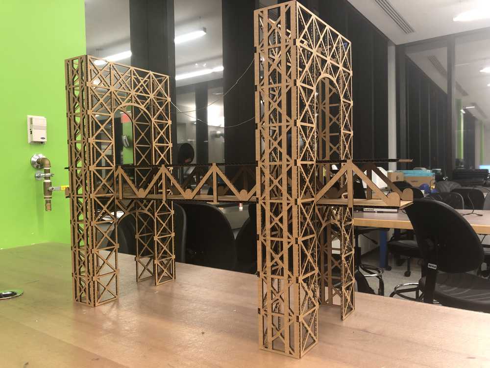
Overall, I’m pretty content with the way this came out. Two things I would like to change are (1) the height of the roadway; I want it to better match the complexity and size of the archway pieces and (2) add the suspension (which right now is being represented by some strands of solder).
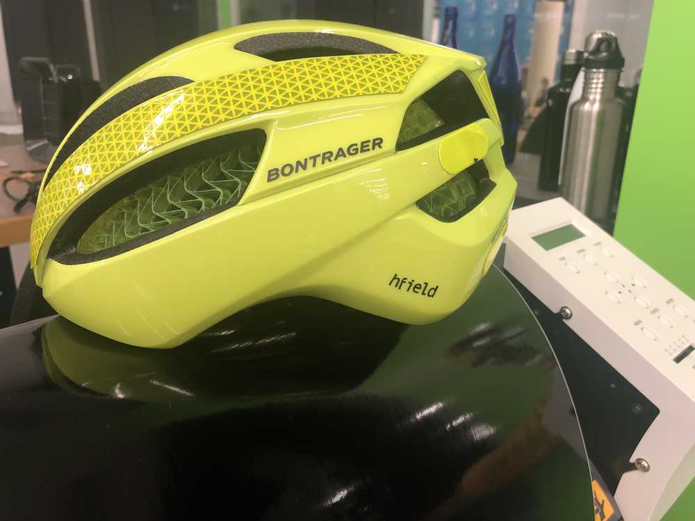
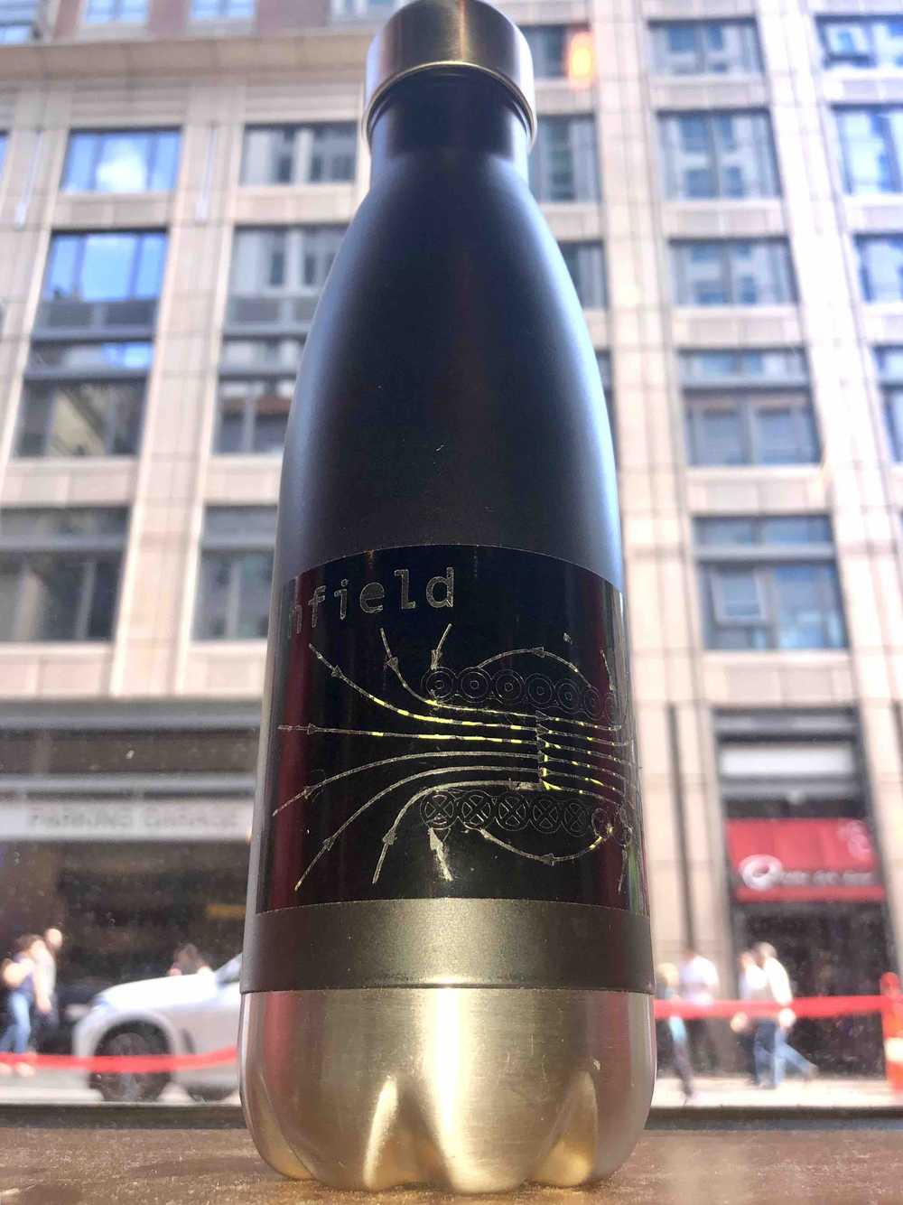
Vinyl Cutter
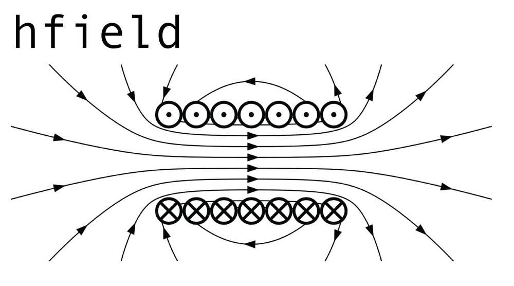
My kerberos–hfield–is tremendously fitting as a physics major. So, for my vinyl cutout, I thought I would do my kerberos justice and really drive home the pun. I drafted up the following image:
And here is what the vinyl cutting software thought about it:
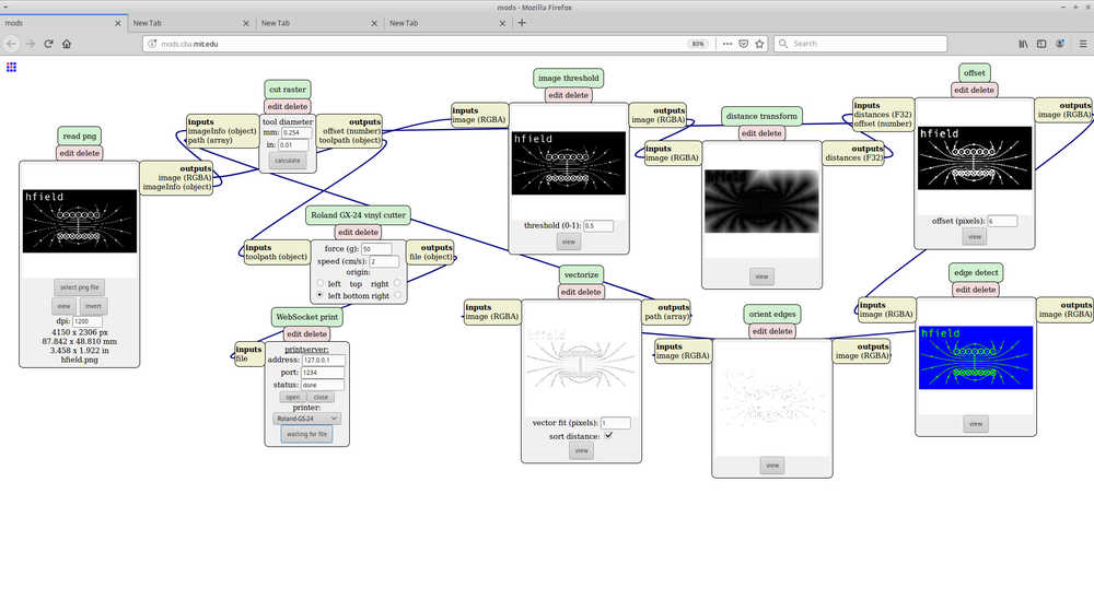 Note, the image is inverted from the original.
I quickly learned a few things:
- The image needs to be in black and white–no invisible background.
- The algorithm for the cutting path attempts to “cut out” the black region. Since my image has only very fine lines, the program was not able to detect them for inclusion on the cutting path. It turns out (thanks Ben!) that you can trick the algorithm by inverting the colors so that the regions the algorithm looks to “cut out” are the large one. This inversion makes no difference for the final transfer since I have the ability to remove whatever vinyl I want.
- The letters in my name were so narrow that it was actually much easier to peel out each letter from the vinyl and transfer one at a time to the mounting surface than it was to peel away the excess material (which was almost everything).
Here are the final results!