Week 5
~ machining ~
This week on HTMAA, Hannah learns to use the router to make something BIG. Using nothing but a single 4 foot by 8 foot sheet of OSB, she creates a custom standing desk that can easily be assembled and disassembled.
The Design
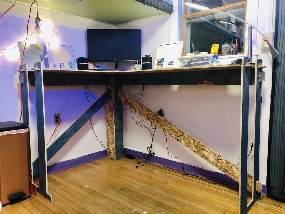
I have been craving a bigger desk for my room for quite a while now. I just moved to a new home, so I haven’t been able to fix it up exactly to my liking just yet. A few years ago, in an old room, I made a big corner desk out of a 4 by 8 foot piece of wood cantilevered to the wall. Because I attached it to the wall’s molding, I didn’t have any control over its height. I used a hand-held jig saw to cut the curve between the two sides. As I learned , this doesn’t work very well. The cut was incredibly jagged, and even with copious amounts of sanding it couldn’t be fixed. So, for this week’s assignment, I thought it was time to redo that old desk and give it everything it once didn’t have. This time it will be a big, beautiful, standing desk with dimensions to fit precisely into the corner of my room.
Before beginning to CAD, I sought out inspiration from previous HTMAA students. Eventually I found an elegant and sturdy looking version from Josef Paul. I am particularly intrigued by his joints, where the pieces slide together and use a small insert hammered in to lock everything in place.
Assembly in CAD:
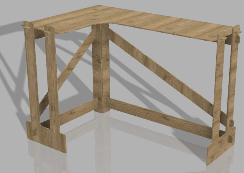
Rendering:
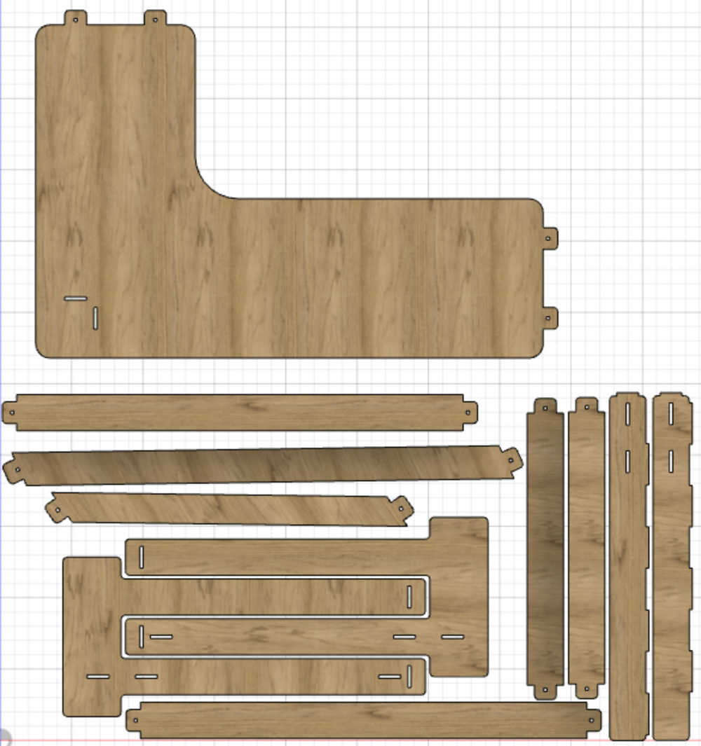
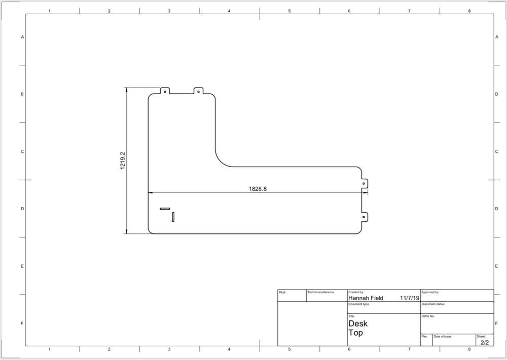
Layout of pieces on 4x8 ft. rectangle:

Converting to MasterCAM
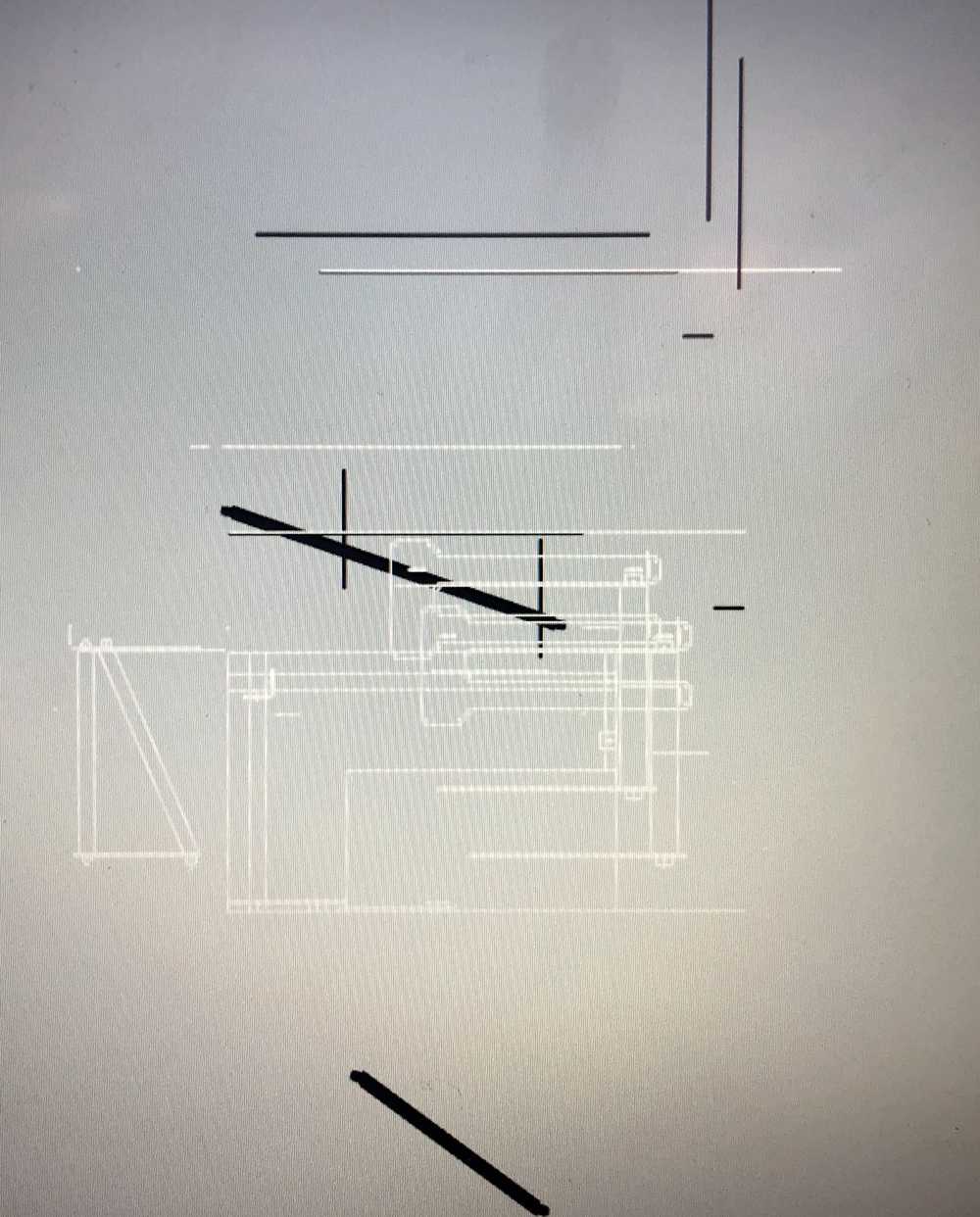
In the process of moving from Fusion to MasterCAM, there were LOTS of problems. The first time I exported my files to DXF and opened them in MasterCAM it was a disaster:
Basically, the way creating “components” in Fusion works is such that bodies are constructed in a way related to other existing bodies in the CAD. So when we imported the DXF, all of the bodies and sketches referenced by the final pieces showed up as well.
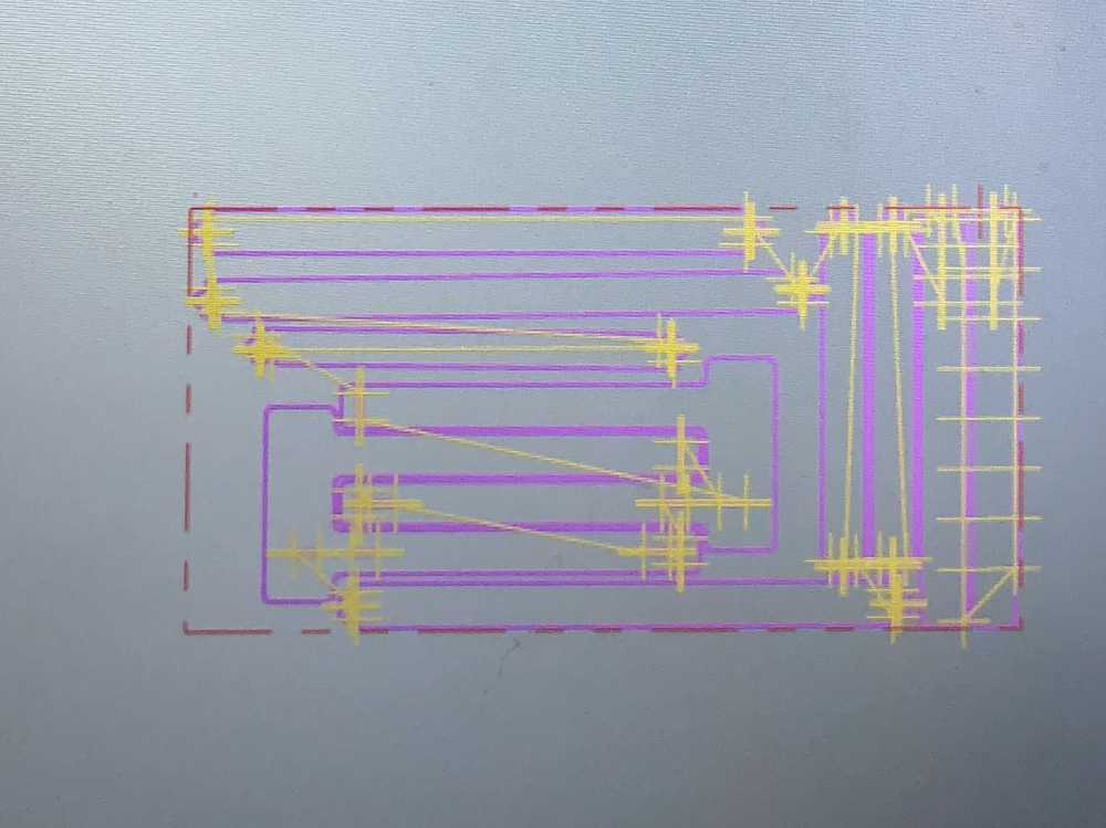
After a while of playing around with things, I figured out a fix: to create a “drawing” out of the model in Fusion (specifically a “projection drawing”) and export the drawing to DXF. This worked! I am really excited about this solution since the import removed all of the construction lines, etc. This would have saved me a BIG headache when using the laser cutter. There, the imported DXFs in CorelDraw contained hundreds of tiny construction lines that were a nuisance to remove. Glad to finally have a solution! Here are the drawings:

and PHEW it finally imported properly:

The plus signs at corners in the above images are part of step 2 in the section below.
Creating the Toolpath
Define the stock (OSB sheet) properties X, Y, and Z (off the bed) distances as well specifying the location of the origin for the cut.
Wireframe: at every internal point, define a point so that can use the drill tool to “drill them out.” This is necessary so that the end mill will actually remove enough of the corners so that pieces fit together.
Router toolpaths -> drill
Contour on inside features on inside of lines
Chaining (selecting edges) - climb so that if endmill spinning clockwise then if traveling up we make the cut on the left side of the material
Feeds and speeds: plunge at half of your feed rate
Depth of cut (-.03 in.)
Repeat, but for outside cuts. Turn of depth cuts. Depth of cut-.01 in)
When get to the shop, check the parameters and tool library before exporting to gcode.
Using the Router
I headed over to the Architechture shop in N51, and Zain helped me get set up with the CNC Onsrud. The first step was to check the tool parameters and change the three tips of bits that the Onsrud will use. The Onsrude is a really cool machine. It has 12 tool slots and can do automatic tool chagnes during the process. We used three tools:
Standard Drill .125
.25 Downcut
.375 Flat Compression
We loaded the Onsrud bed with the sheet of OSB and turned on the vacuum, which flattens the sheet and holds it in place on the bed. Just in case, we taped all of the corners of the wood to the bed.
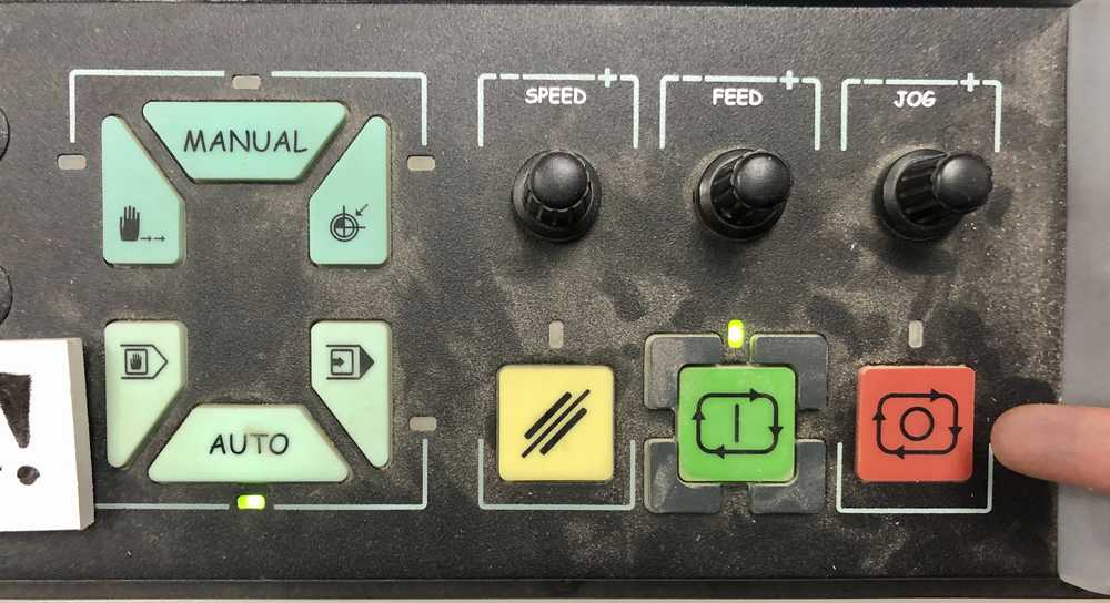
Zain made sure to point out the emergency stop button, which we would make use of in case some small pieces started flying away or moving.
After removing the pieces from the bed, it’s time for cleanup!

Putting it all Together
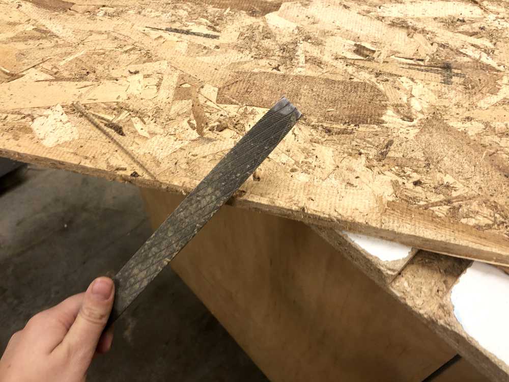
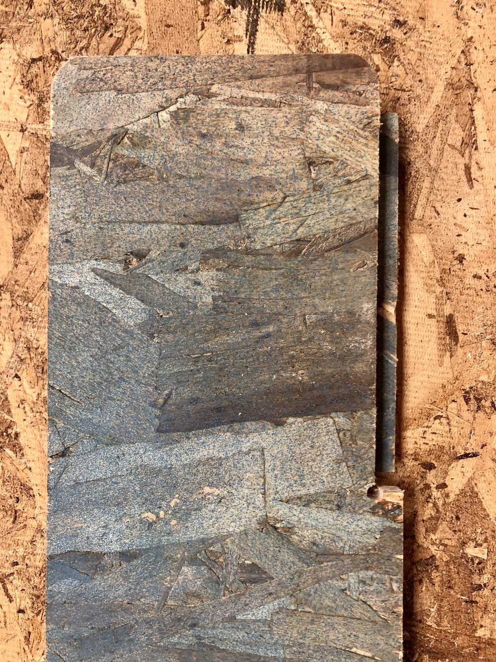
First I had to remove the onion skins. For this, I used a file and went around all of the edges:
Then for some strange reason, the inner support interlocking joints were completely misaligned in a very haphazard way. So I had to sand them a lot until they fit:
Furthermore, due to variations in the thickness of the OSB (as Anthony says, “I thought I left OSB back on the farm.”), even though I left 1/10th of an inch of clearance on all sides of the joints, some of them had to be manually sanded down even further.

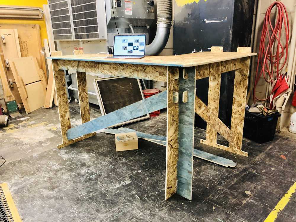
I ended up assembling piece by piece and sanding joints if they wouldn’t fit. After a few hours of this… the desk came together!
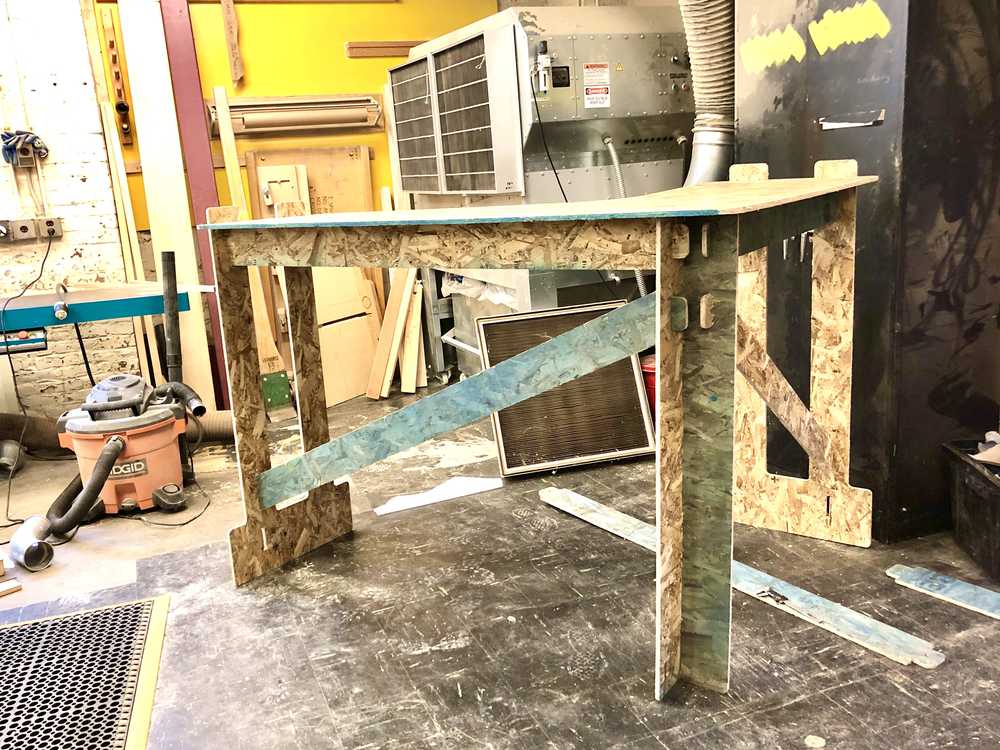
But… something was terribly wrong. Not only did everything FEEL big (and of course this was in fact make something big week) but everything WAS big. So big, I could barely get my elbows up on the table!
After a quick measurement I realized my error. When I had measured the desk for my CAD model I had written down “40” on my drafting paper… 40 for 40 inches. Unfortunately when I went to parametrize the model I entered 40 as 4.0.. that is 4.0 feet. Thus the actual physical desk in front of me was a whole 8 inches too tall! Oy vey.
Since the OSB was rationed out to one per person (and I had already gotten one extra anyways) it didn’t seem like I would be able to re-route the design with the correct parametrization. Furthermore that would require redoing toolpaths, and the arch staff were already quite busy. So, I decided that the best option was to simply hack off as much of the bottom of the desk as possible.
The bottom connected pieces between the legs were 8 inches tall, but if I removed them, the individual legs would be floating, and I got the feeling that it wouldn’t be very stable this way and probably likely to break. Thus I decided to take off 6.5 inches so that there were 1.5 inches of material connecting the legs. This was a happy medium, and although the desk was slightly taller than I would have liked, I decided I could always use a mat on the ground anyways.
Time to tablesaw!
Much better now:
Joints
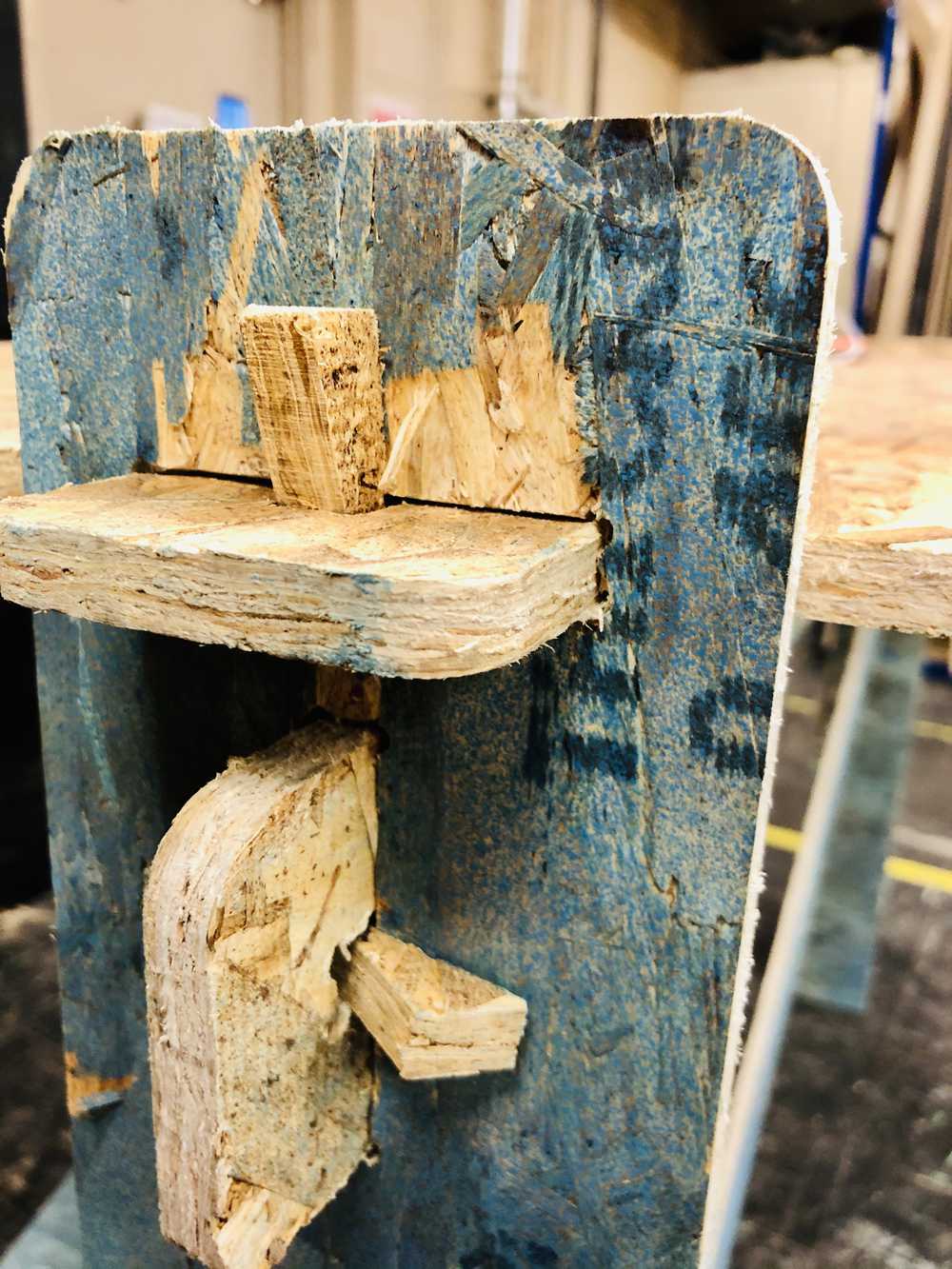
I used the band saw to cut small angled pieces to serve as the wedges. It took some practice to figure out the optimal way to cut these pieces out of the scrap OSB efficiently.

While still in the arch shop, I tested out a few of the wedges by hammering them in. They are very sturdy indeed! It takes a bit of work to get them out, but the desk can indeed be assembled and disassembled at will. This desk has indeed re-affirmed my love of screw-free design.
The Final Desk
I excitedly transported my desk home, assembled it, and hammered in all of the little wedges. The final product looks great, and is super sturdy! It fits right into the corner I designed it for.