Week 8
~ input devices ~
This week on HTMAA, Hannah learns how to interface between an ATTiny and a MEMS accelerometer. This is the first step of her final project. Note: Week 9 includes a more in-depth look at the accelerometer as well as a board of my own design.
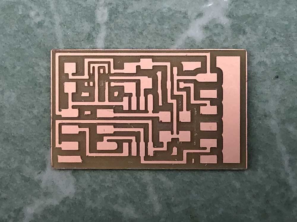
Step 1: Milling and Stuffing the Board
I am using Neil’s prototype board for an accelerometer:
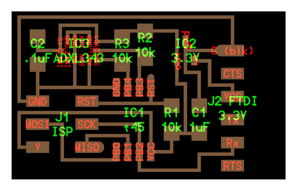
One thing to note about the board is that the accelerometer cannot run at more than 3.6 V, requiring a 3.3 V, 100 mA LDO voltage regulator. Thus, except at the VCC pin coming from the FTDI-USB connection which will contain 5V, the other “V” traces all contain 3.3 V since the ATTiny45 can run between 2.7 - 5.5 V.
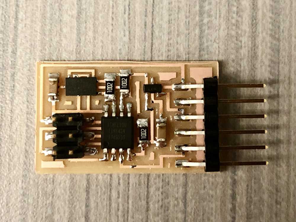
The accelerometer is a very small component with its connections underneath its body. In order to attach that to the PCB, Anthony showed me how to use solder paste and hot air. Next time I use hot air, I will turn the fan speed down since the other components on the board (that were already soldered) started floating away.
Unfortunately the first time I tried to plug in the device to the FTDI to USB, it started getting really hot. There were no shorts, but it turned out I had added the ATTiny in backwards. Lesson learned: don’t match the component direction to the text direction in the diagram: match the pin-out diagrams. After re-soldering, I had the following:
Step 2: Programming
Step 3: Reading Accelerometer Data
To run the python program to see the incoming processed data, first we need to identify which serial port the ATTiny is using. Run the following command:
ls /dev/tty.usb* (for Mac)
ls /dev/ttyUSB* (for Linux)
which produced
/dev/tty.usbserial-FTAMEG07 (on Mac)
/dev/ttyUSB0 (Linux)
Thus when calling Neil’s python program to graphically output the data, you would call it as
python hello.ADXL343.py /dev/tty.usbserial-FTAMEG07 (Mac)
python hello.ADXL343.py /dev/ttyUSB0 (Linux)