Week 2
~ milling ~
This week on HTMAA, Hannah learns to use a mill to create custom traces on a PCB board, ultimately making a programmer, which can load programs onto the embedded processing unit onboard electronics she will make later on.
Using the Mill
The steps to using the mill are as follows:
Insert either the 1⁄64 bit if milling traces or the 1⁄32 bit if milling the outline, and insert the bit all the way up so that when the mill starts up and moves it won’t collide with the PCB.
Tape down the PCB and press it flat against the bed.
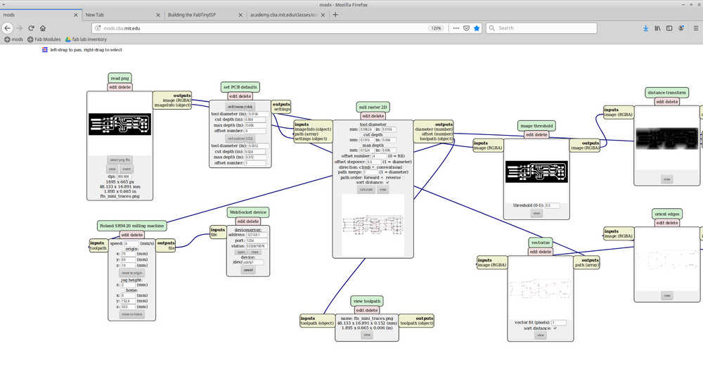
Upload the png file of the design to the mods application, click calculate, and move the end mill to the origin. Adjust the origin coordinates so that the end mill is at an appropriate location for the start of the PCB design. Record the origin coordinates so that you know where to cut out the outline, which is done later.
Loosen the screw on the end mill and gently press it down into the PCB. Good contact pressure between the end mill and the PCB is vital for the success of the process.
Send it off!
The mods software is really easy to use:
Here is a closeup of the end mill packaging. Be careful to make sure the bit inside is the correct size! It is possible the can get mixed up.

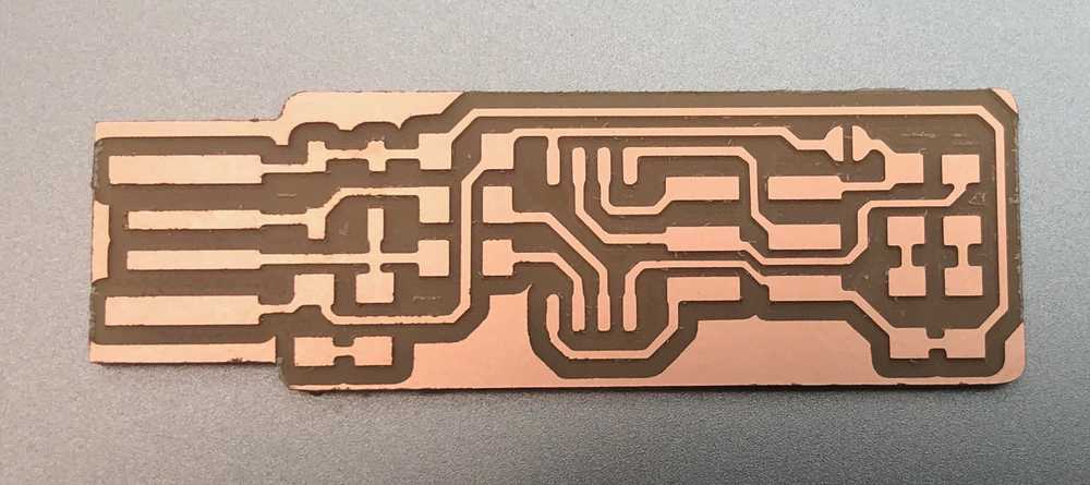
For this week’s assignment, I will follow the design by Brian to create my programmer. The PCB design looks like the following:

My milled board came out very nicely:
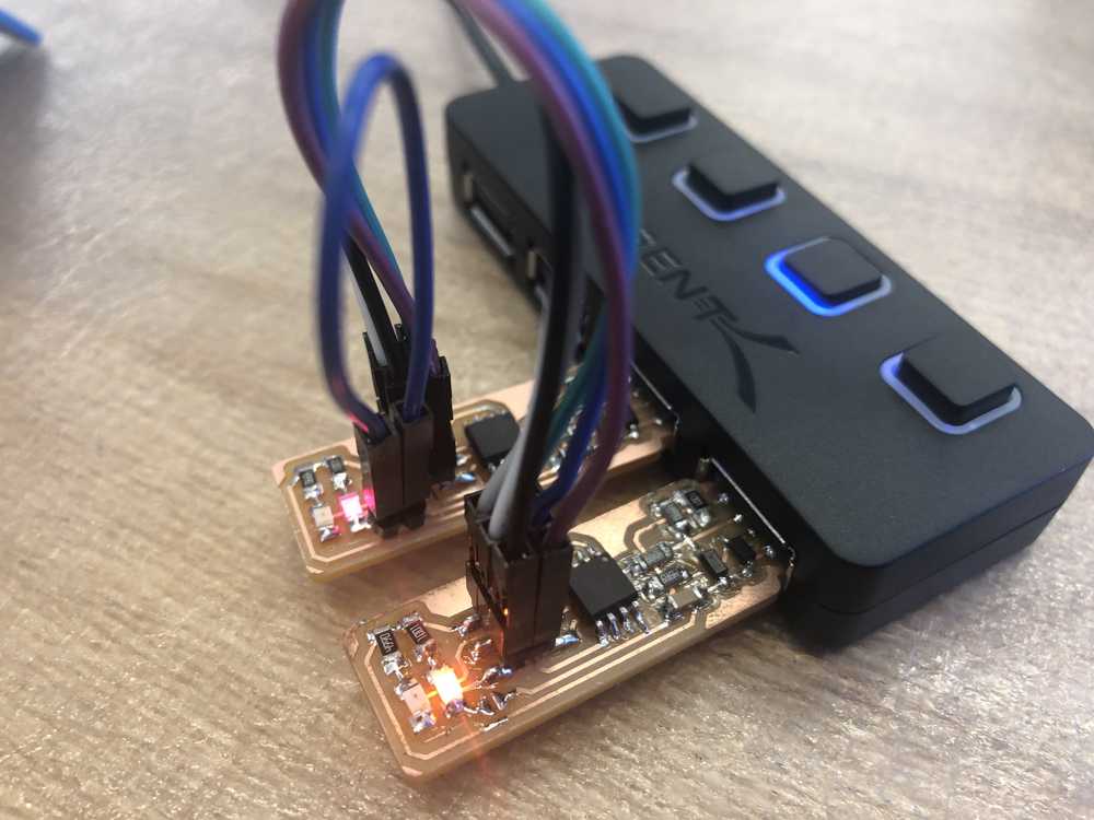
Adding the Components
The first thing I learned while trying to solder the tiny board is that it is much easier to solder once the board was stuck to the soldering surface with double sided tape. After soldering half of the board with moderate success, I discovered the existence of both a a soldering iron with a finer tip and thinner solder. This helped my soldering be more precise and localized to the actual components.

On first inspection, the board looks good. As a quick check, I did a continuity test to check for any shorts between Vcc and Gnd. The board passed. For now, it seems safe to proceed to programming the ATtiny45.
Programming the ATtiny45
I was not able to get my computer to interface with either the programmer or my programee.

Characterizing the Mill
For future reference, when I begin to design my own PCB boards, it will be helpful to have characterized the mill abilities. In particular, I will want to know how thin and close together traces can be. I milled out the following traces (file provided by Neil):
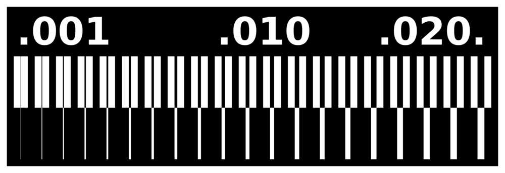
Here is the result:

The board has a lot of burrs around the edges so I used some light sandpaper to remove them:

One thing to note is that just because the very thin trace all the way on the left appears, across a longer distance and away from where the height of the end-mill was calibrated, the trace might break. Thus as a design rule, I will plan to use traces no thinner than 0.006 mm.