Week 9
~ output devices ~
This week on HTMAA, Hannah learns to output data from an ATMEGA to an LCD screen and vibration motor.
Highlights include finding Eagle libraries for parts not in the standard FAB library, making custom libraries based off of datasheets, and making (designing and milling) double sided boards.
Struggles include figuring out that the ATMega16U2 datasheet is… inconsistent!? Gasp!
Creating the PCB
Several of the parts I am using are not in the FAB library of parts. After a bit of searching I found SnapEDA that seems to have a fairly good workflow with Eagle. Basically you download the part, open it has a library in Eagle, and make sure to mark said library as “active.”
This tutorial on creating eagle packages was extremely helpful. I ended up using this resource to make custom header pins and also to edit the pin connection diagram for the ADXL343.
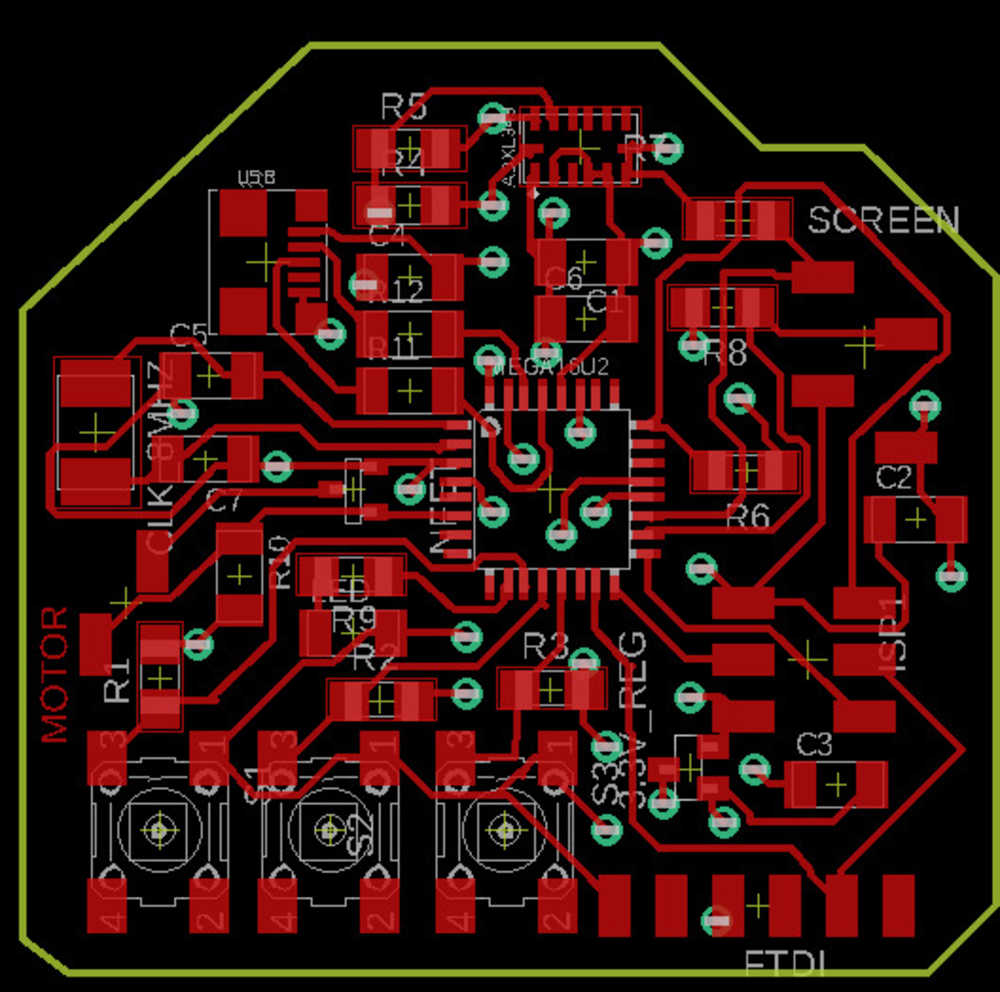
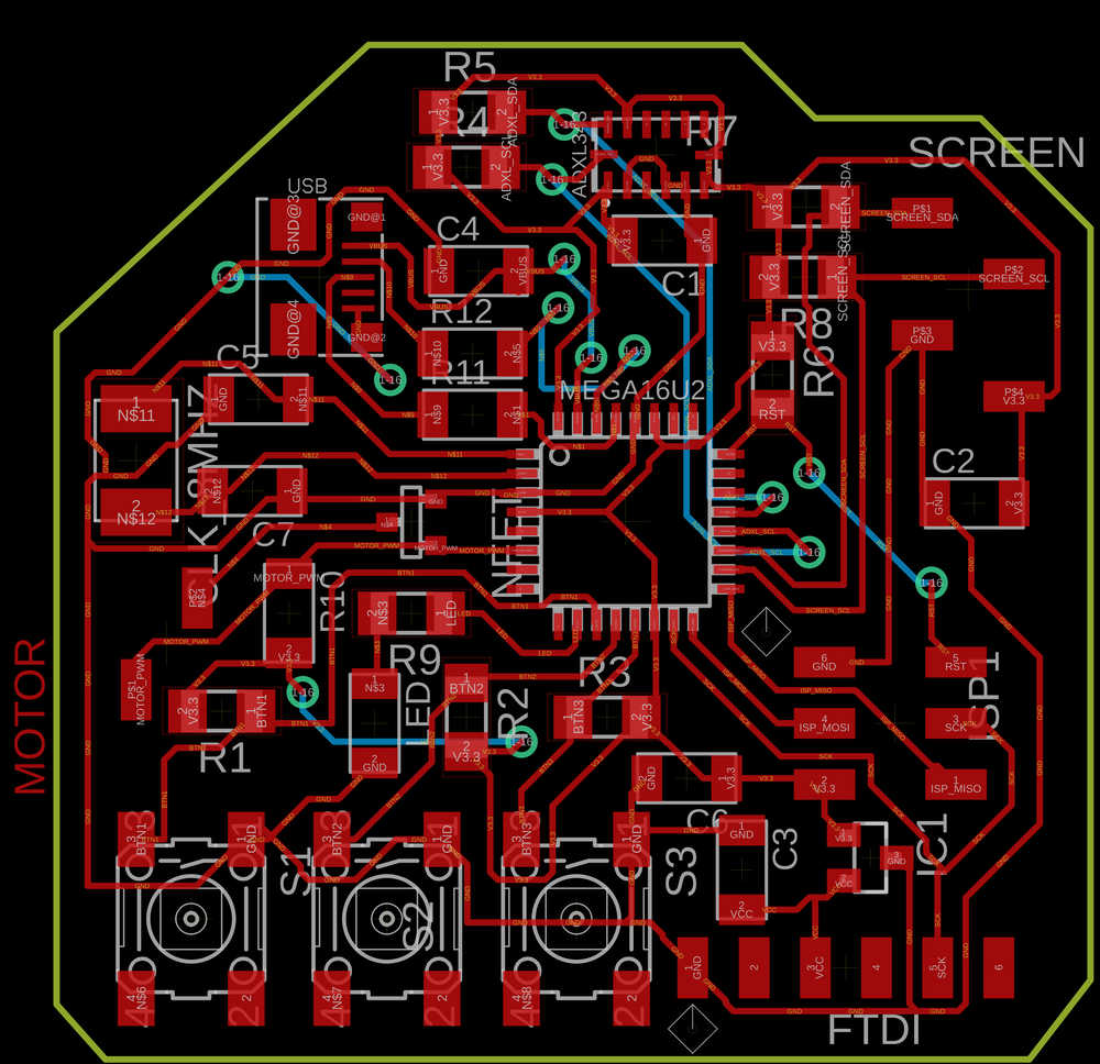
This board took FOREVER to design. My goal was to have the accelerometer, motor, screen, three buttons, and a debugging LED–everything I needed for my final project board. The main thing I learned was that I should wait until after I start placing all the components to choose pins for the peripherals. That is, the ISP pins must go to specific pins on the microprocessor, but everything else is for the most part up for grabs. Doing this later will prevent me from having unnecessary wire crossings to deal with.
USB Details
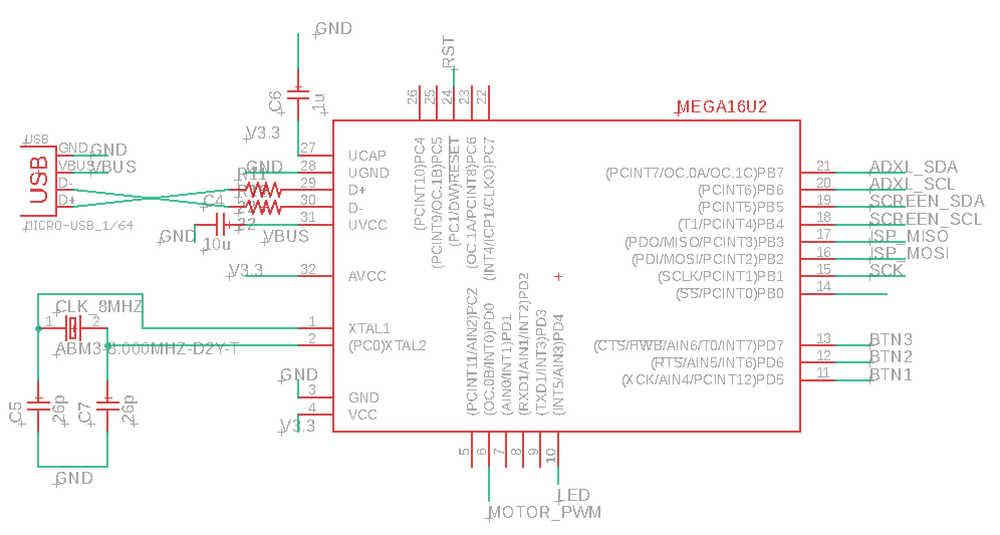
Finally, I was very eager to try programming the board directly over USB, which was partly why I chose the ATMega16U2 chip in the first place. Figuring out how to connect that was non-trivial. The 16U2 datasheet essentially lists crucial design guidelines (see section 20 titled “USB Controller”):

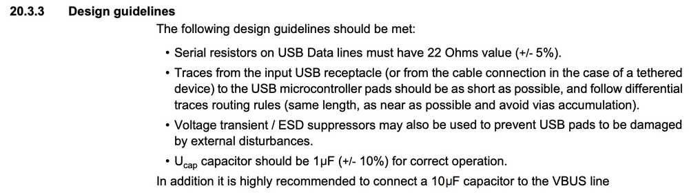
Furthermore, since I am using a 3.3 V regulator on the board to power the accelerometer, I selected “typical self powered application with 3.0 - 3.6 V I/O” which had a particular method of setup:

One thing to note is that this design (as well as all other USB designs) requires an oscillator (see the device hooked up to XTAL1 and XTAL2).
The datasheet gives information about the speed of the external oscillator:
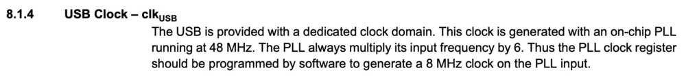
Following guideline 8.1.4, I chose an 8 MHz clock so I wouldn’t have to worry about the clock multipliers not being correct at startup or anything like that. Since the listed tolerance for the 48 MHz clock is 0.25%, and resonators have 0.5% tolerance (ceramic resonators are less accurate than quartz crystals), so I selected the 8 MHz crystal oscillator for the system’s clock.
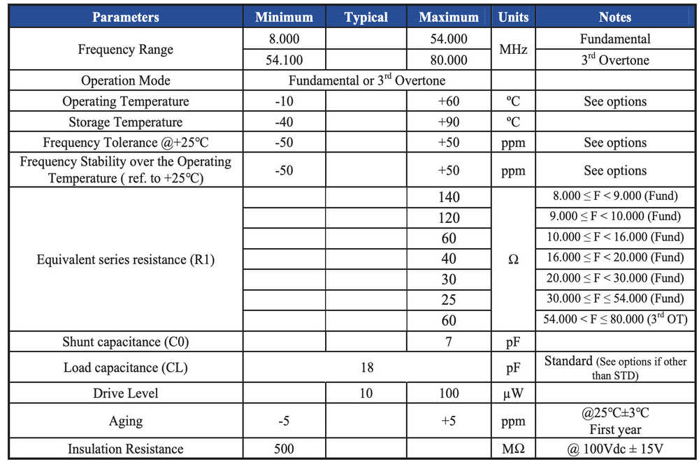
The last thing to choose about the oscillator is the capacitors. I found a helpful article. Basically you have to account for the “load capacitance” (listed in the crystal’s datasheet) and “stray capacitance” (something you have to guestimate).
Then the formula is
CL = C1*C2/(C1+C2) + Cstray
Coming from circuit land, this formula looks like saying the total capacitance (i.e. load capacitance) has to be equal to the series value of C1 and C2 along with the parallel value of the stray capacitance. Interesting stuff–definitely plan to read up more on it when this week is done.
The crystal in lab is the ABM3-8MHz-D2Y-T and the package also lists it as an “18 pF SMD”… this was a hint that CL is 18 pF, but I checked the data sheet just to be safe. Surely enough:
The final board design looks like this:
Double Sided Boards On OtherMill
Steps
Clear the OtherMill surface, leaving only the bracket
Insert a tool upside down and begin locate bracket mode (see video below)
To mill the top of the board, select only traces and holes (not the outline–otherwise flipping over the board will ruin alignment) and chose “mill top of board.” Align the double sided board with tape aligned along bottom left
When top milling is complete, remove the board, tape the other side, and align with the bottom right of the bracket. This time select “mill bottom of board.”
- Tip: use .9 mm via’s in Eagle design. Then the 1⁄32 inch bit = 0.8 mm has some clearance to mill out a hole. Ultimately the rivet used will bee .6 mm.
- Tip: mill holes on both sides to ensure they go through, but only mill outline on one side.
- Tip: Use 1⁄64 Flat End mill and 1⁄32 PCB Conservative (be careful–using the default 1⁄32 Flat End mill will ruin your traces as it is way too fast).
Video of the OtherMill locating the bracket:
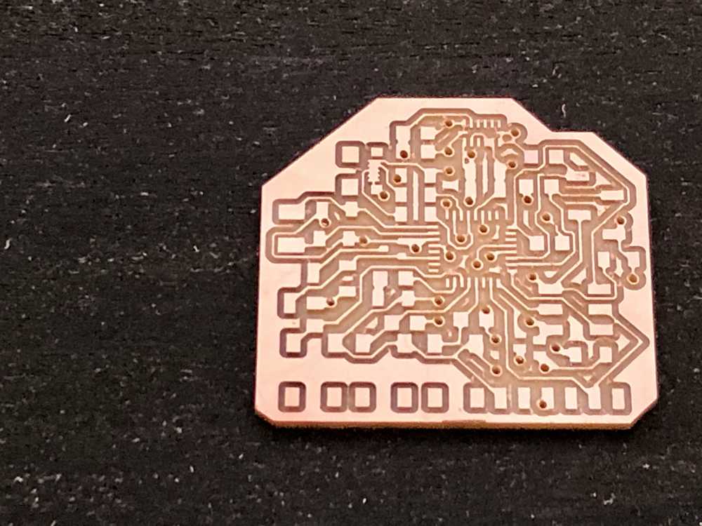
The board fresh of the mill:
And with the .6 mm rivets inserted:
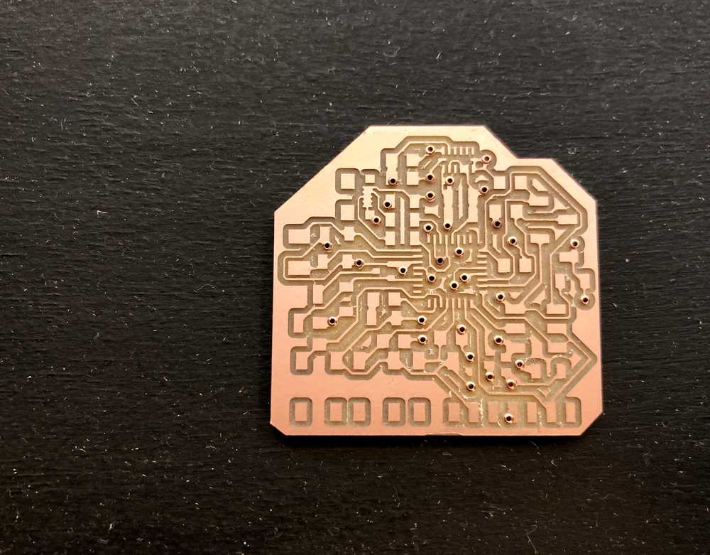
- Tip: when inserting rivets, first load the rivet into the hole, then slide the PCB with the rivet into the bit on the rivet-presser (not sure what the official name of that piece of equipment is), and then slowly press down. Most importantly, hold the board down while slowly lifting up the bit. I found that helpful because otherwise when trying to dislodge the PCB from the bit the machine would steal the rivet from my PCB
The last step related to double sided boards is to solder the rivets to the board. Not only do you need to make sure the rivet is soldered, but that solder must connect to the neighboring traces. It seems like it wouldn’t matter, but later on I found opens where I had failed to do that.
Fuse Bits
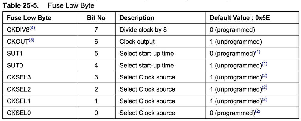


- CKDIV8 = 0 for programmed | divide by 8 at startup
- CKOUT = 0 for programmed
- SUT1:0 = 11 slowly rising power
- CKSEL3:0 = 0111 for full swing crystal oscillator
- CKSEL0 = 1 for crystal oscillator, slowly rising power
Low Fuse Bits = 0’b00110111 = 0x37
IT WON’T PROGRAM :(
After hours of probing pins and talking with TA’s (Ben called it the “ghost board”), I finally decided I would just try to remake it and maybe that would solve the problem. (Spoiler alert: it doesn’t).
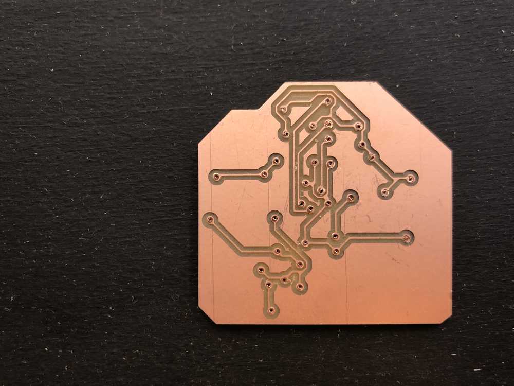
The new board was significantly better designed–it had way fewer through hole traces. It’s crazy how much practice can improve your design even when you think it was already as good as it gets! I haven’t quite hit Malcolm Gladwell’s 10 thousand hour rule for routing traces yet, but I’m sure I will soon.

And… the new board doesn’t program.
This was, to be quite honest, the first time in this class I’ve felt truly disheartened in this class. Basically, for a few days, I couldn’t make any progress. I kept trying different things, researching different things… nothing.
Finally I realized what was going on. There is a discrepancy in the datasheet!
In the following section they state that the defualt clock is the 8 MHz internal oscillator:
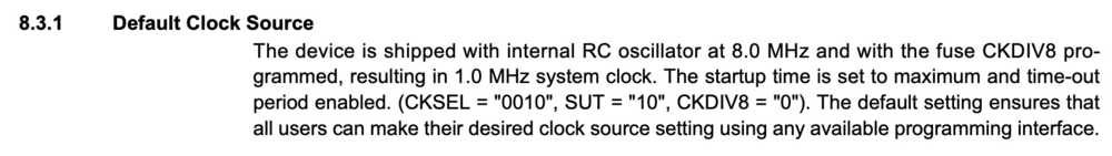
But in the fuse bits section (which I include again below, the default is cksel[3:0] = 1110, which corresponds to using an external low power crystal oscillator!
And I’m not the only one to have found this error. A post on an internet forum from a confused and frustrated hobbyist confirmed my troubles.
Now for the real “kicker”: at the tine of stuffing the board, I could not find the package of 8 MHz crystal oscillators. I naively imagined that it wouldn’t be a problem at all to just solder that in later–in fact I thought it would be easier to first get the basics of the circuit working and then worry about setting the fuse bits and all of that. Dios mio! So basically, the fuse bits actually are programmed (apparently accidentally?) to rely on an external oscillator… which I hadn’t connected.
As soon as I had this realization I ran to the backroom and started frantically sifting through all the components, desperately looking for the bag of 8 MHz crystal oscillators (although I now realize really anything external would have probably worked simply to get the board programmed–the 8 MHz crystal is only for the USB support). I found it, soldered it on, ran back to my computer, uploaded the program and … BAM! It worked!
Setting Pins
- BTN1 = PD5 (leftmost)
- BTN2 = PD6 (middle)
- BTN3 = PD7 (rightmost)
- LED = PD4 | output
- MOTOR = PD0 | output
- ADXL_SDA = PB7
- ADXL_SCL = PB6
- SCREEN_SDA = PB5
- SCREEN_SCL = PB4
- FTDI Serial Out = PB1 | output
Although in Week 06 (Embedded Programming), I wrote the code without macros to make sure I really understood what was going on, from now on I plan to use the macros for ease of use.
#define led PD4
#define led_port PORTD
#define led_pin (1 << led)
#define led_direction DDRD
#define btn_port PORTD
#define btn_pins PIND
#define btnl PD5 //button left
#define btnl_pin (1<< btnl)
#define btnm PD6 //button middle
#define btnm_pin (1<<btnm)
#define btnr PD7 //button right
#define btnr_pin (1<<btnr)
#define motor PD0
#define motor_pin (1<<motor)
#define motor_direction DDRD
#define motor_port PORTD
Since the led and motor are controlled by output of the microcontroller pins, we need to set those pins as output; pins are inputs by default.
output(led_direction, led_pin); //set LED as output
Output(motor_direction, motor_pin); //set motor as output
Motor
And now to control the motor by pressing the left button:
  //motor
  if (pin_test(btn_pins,btnl_pin) == btnl_pin){
     clear(motor_port, motor_pin);
  } else
  {
     set(motor_port, motor_pin);
  }
Easy! Motor working. It is pretty intense even with the 490 ohm resistor, so I’ll plan to get the PWM nature of its pin (OC0A) set up.
OLED Screen
Using Neil’s Oled code, this was pretty easy. I only ran into two issues.
The first was a soldering issue. After uploading Neil’s code with the appropriate SDA and SCL pins entered, the screen did not turn on. My first intuition was to check that the device was receiving power. In fact, it wasn’t! For some reason, a trace next to the screen connected to V3.3 was discontinuous around a corner. I added some solder and this fixed the problem.
The next issue was with finding the right I2C address.
The back of the OLED has the ability to solder a 0 ohm resistor to two places. Presumably, soldering it one place pulls the pin low and the other high allowing for selection of one of the two addresses printed on the device (0x7A and 0x78). Neither of these two worked. I pulled out the MSOX3054A scope again and opened up its I2C mode. It showed that the I2C communication was essentially working, but the only data being sent was a ping for the address and a lack of response. Premila happened to be in the room so I asked her about this. Turns out the address to make it work is neither of the listed ones. It is 0x7C.
After changing this, the screen works!

Combining Accelerometer and OLED Code
So the next step is to put the code from my input device (accelerometer) and output devices (OLED display and motor) into one file.
The problem is that I had not looked carefully into the OLED and accelerometer I2C bit-banging code beforehand and so assumed they should each have separate SDA/SCL pins from each-other. The strength of the standard I2C protocol is that it allows multiple devices to all talk to each other only using two data-lines (SDA and SCL).
When I went to combine the code, I quickly realized I had two options:
1) duplicate all of Neil’s I2C functions with one set for the screen and one set for the accelerometer 2) short together the SDA and SCL pins for the two devices on the PCB.
I decided to go with the second, as duplicating an entire set of code would make the code file unnecessarily unwieldy and seemed more prone to error.
I managed to add a small piece of wire to short the SDA lines and added a 0 ohm resistor to short the SCL lines. Since I would only be using one set of the pins to talk with the devices I needed to set the other pins (to which they are shorted) as inputs with pullup resistors. This way their beheavior won’t accidentally try to cross the driven behavior of the pins to which they are shorted. I added the following two lines of code:
//initialize unused SDA/SCL as input pullup
set(SDA_port, SDA_pin_unused); //make input pullup
set(SCL_port, SCL_pin_unused); //make input pullup
Input and Output Board Ready to Go … almost
Just as I was documenting the motor behavior, it fell out of my hands, ripping up its traces as it went… oh no!
First I tried to flatten out the traces and crazy glue it back together. Continuity test said this was ok, but when I tried to start the motor, there was no response. So I pulled out the components again and this time sketchily soldered some veryyyy thin magnet wire directly from the fet and power pins to the motor. Continuity test said it was good! Again, no response. In disbelief, I tried connecting the motor directly to a power supply… no response! So probably this whole time the circuit had in fact remained intact, and it was the motor itself that was broken.
Harrison kindly lent me one of the vibration motors he his using for his project. Hooked it up, and the circuit vibrated once more.
Now it’s all systems go! The rest of the work on this board continues on my final project tracking page.