Week 3
~ printing and scanning ~
This week on HTMAA, Hannah learns to use a 3D printer to make a snap-fit box with a hinge. It can only be made using additive manufacturing.
3D Printing
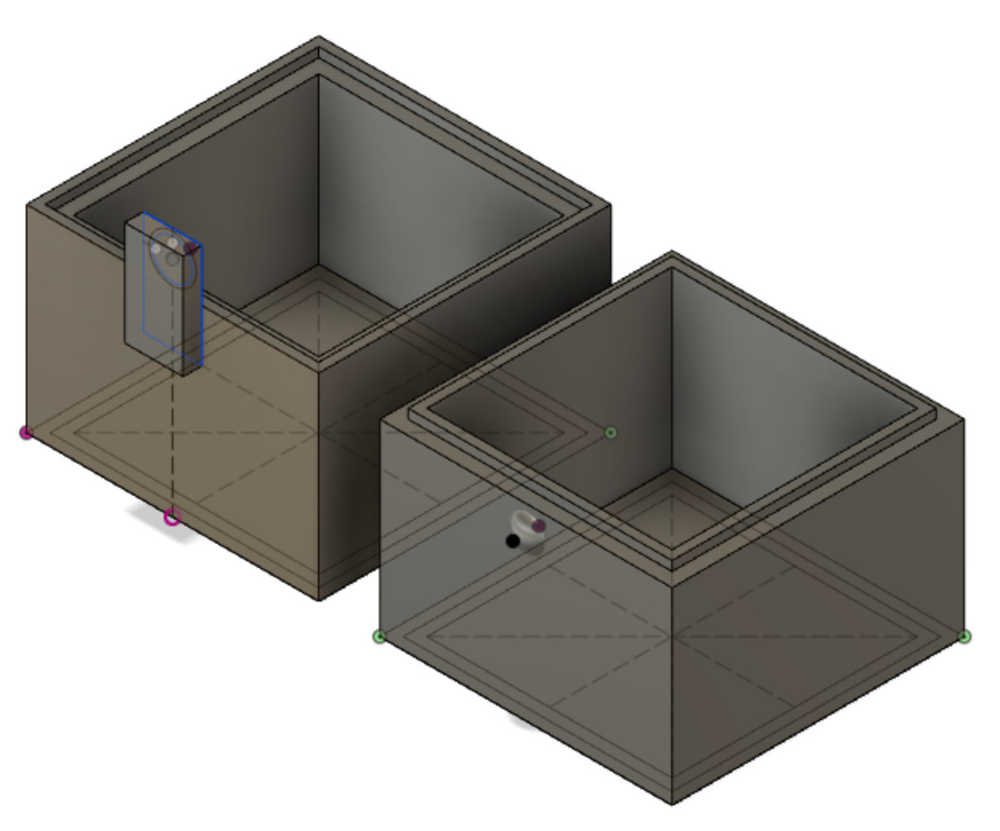
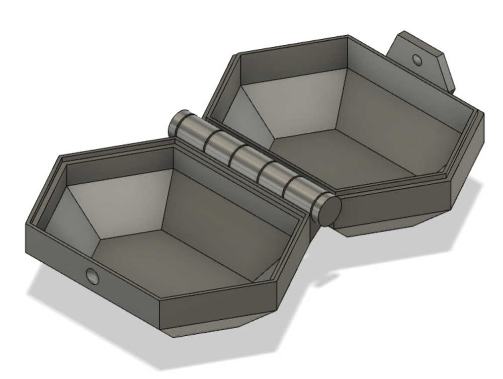
For this week’s project, I decided to make a box: (1) I wanted to learn how to do a joint and (2) I wanted something to hold the programmer I made last week.
I finished up the CAD and brought it in to EDS to print. After discussion with the TAs, it looks like I should make some very small (thus fast) test pieces to check the injection molding snap-fit tolerance. Basically, I need to be aware of (similar to kerf on the laser) whether or not the insert and hole have more and less material than parametrized, and account for that in the CAD drawing.
My smaller test boxes are approximately half an inch tall and an inch wide. I printed one set of boxes with 0.8 mm of overhang and one with 0.4 mm of overhang. I chose these numbers because the diameter of the PLA filament is 0.4 mm in diameter, so these overhang values represent two and one layers of overhang respectively.
Here they are:

And in the 3D software on the printer:
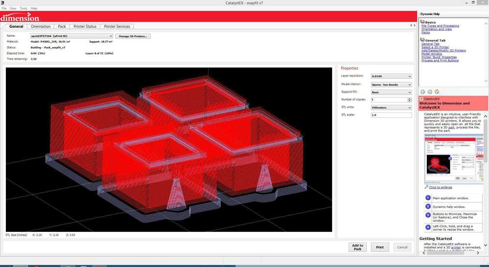
The special thing about the Stratasys uPrint 3D printer is that it has a separate filament for the printing and support material. This allows printing of more complicated, non-planar geometries since the support material dissolves in the bath. So what we are seeing in the image of the 3D printing software is the boundaries of the actual structure in red and the boundaries of support material in white.
Let’s go!
These two test pieces took about 2.5 hours to print. Here is the result:
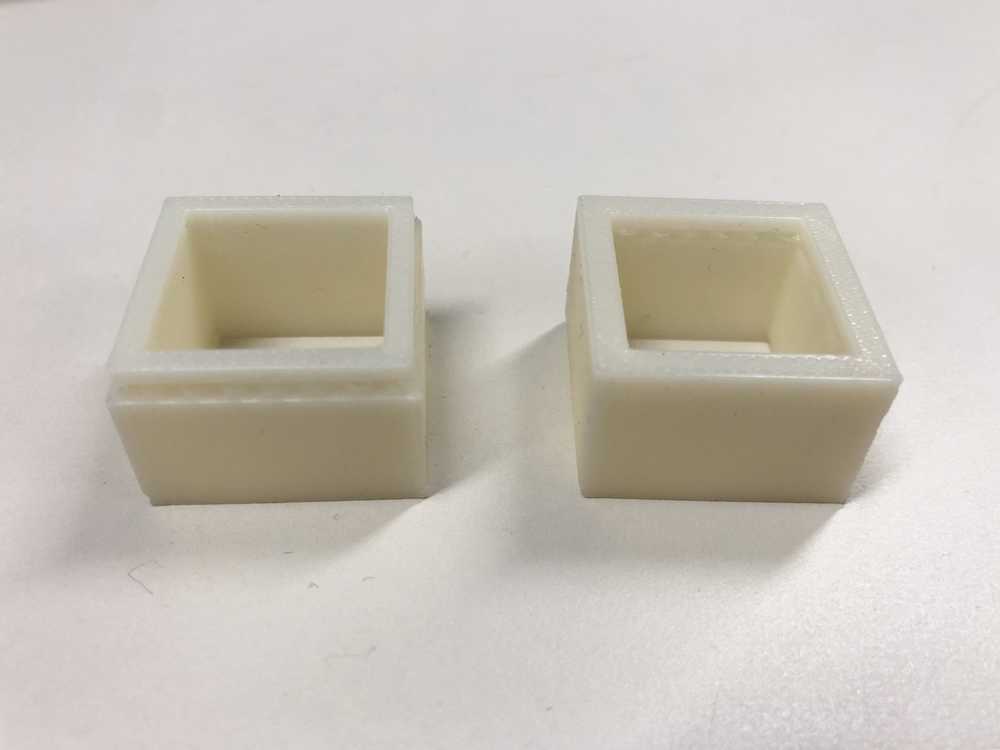
Well, I feel incredibly silly. Basically, I didn’t have a good enough conception of the actual scale on which I was working, so my intuition that the rim would deform when pressed into place was just totally absurd. In fact, this was a lot of material and it is very rigid.
Back to the drawing board. https://markforged.com/blog/joinery-onyx/. This time I will try simply having a lip that acts as a sealant and not as a snap joint. The closure mechanism this time will be a small “bump” on the side of the bottom box in combination with a small indent on a clasp on the top box.
Off to the printers!

Whoops, didn’t account for a clearance gap, so the halves don’t fit together. I took some measurements anyways:
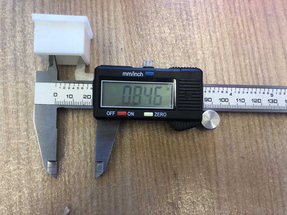
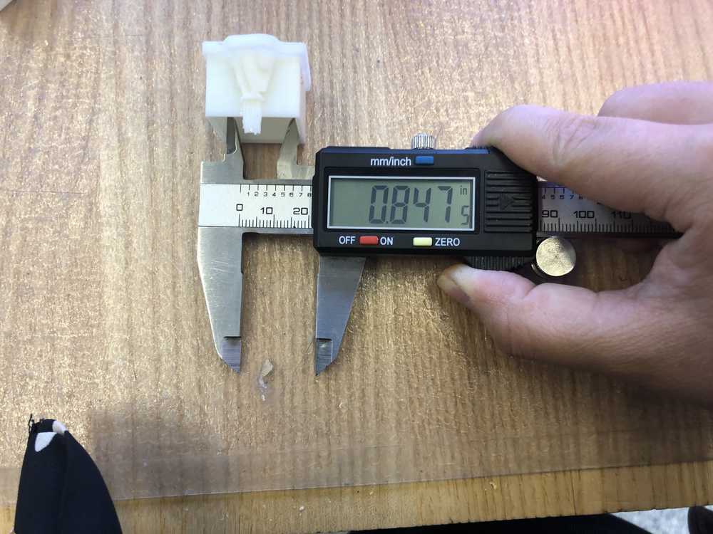
Let’s take a look at the clearance test piece:
![]()
So what this means is the piece that has a total diameter gap of 0.6 mm succeeds. Specifically, this implies that the radial gap of 0.3 mm is the joint clearance. I will use 0.4 mm just to be safe. This makes sense, since 0.4 mm is precisely the nozzle diameter.
One question I have is the following: given that the filament diameter is 0.4 mm and the lip of the box is 2 diameters wide, if I want to have clearance can I make both sides 1.5 mm or do the units have to be multiples of the diameter for it to work. One thing I am really realizing while iterating through this process is that, because the object I am trying to make is so small, many of the important features (e.g., the clasp, the lip) are limited by the filament diameter. Basically, in order to get everything to fit together I really need to be making sketch dimensions in terms of multiples of the 0,4 mm filament diameter. When I have more time, I would like to explore how necessary this is: both the accuracy of the motor controlling the filament location and the diameter of the filament itself affect the dimensions I need to use, and each of these aspects affects different design elements.
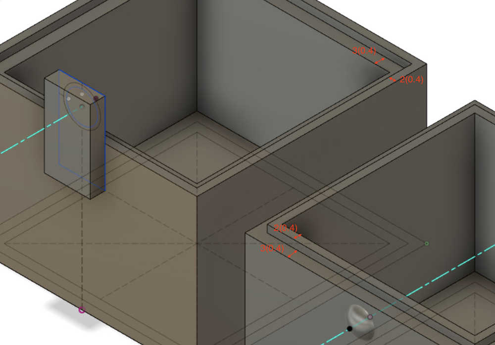
Anyways, accounting for the clearance gap, the lip dimensions now look like the following:
Ok here we go…
It works! Woohooo! The pieces make a very satisfying audible snap when pressing them together. Perfection.
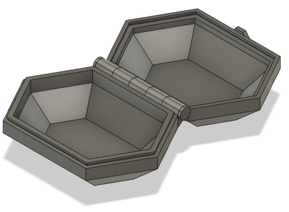
Using what I’ve learned with these test pieces, I edited my original box design. As I added the bump and its corresponding depression it occurred to me that I could further improve the design by placing the depression on the box rather than on the tab because the tab is more susceptible to material deformation while it is printing. We’ll see if this intuition checks out. Furthermore, to save printing time (the original estimated job was around 7 hours), I made the whole thing quite a bit smaller.
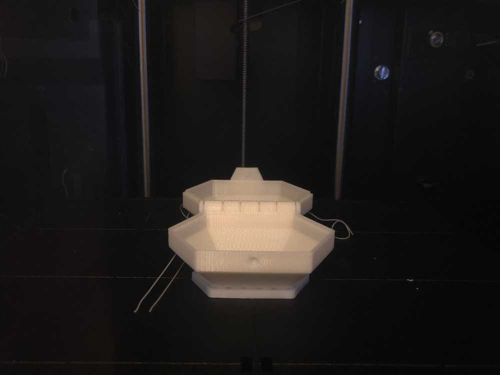
Sent to the printer. 2.5 hour print job and then probably a solid hour in the bath to dissolve the support material that is definitely going to be very stuck around the axle. Now we wait.
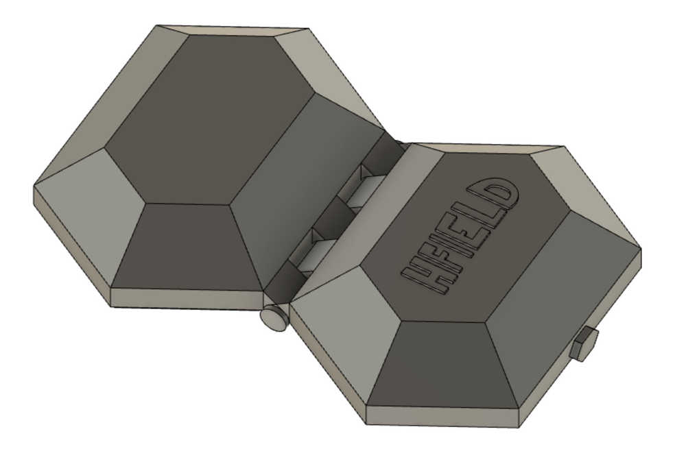
Just out of the printer:

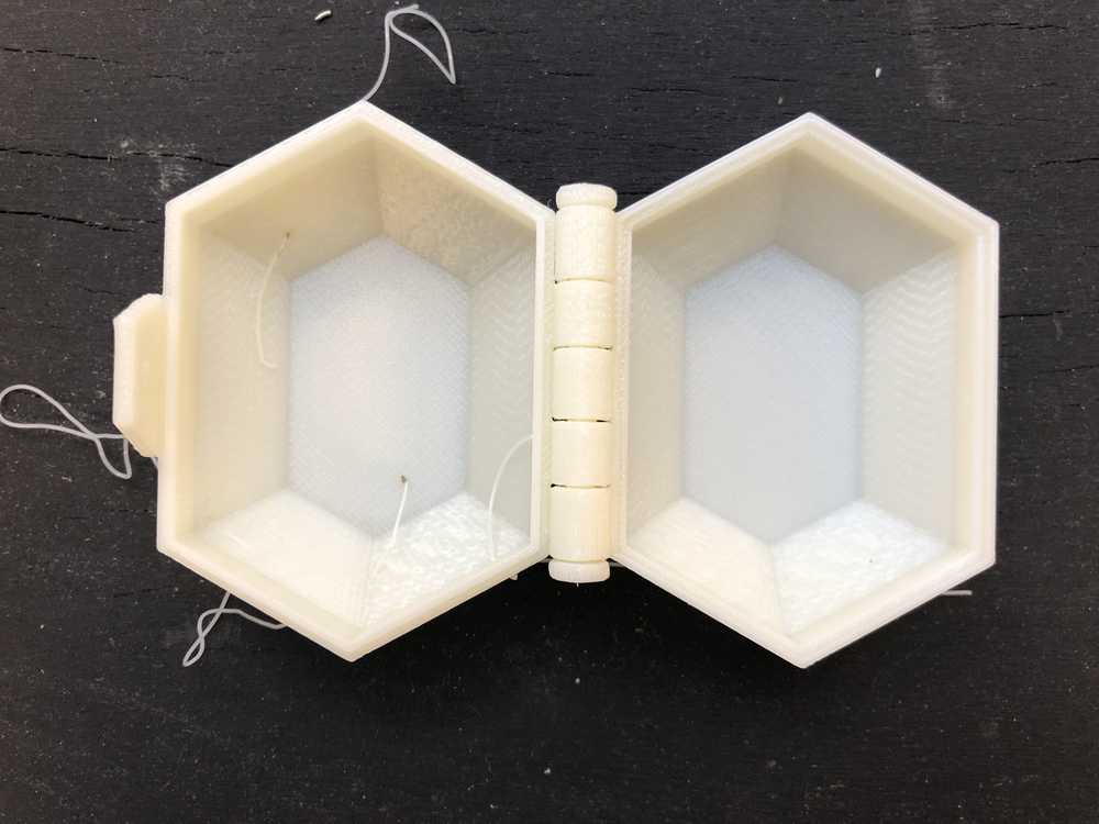
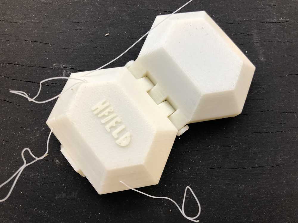
And… it’s out of the bath! The axle required a little bit of sanding in order to open smoothly. Overall, I’m really happy with how this turned out. The snap shut sound is very satisfying. I have had several friends request their own customized version of it.
3D Scanning
A few years ago, a group of MIT students realized that since there is no encryption on the MIT RFID card readers, they could read off the phase encoded personal bits that make up your MIT ID card and add those to the memory on any another RFID chip. Then, they 3D printed brass rats and inserted the chips inside, thus allowing you to scan into buildings by “fist-bumping” the RFID reader. Ever since I heard about that project, I’ve wanted to do this myself. So for this week, as a first step, I would like to make a 3D model of my brass rat.
The EDS shop scanner only detects very low resolution features and only works on large, non-reflective surfaces. So I decided to go explore the more expensive scanners in the CBA shop.