Week 4
~ PCB designing ~
This week on HTMAA, Hannah learns to design her own circuit board using Eagle.
Designing with Eagle
Starting off I had some trouble. I was trying to add the fab library to Eagle, but I was working with some sort of corrupted file. Eventually I realized this, and deleted and re-downlaoded it. Along with clicking around and the help of some past Fab Academy documentation here and here, I eventually figured out how to add components.
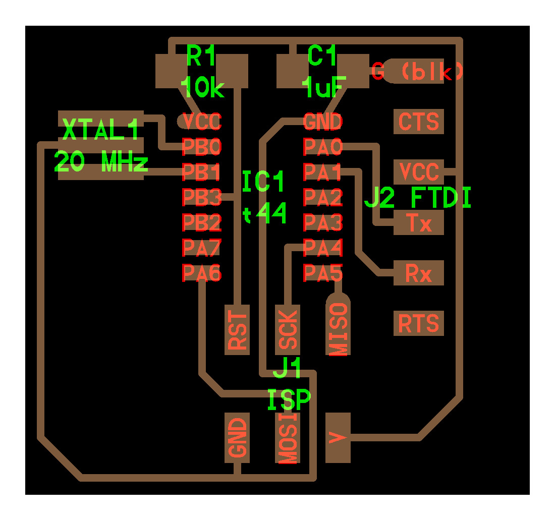
The basic design we want to create is the following:
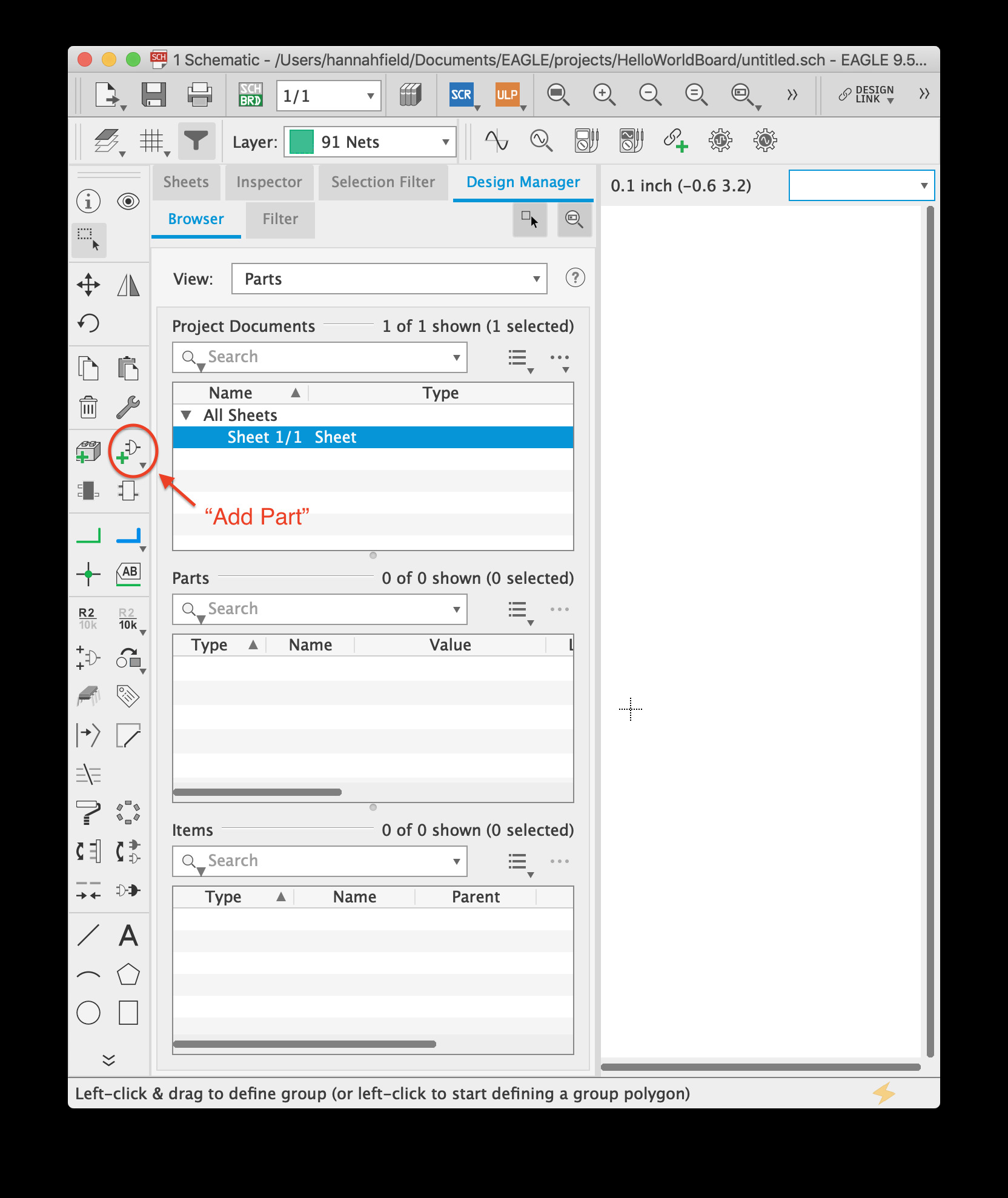
Step 1: Add the fab library (.lbr) file to the library folder inside the EAGLE folder.
Right click on the library, and mark as used. Without this step, you will not be able to access the parts.

Step 2: Create a project, create a schematic within the project, and click the add part button, which will open up a navigation system containing all parts in the used libraries.
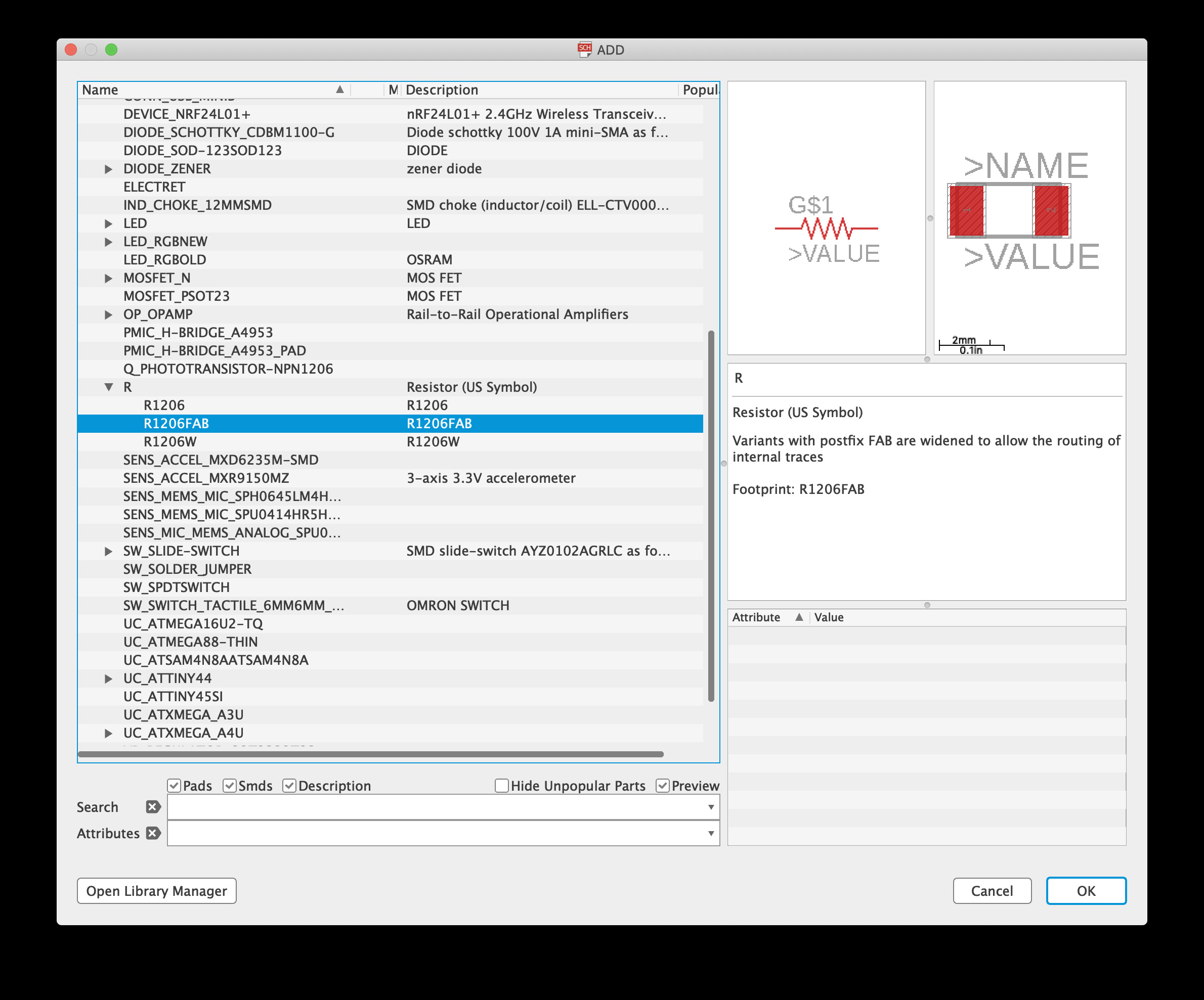
Step 3: Add components. It is a little bit confusing which version of the part you actually want.
Adding a Switch and LED
For this, it was helpful to consult the ATTiny44 datasheet. From the datasheet we see that the processor can run on 3V or 5V. We are powering it through USB, which is 5V, so Vcc = 5 V. The data sheet states that total current should be less than 60 mA and individual currents from pins should be less than 10 mA. This means that if we ever have a pin connecting 5V to ground we should use a resistor of size at least 10 mA > I = 5V/R or in other words R > 5V/10mA = 500 ohms. We will use 10 kOhm resistors to be on the super safe side, which would correspond to pin currents of I = 5V/10kOhm = 0.5 mA. The only electrical downside of larger resistors is that if coupled with any extra capacitances in the circuit, there could be extra RC time delays. We don’t have to worry about that for the simple design of this circuit.
Now we move onto sizing the resistor for the LED.
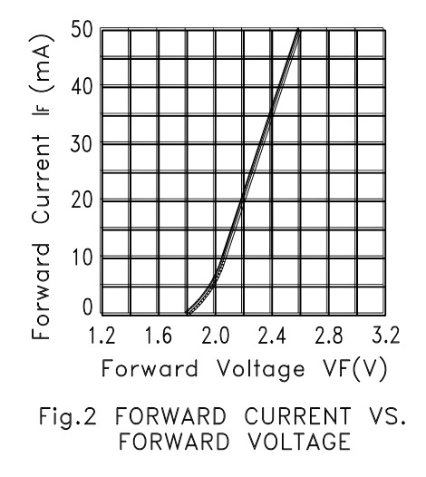
The graph above shows the iv curve for the green fablab LED (LTST-C150GKT). We see that it has a minimum forward voltage of 1.8 V in order to allow current through. Thus in order for current sourced from the ATTiny pin to be under the 10 mA limit we must have a current limiting resistor in series with the LED of at least R > (5 V - 1.8 V)/(10 mA) = 320. Thus we will use the closest existing lab resistor which is 499 ohms. Note that we prefer larger current going through the LED since that will make it brighter.
With all the components placed it looks like this:
Step 4: Now we need to connect up components. We can do this with the “Net” tool. Conveniently, by naming ends of nets, we can make different ports associated via a wire without explicitly drawing the wire. Note: make sure to use “Name” and not “Label.” Label will simply display what the part has been named but not allow you to name it.
With all that done, we have the following:

Onto board placement!
Step 5: We click the “switch between board/schematic view button.” What a mess:

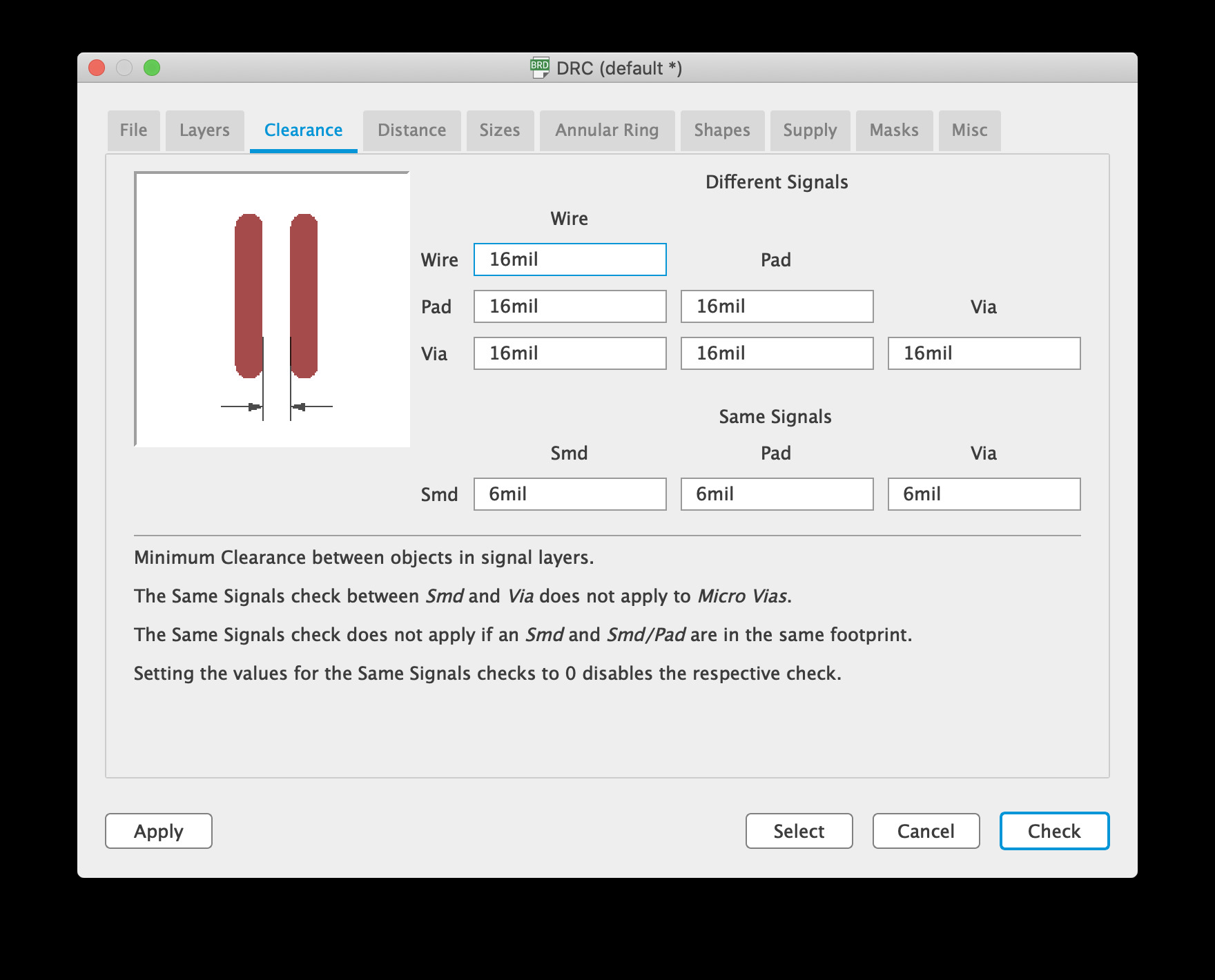
First we need to check that the design rules file specifies that the traces must be at least 16 mils apart, a value we found experimentally for our mill in Week 2.

Now onto the artful task of arranging components on the board. I was having a lot of trouble for a while–I couldn’t seem to move components. After a lot of google I found that I needed to set the “layer” I was working on to “on” so that the crosses appear in the middle of components, allowing me to move them around.

And… well routing is no easy task. I ultimately had to use a zero ohm resistor to complete all the connections.

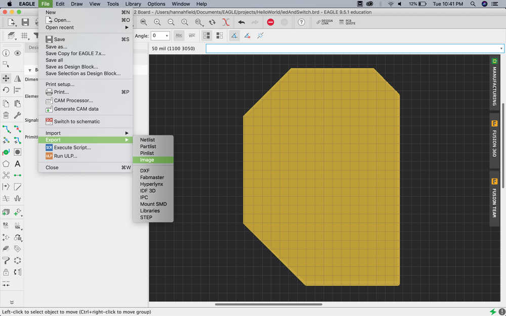
Step 6: Using the polygon feature in Eagle, I was able to customize a shape for the board trace.
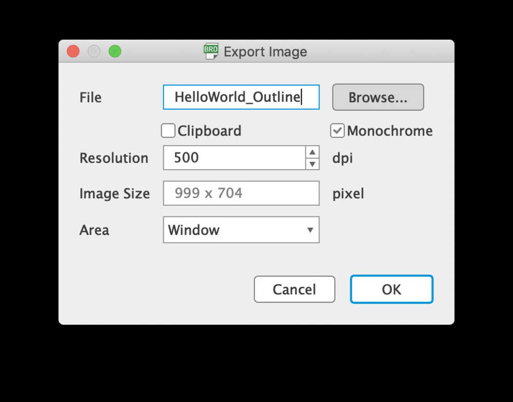
500 is a good value to use for DPI. I also found it necessary to set the area to “window” so that the image was appropriately sized. Finally, select monochrome, so that the image will be black and white, which is what the mod’s server reads.
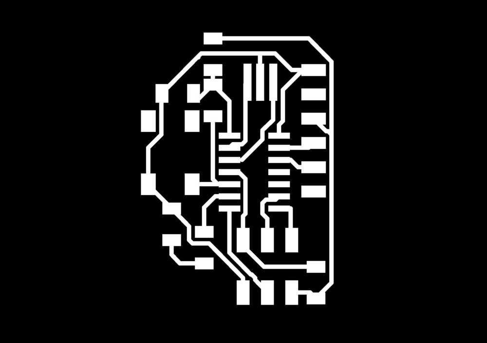
And these are the two files I generated (one has traces and the other has the board cut-out):

One thing to note about the Roland SRM-20 is that, due to either a bug in Eagle or in mods (or a fact of converting from DPI to PPI), but if the file exported in Eagle was 500 DPI, then in mods, the dpi should be twice that, so 1000 DPI.
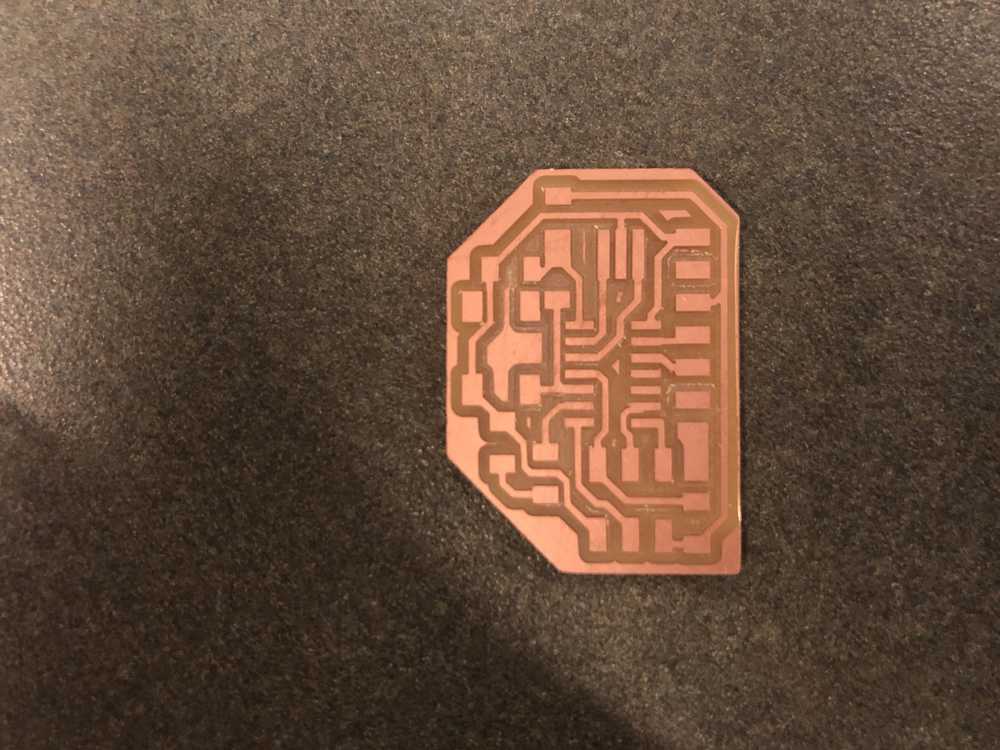
Much to my dismay, after I soldered on a couple components I got the sense that I had shorted resister R3 to ground… but even worse than shorting it myself was learning that the board itself contained large number of shorts. Essentially, Eagle was ignoring the 16 mil spacing so some traces I had drawn were less than that.
Using the OtherMill
So, other students were using the Roland, so I decided to give the OtherMill a go. Because the Bantam software can print directly from .brd files, the process for printing was much easier. Furthermore, the OtherMill figures out itself the optimal combination of end mill sizes to use for the board so the overall cutting time is greatly reduced.

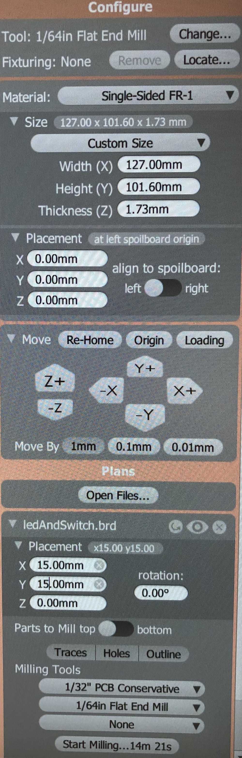
The system prompts you when it is time to switch end mills:

Unfortunately, due to some sort of rotor issue, the surface finish produced by the OtherMill was quite terrible. On the other hand, there were no accidental shorts. Despite my best sanding efforts, I was not able to clean up the surface very much:

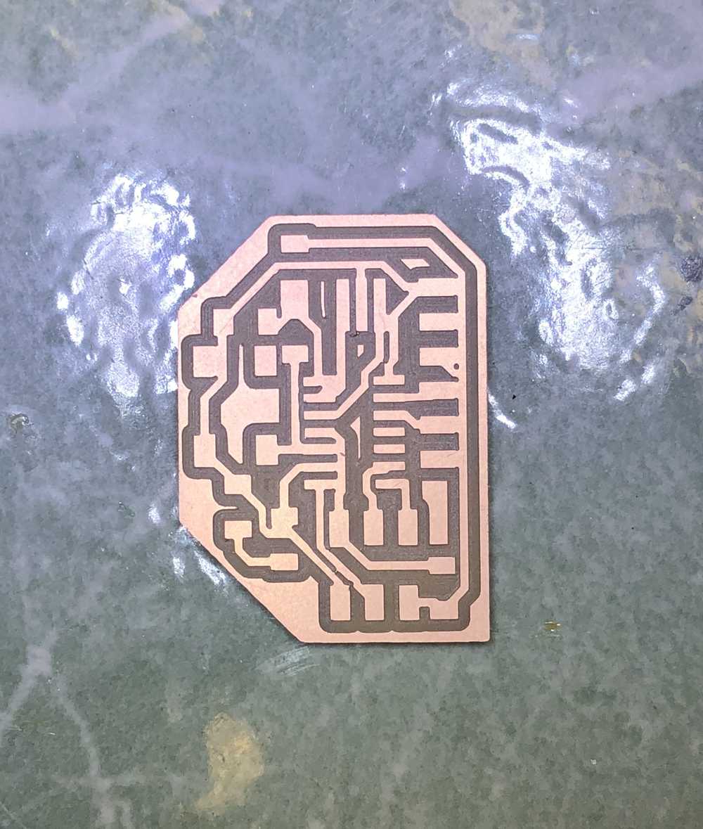
I ended up redo-ing the mill on the Roland because I was so bothered by the look of the (functional) board. On the bright side, with the number of times I had to do this milling, I have become comfortable with the process of operating the mills and their respective software, which will serve me well in the future.
Stuffing the Board
The technique of taping the board to the table + adding a dot of solder to the board before adding the component makes the soldering process quite seamless! This is the finished result:

Programming the Board
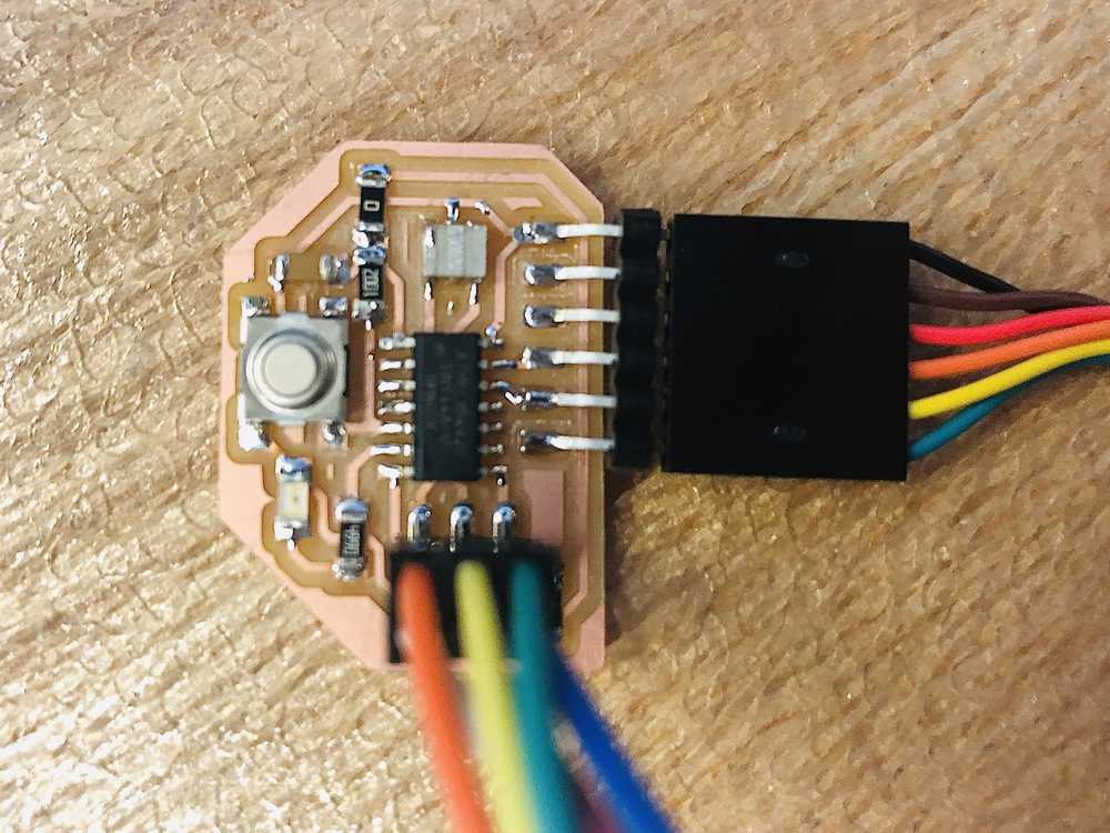
Ready to program! We use the programmer we made in Week 2 to load the program onto the new board. Basically, the programmer connects via USB to the computer, and during programming, the new PCB is connected via FTDI-USB to the computer (for power receiving purposes). The programmer and new PCB are connected via the 6-pin header, and this is how the program is transferred.

1) Make a folder with the .c file and the .make file. In this case the files are echo.c and echo.c.make
2) Run
make -f hello.ftdi.44.echo.make
3) Run
make -f hello.ftdi.44.echo.make program-usbtiny
4) Run
make -f hello.ftdi.44.echo.make program-usbtiny-fuses
Testing the Board
So, the board has an LED and button, but the code provided by Neil is for the basic board without these features. Thankfully, I don’t have to wait impatiently until week 6 when we learn how to program our board. Neil’s code still tests basic functionality of the board by interfacing through the FTDI port to “echo” characters sent to the ATTiny. And… it works! I was even able to do this on my Mac with a USB-C adapter.
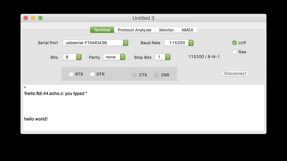
I believe this worked since the fuses were blown on the ATTiny so that it would rely on the external 20 MHz oscillator for it’s timing. Basically, the board is able to now operate with the stricter USB-C timing constraints. I also have a hunch that I may be able to reprogram the device now that it relies on the external oscillator. We’ll see in two weeks!