Week 12: Interface and Application Programming
Assignments
This week’s assignment was to write an application that interfaces a user with an input &/or output device that I made. Because I was working on my final project at the same time, I followed this tutorial on randomnerdtutorials for this week’s assignment, where I learned how to build a web server to power 2 LEDs.
Breadboard
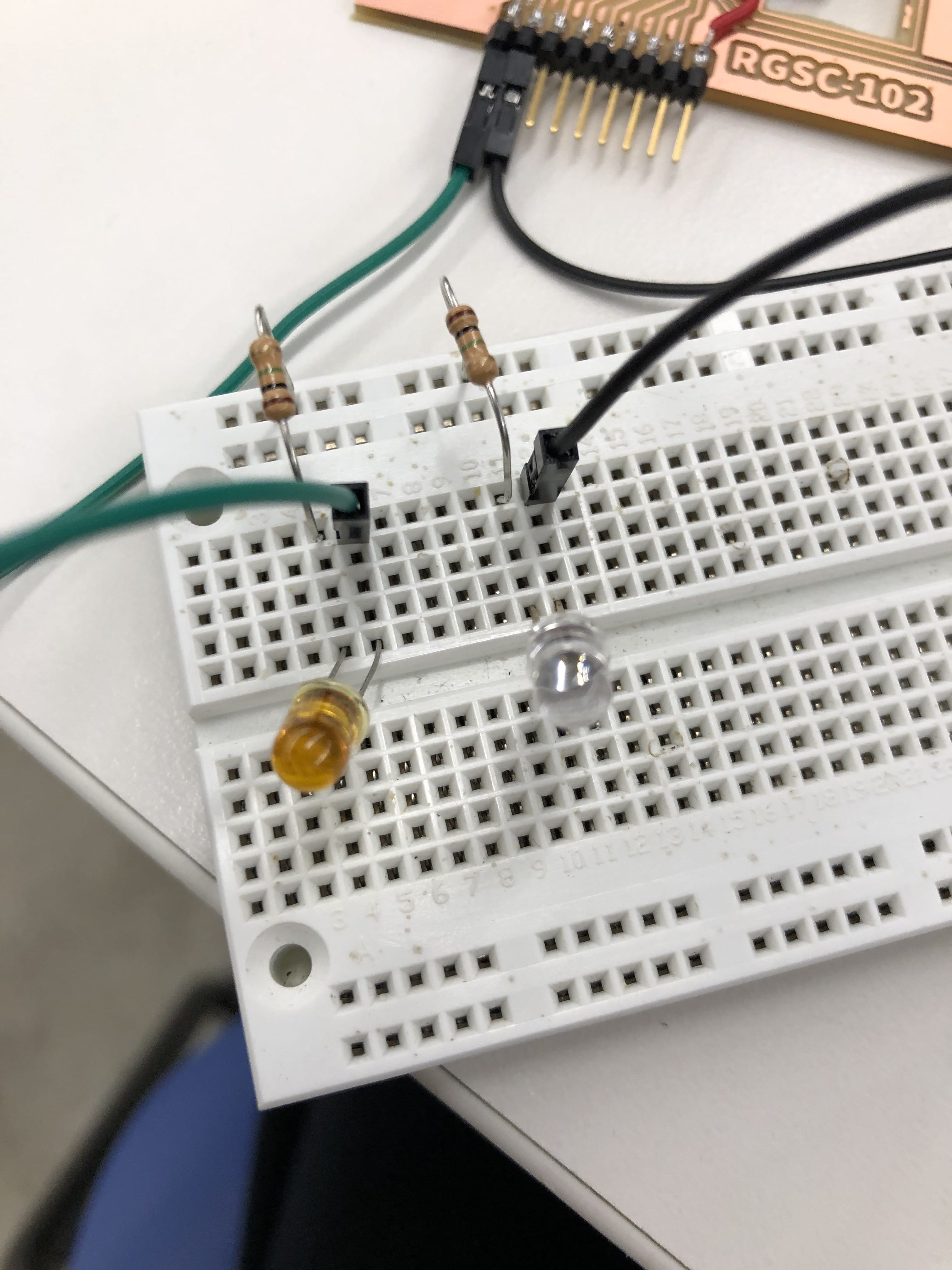
I was able to use my ESP-32 board that I made 2 weeks ago for this week’s assignment. I set up the breadboard so that I could use my web server to turn on two separate LEDs. I read a couple articles to understand how breadboards worked, and ended up using 300 ohm resistors since the lab didn’t have any 330 ohm resistors left.
Building the Web Server
I used the code attached below to be able to create a web server using my ESP32’s IP address, and connected it to my phone’s personal hotspot.
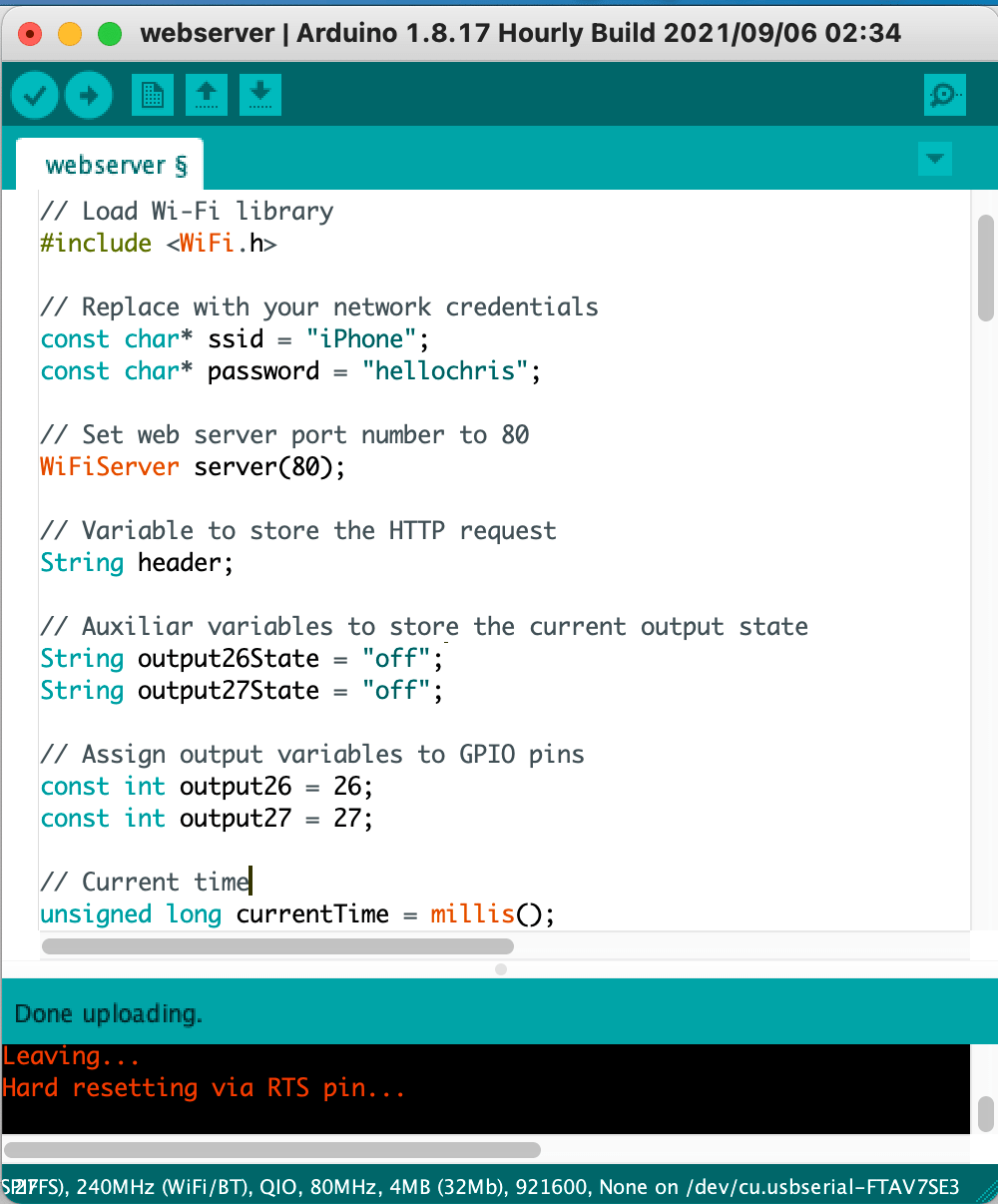
Here is this week's code, which I modified with my pins and wifi SSID.
The code uploaded smoothly onto my board with an FTDI cable, and I attached pins 26 and 27 to the breadboard and ran the program. I opened up the web server by pasting my ESP32’s IP address into a chrome tab, and also connected my computer to the same hotspot as my board. I pushed the button to turn on the LED, but sadly, nothing turned on. I checked my serial output, and everything seemed to be working fine, so I began troubleshooting the hardware and software to find the problem.
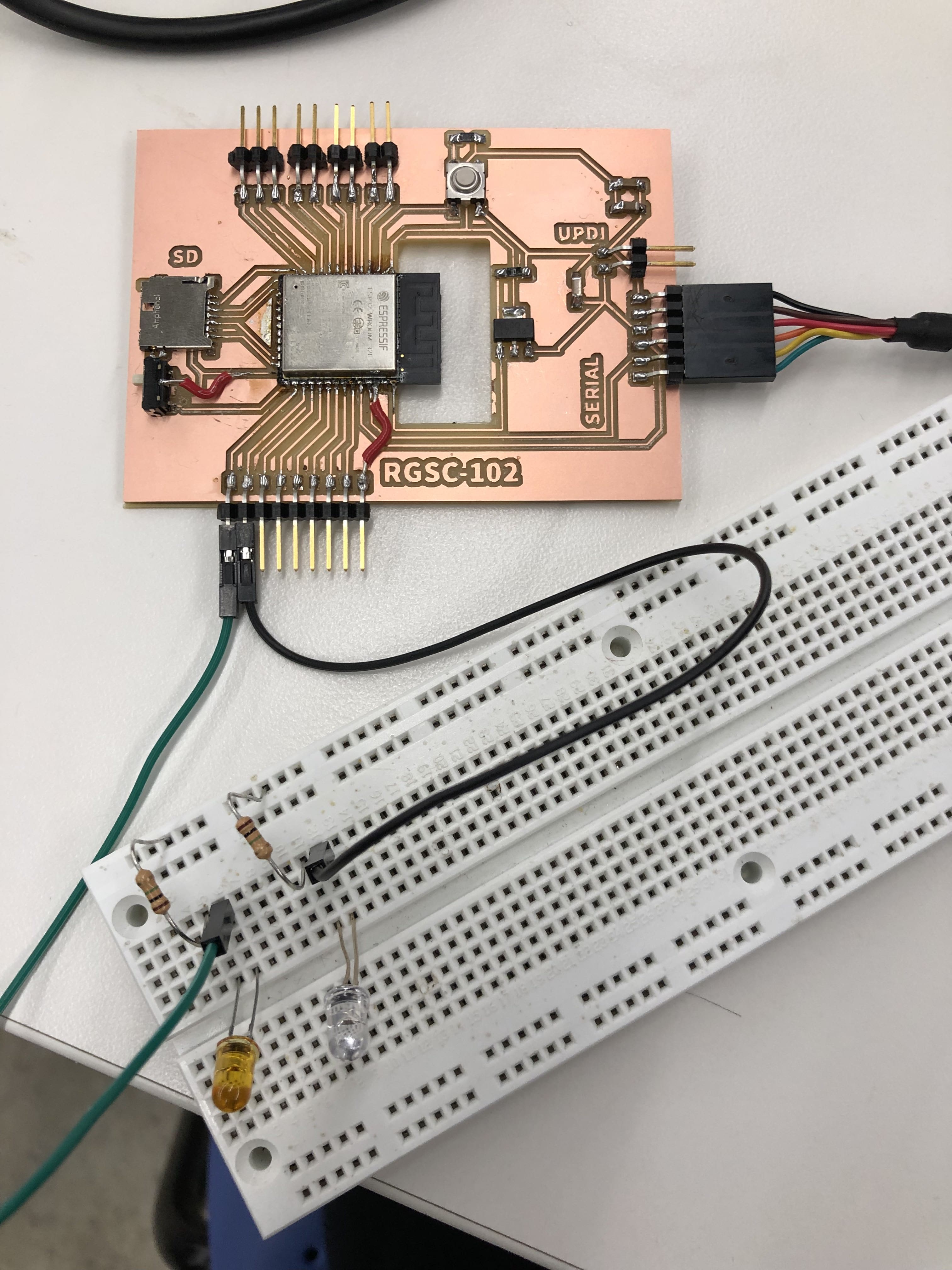
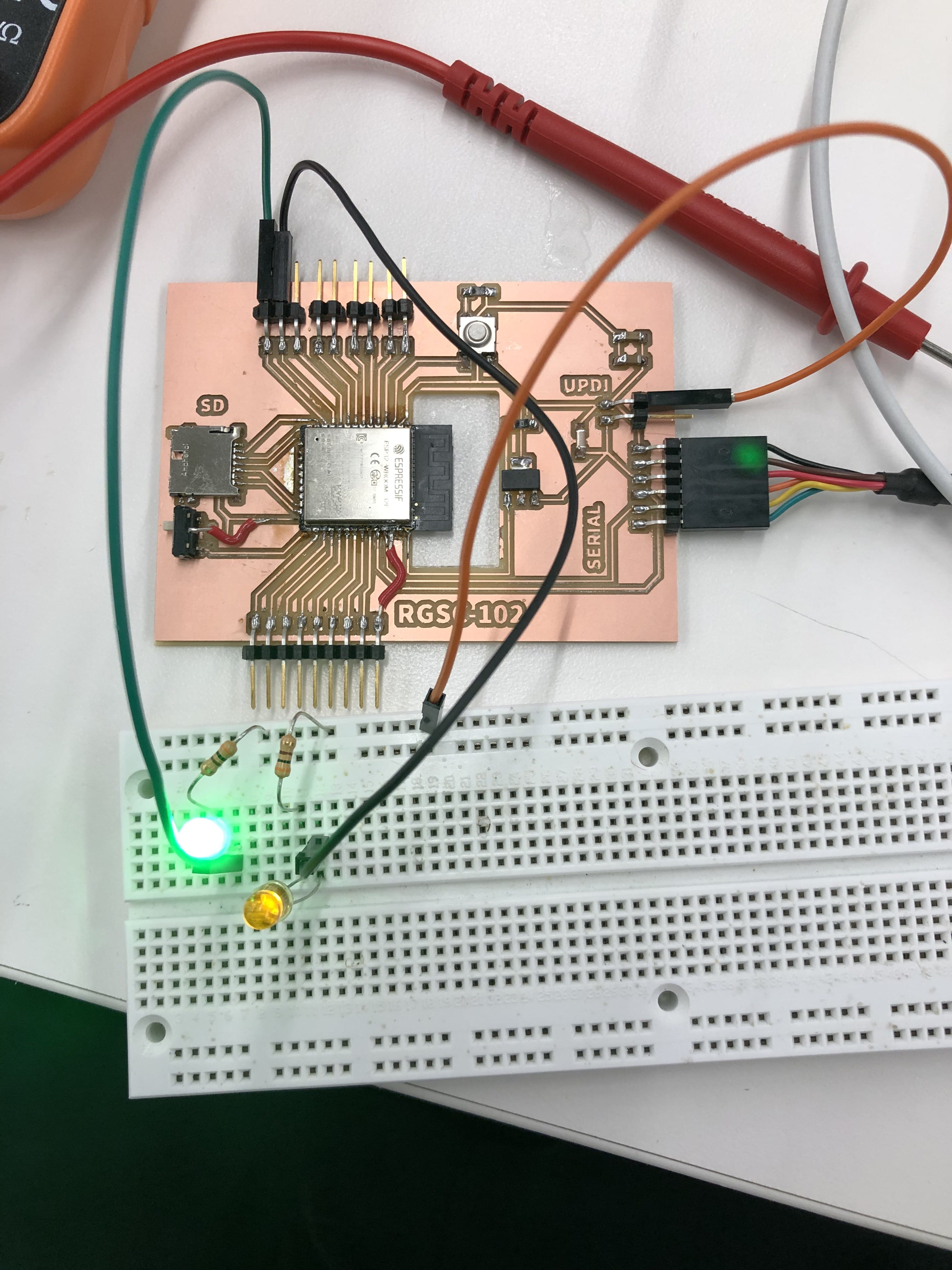
Here is the board setup
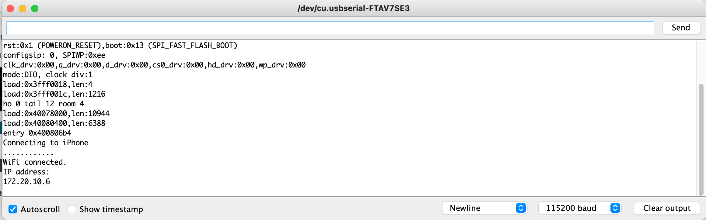
Verifying wifi connection
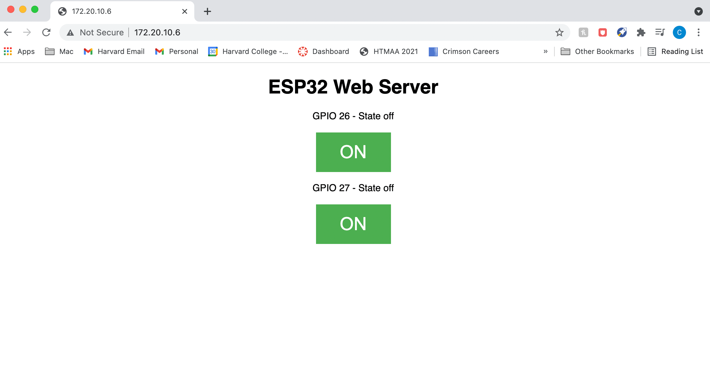
Here is what the web server looks like. For my final project, I will probably style it and add a scale to move my kinetic sculpture.
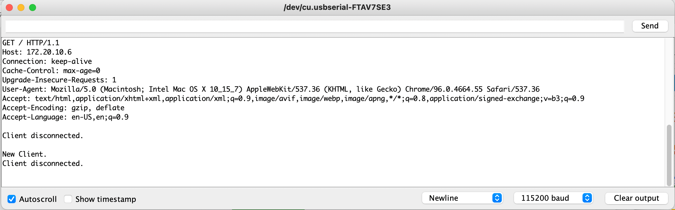
This is the serial output that occurs when the button is pressed on the server.
Troubleshooting
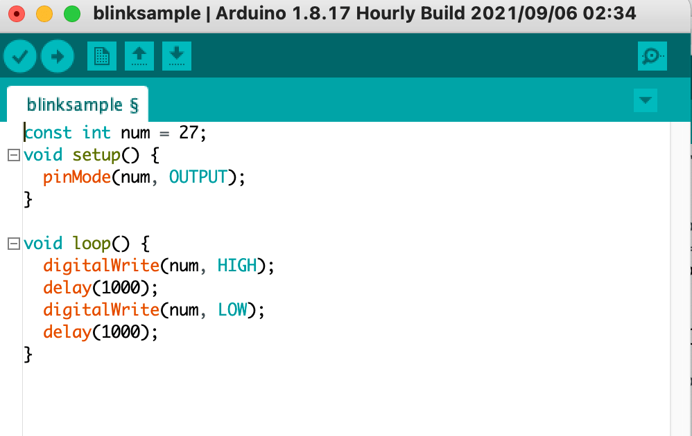
After connecting everything, the LED’s weren’t turning on, so I first tested the hardware by using a multimeter to check my board. I first switched the pins 26 and 27 to pins 36 and 39 in my code, and reattached the pins to see if this would work, but for some reason this still didn’t allow for the LEDs to turn on. I then inspected the hardware by using a multimeter to see if there was voltage running through pins 36/39 by placing one end on the VCC pin(the red cable) and the other on the pins. However, there was no voltage running to the pins. I then tried switching the pins to 5 and 8 in my code, and after reconfiguring my board, I tested the pins again with the multimeter, and to my surprise, there was voltage running to them. However, the LED’s were still not turning on, so I then created a simple blink program to inspect the LED components.
Neither of the LED’s turned on for pins 5 and 8, so this allowed me to realize the problem was likely due to the breadboard. I asked Rob to take a look at the breadboard for me, and although the setup was correct, I was using 10M ohm resistors! Someone in the lab had put a large handful of these mixed in with the 300 ohm resistors, so I was obviously very frustrated and ended up resorting them into the correctly labeled box. After replacing the resistors, I ran my blink program and the LED’s finally lit up, so despite working previously, the resistors dimmed the LED to a point that I couldn’t see them. I then switched the pins back to 26 and 27 just to inspect the original pins, and they also worked!
Strangely, however, pins 36 and 39 still did not work and upon inspecting them with a multimeter they were still not receiving any voltage. I then ran the program with pins 26/27, and both LED’s were able to be turned on and off with my web server. Success! I want to look further into why pins 36 and 39 didn’t work. This could be intentional by design for some reason, but could also be due to additional hardware/software issues that I haven’t discovered.