Week 9: Input Devices
Assignments
This week’s assignment was to measure something: add a sensor to a microcontroller board that I designed and read it. My final project has a clear output of a moving wearable sculpture, but the input is more or less just a button that could possibly connect via bluetooth to my phone. Regardless of what I choose to make my input, I wanted to learn to make a capacitive sensor, since it is a very versatile input similar to a stepper, but much more straightforward and easy to add onto existing boards. I chose to redesign a SAMD11C-blink board because Rob told me it would be more convenient to program, as it didn’t require a programmer after being bootloaded. The existing schematics also made it easier for me to add space for an extra resistor.
Design
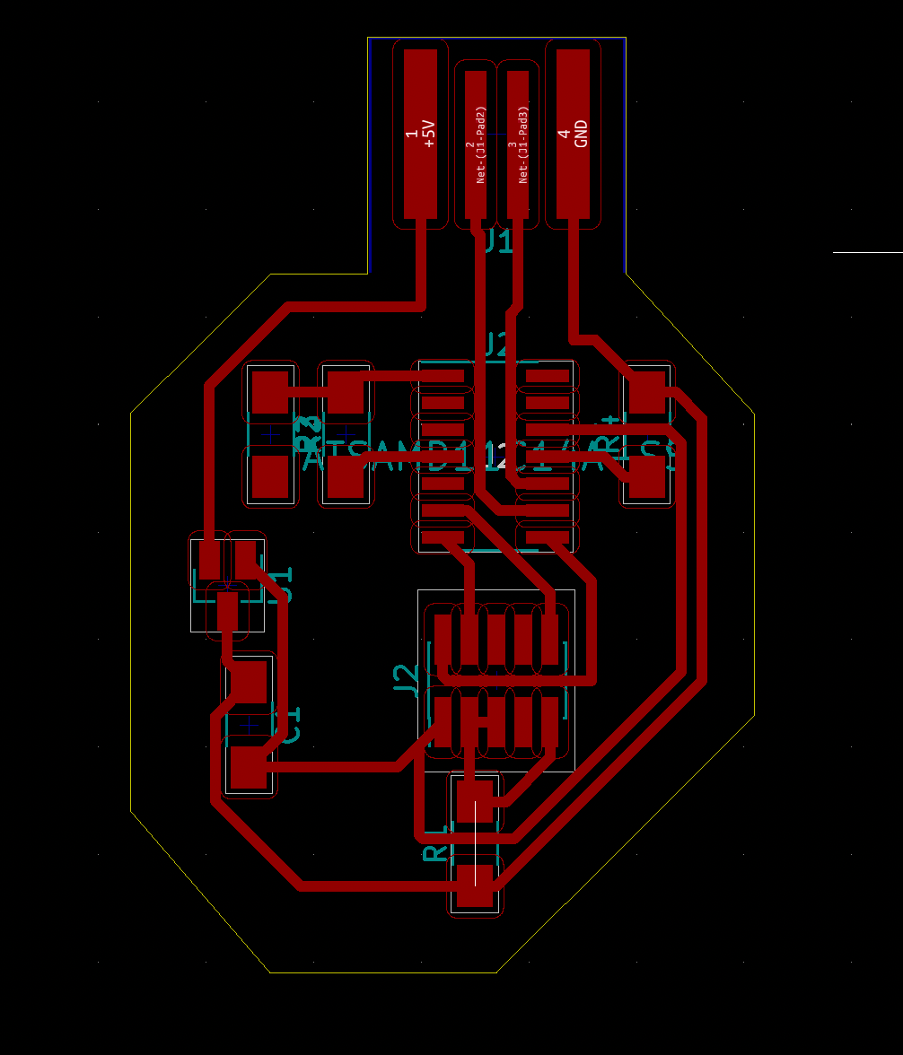
To begin, I brushed off my KiCad skills and created the schematic. To connect the touch sensor, I wired a 1k resistor to 2 available pins(5 and 14), and then wired one end of the 1k resistor to another resistor(this is because I wanted there to be a trace for me to solder on the wire that connected to the copper plate, not because I was planning on adding an additional resistor). After this, I mapped the traces, which took a considerable amount of time because my trace width was .500 mm instead of .4 in the original blink board schematic, which meant that most of the routes were different and that I had to use 2 jump resistors to get everything to connect.
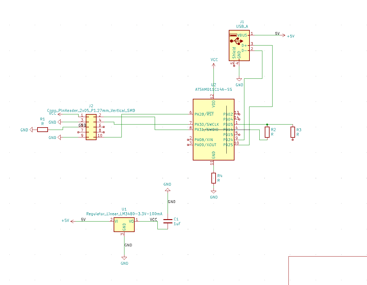
Finally getting the hang of using Kicad.
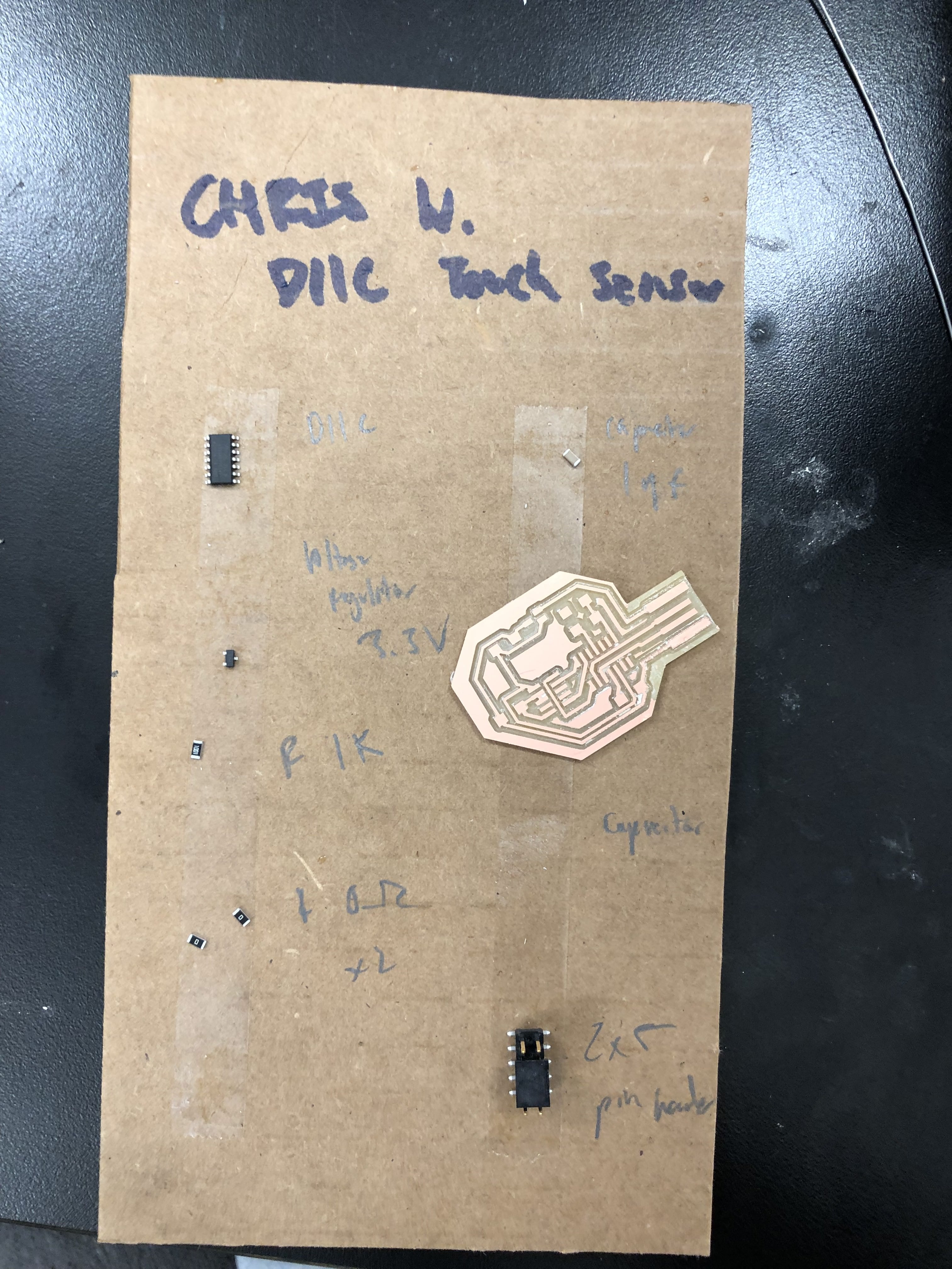
Board Fabrication
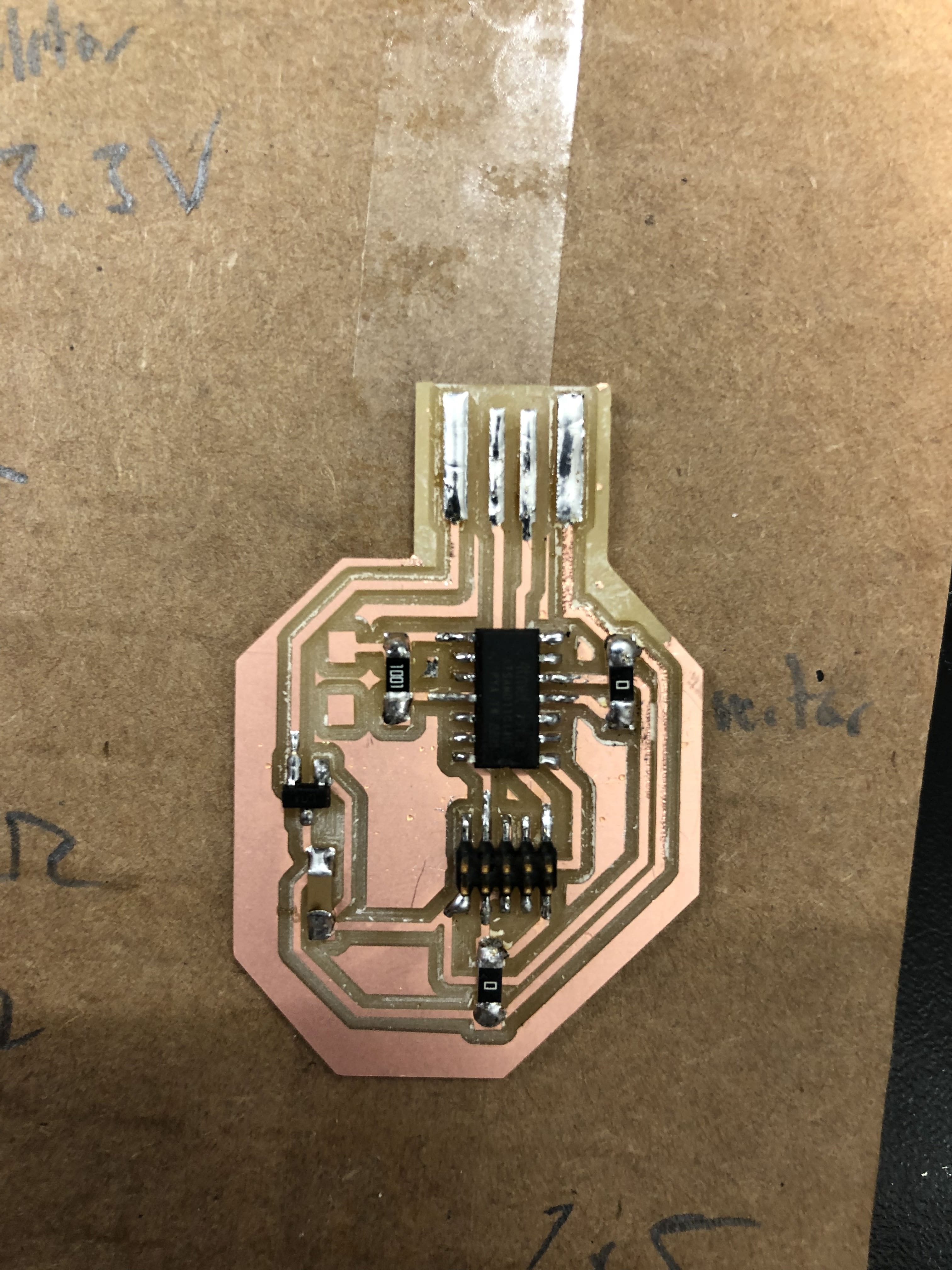
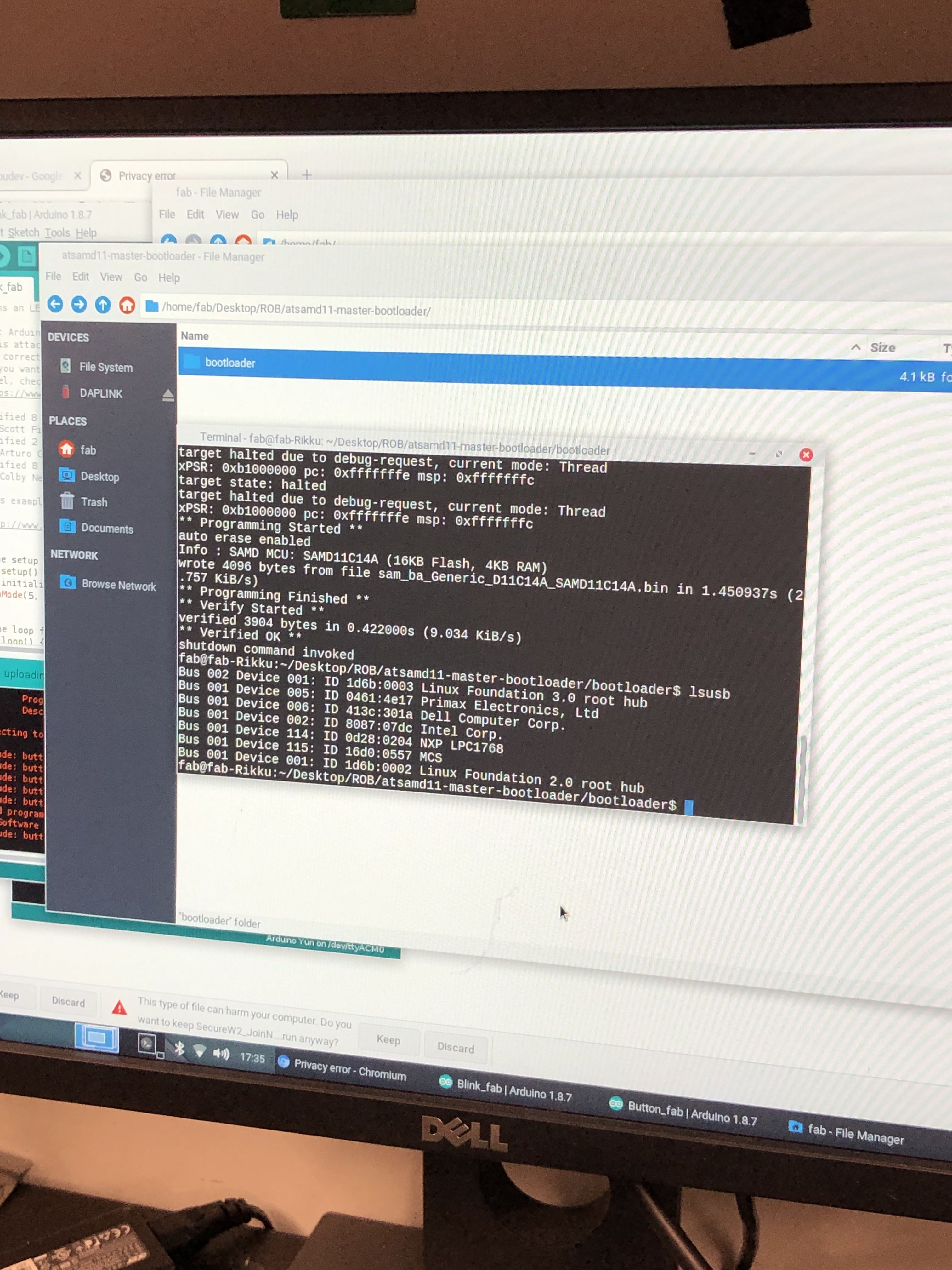
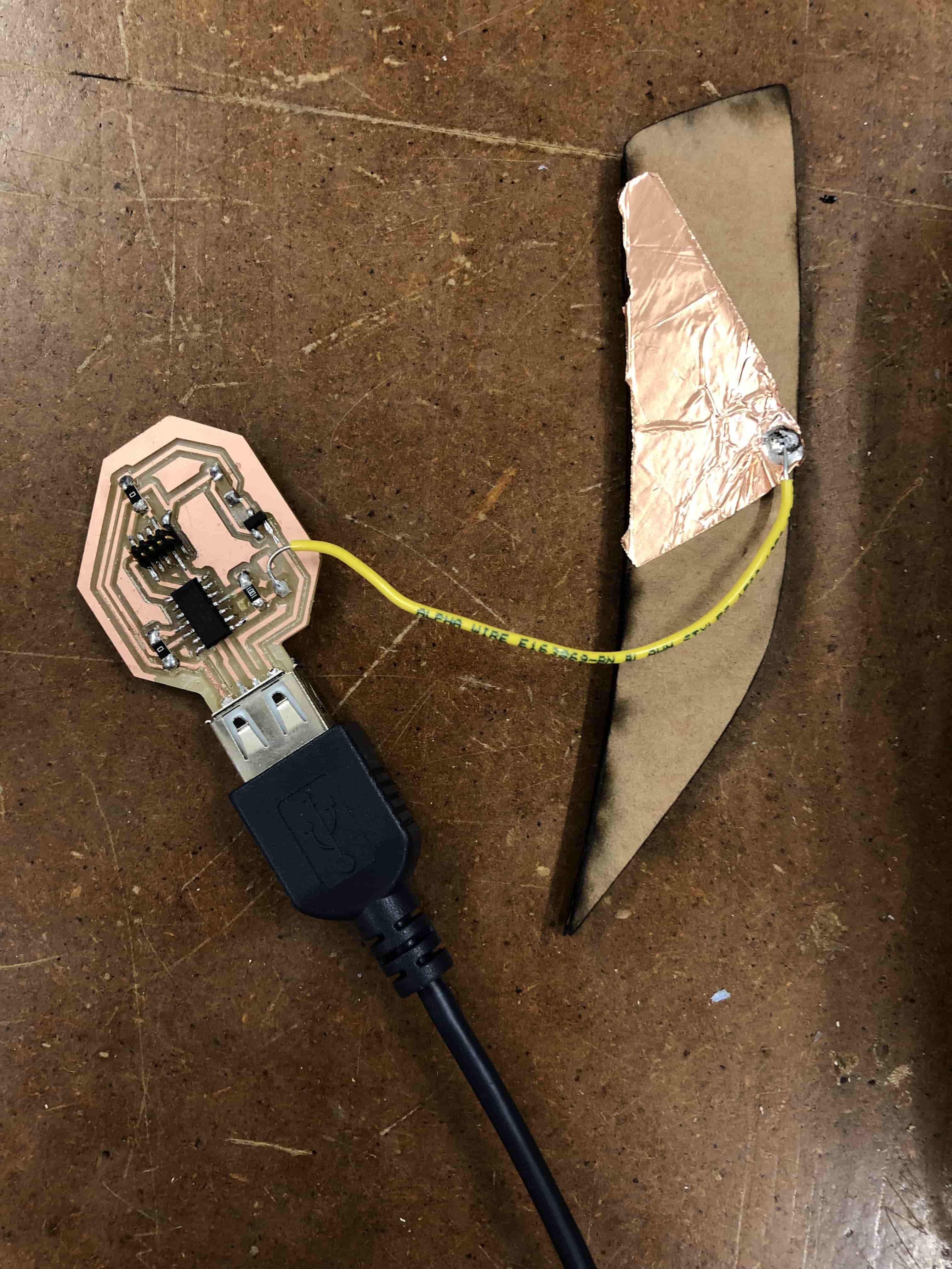
After exporting the trace files from inkscape, I milled the board and soldered on all the parts, and everything so far was going smoothly. I asked Nathan to help bootload my board, and it successfully bootloaded when we tried it! I soldered on a wire to one of the pads I had connected to the resistor and then soldered the wire to a piece of copper. Piece of cake, right? Wrong.
Programming
I connected the board to my computer and downloaded the Fab library boards to use a SAMD11C. However, after running Rob’s sample code and downloading the capacitive sensing library, the code wouldn’t compile for my board. After speaking to Rob at office hours, we found out that the fab library’s capacitive sensing library was not compatible for D11 boards.
Troubleshooting
So... I tried to use an Arduino library, which didn’t work because it was incompatible with the D11 microcontroller. Instead, I need to write my own program to do touch sensing. I used the barebone code that Rob had given me, and I tweaked and annotated it so I could make my board functional. Success! It ended up working out, and I ended up writing this code. Basically, I needed to make the charge pin HIGH and LOW and measure how much time it took for the sense pin to change its state. The for loop reads input/read pin 5 after setting the output/charge pin 4 to HIGH, and if it’s low, nothing happens, but pin 14 is set to LOW, and if it is HIGH, nothing happens. The time it takes to loop through this rapid state change is recorded.
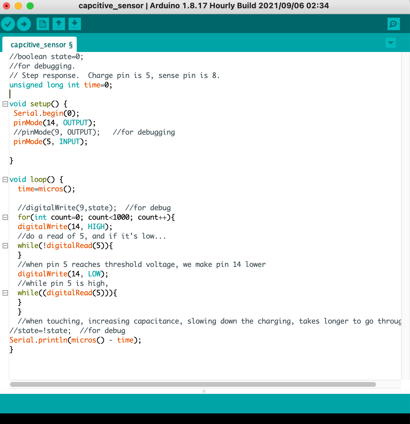
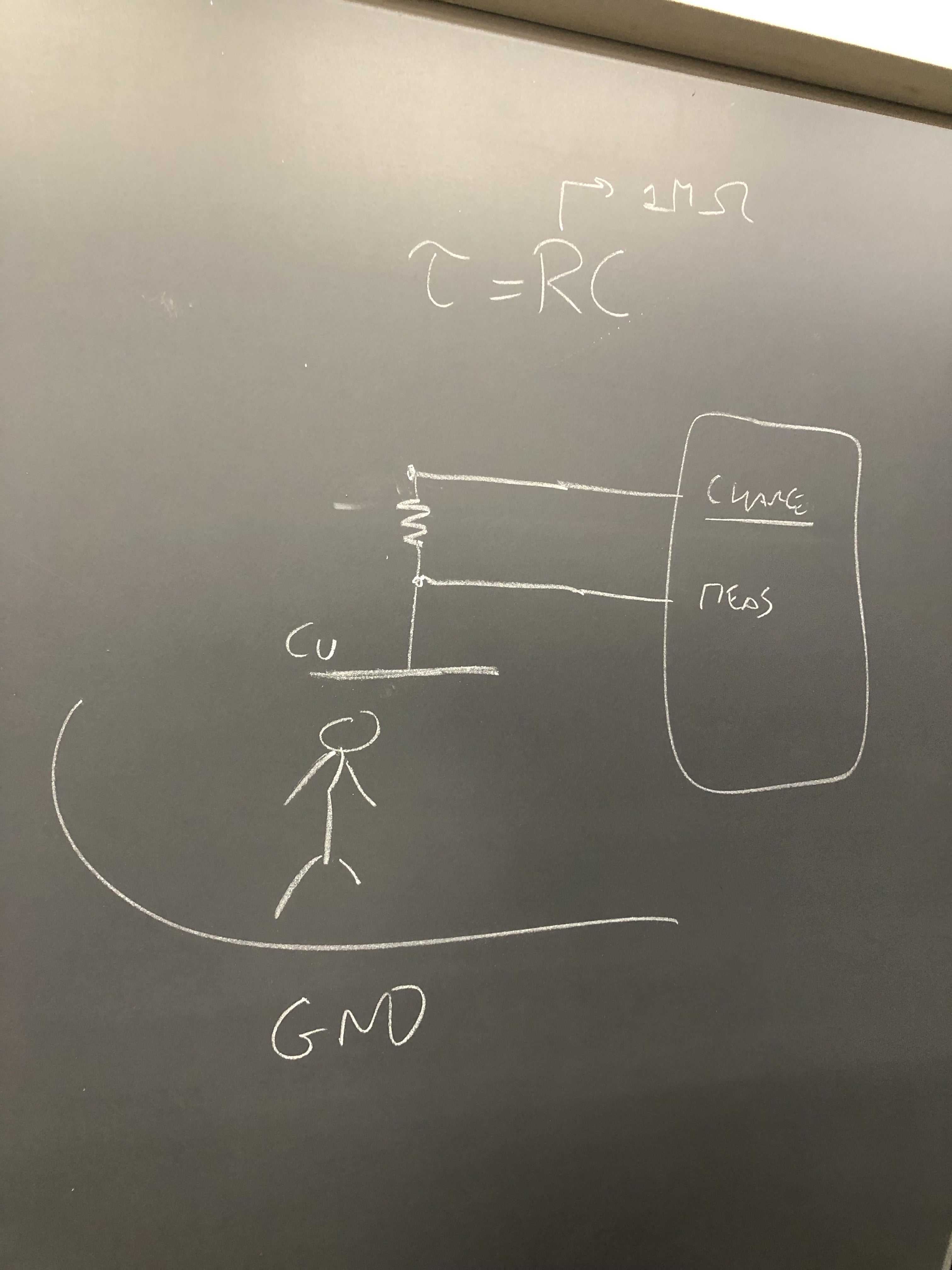
When I touch the copper sheet, I increase the capacitance, which slows down the time it takes to charge the pin, which leads to a longer time in the for loop. The loop is 11700 microseconds before I make contact with the copper sheet, but doubles to around 28500 microseconds during contact. In the future, I can code an output with this by setting a while condition for a time exceeding 25000 microseconds.
 Touch Sensor Board(KiCad Project .ZIP)