Week 10: Output Devices
Assignments
This week’s assignment was to add an output device to a microcontroller I designed, and then program it to do something. Because my final project will use motors, I decided to attach a servo motor to a board and then program it to rotate. Initially, I built the servo board on the website with a D11-14A microcontroller, but after an accident in the lab, I decided to attach a servo to a microcontroller I made last week.
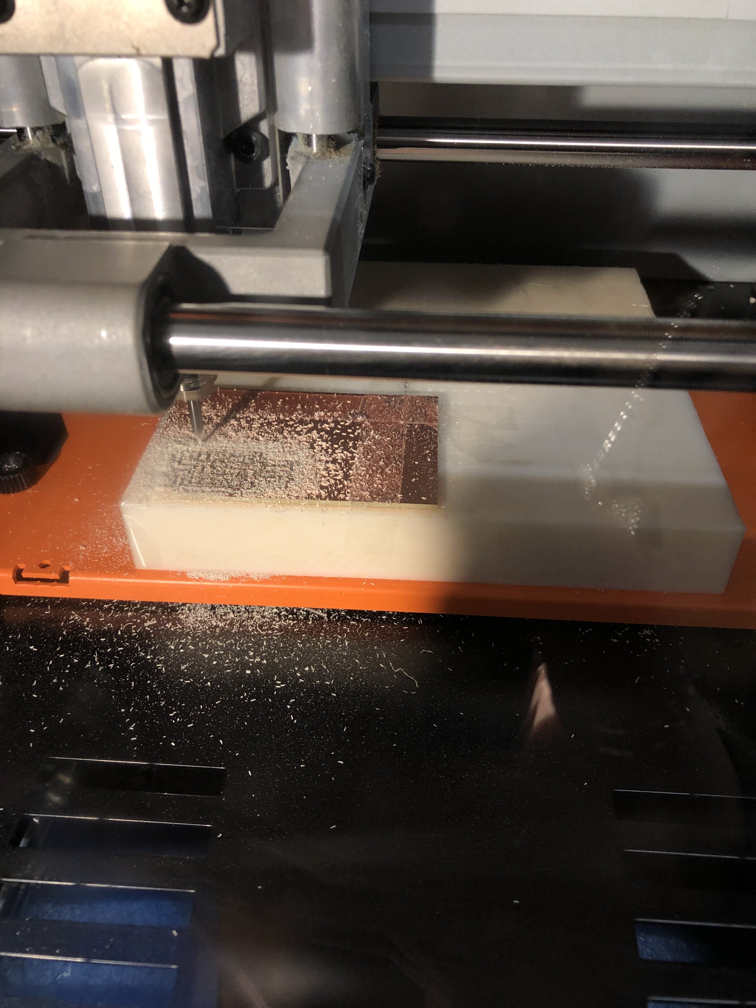
Preparing the Board
I chose to use this board with the servos this week. I downloaded the PNGs and milled the board, and then proceeded to solder on the parts. After this, I needed to bootload the D11, which I realized would be more complicated than normal because we didn’t have a female 2x2 4 pin connector for the bootloader. The 3x2 header is ISP configuration for an AtTiny, which converts from the 10 pin DAP configuration to ISP, but I want RESET, SWCLK, GND, and SWDIO in the configuration below. After consulting with Nathan, I used help from Ibrahim and his 2x5 to 2x2 converter board in order to bootload my board. We drew a diagram to match each pin connector individually to the pins on my board to bootload it, but we ran into problems and it still unsuccessfully bootloader.
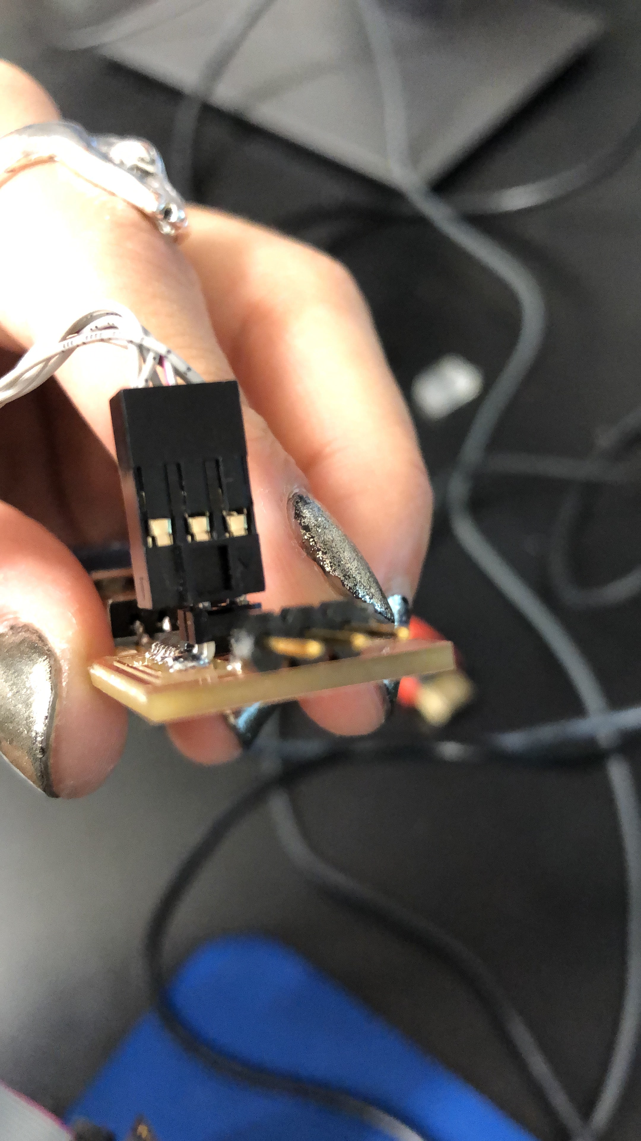
Here was the problem with the misaligned pins
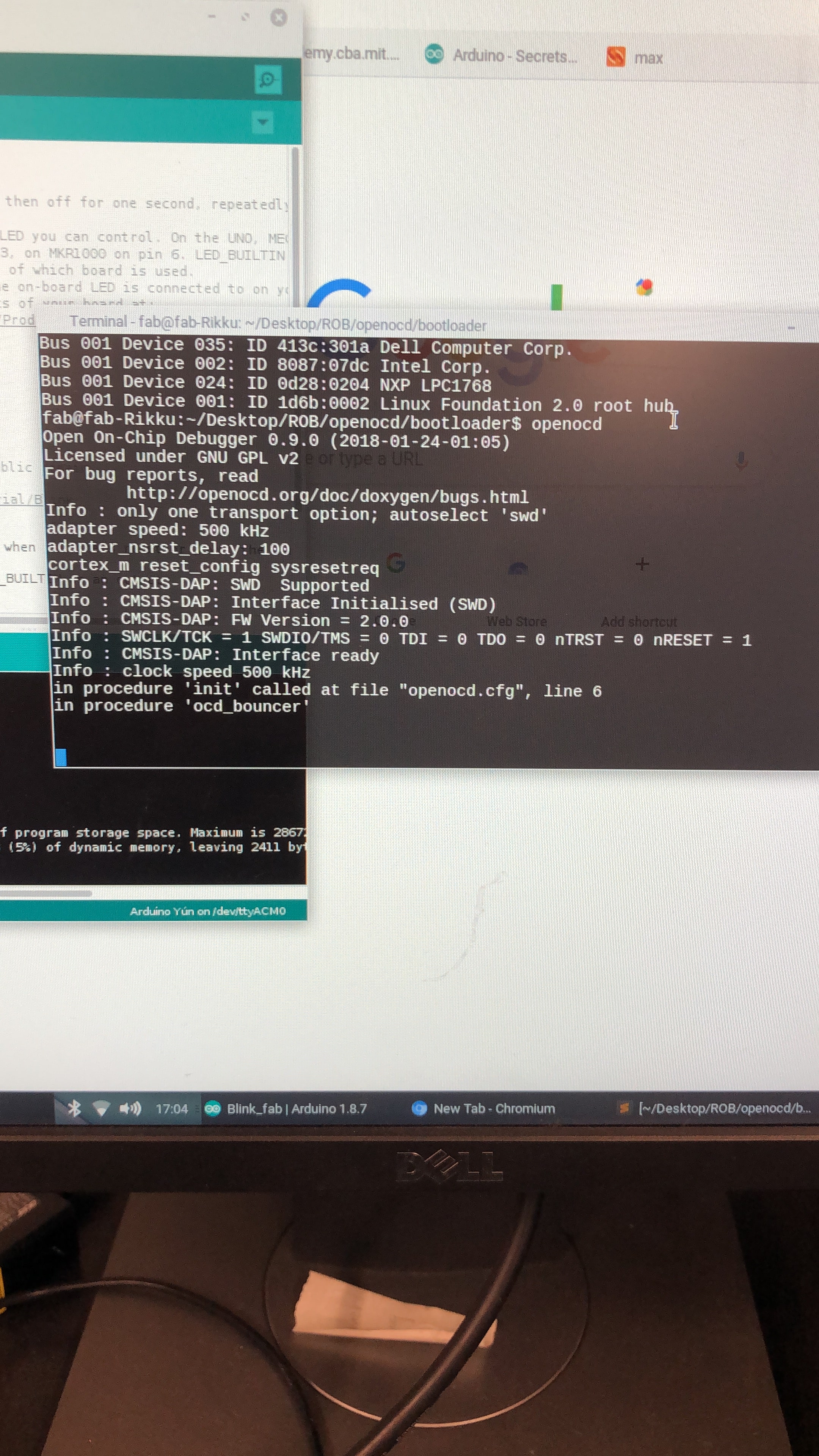
Here is the bootloading not working from the computer
The Accident
I left my board connected to the USB cord with a USB attachment soldered onto the top of the board by the computer, as I had planned on coming back after my next class to continue troubleshooting. I couldn't solder the USB lower on the board because the trace outline was too thick to fit inside a USB port, so it was slightly fragile. However, when I returned in the afternoon, someone had ripped my board out of the USB cord, and had ripped off the USB attachment head from my board. This caused many of the traces to peel off, and the traces were too hard to be able to solder on small wires(I definitely made several failed attempts). In the end I decided to take my board from last week and attach a servo motor to it.
Repurposing an Existing Board
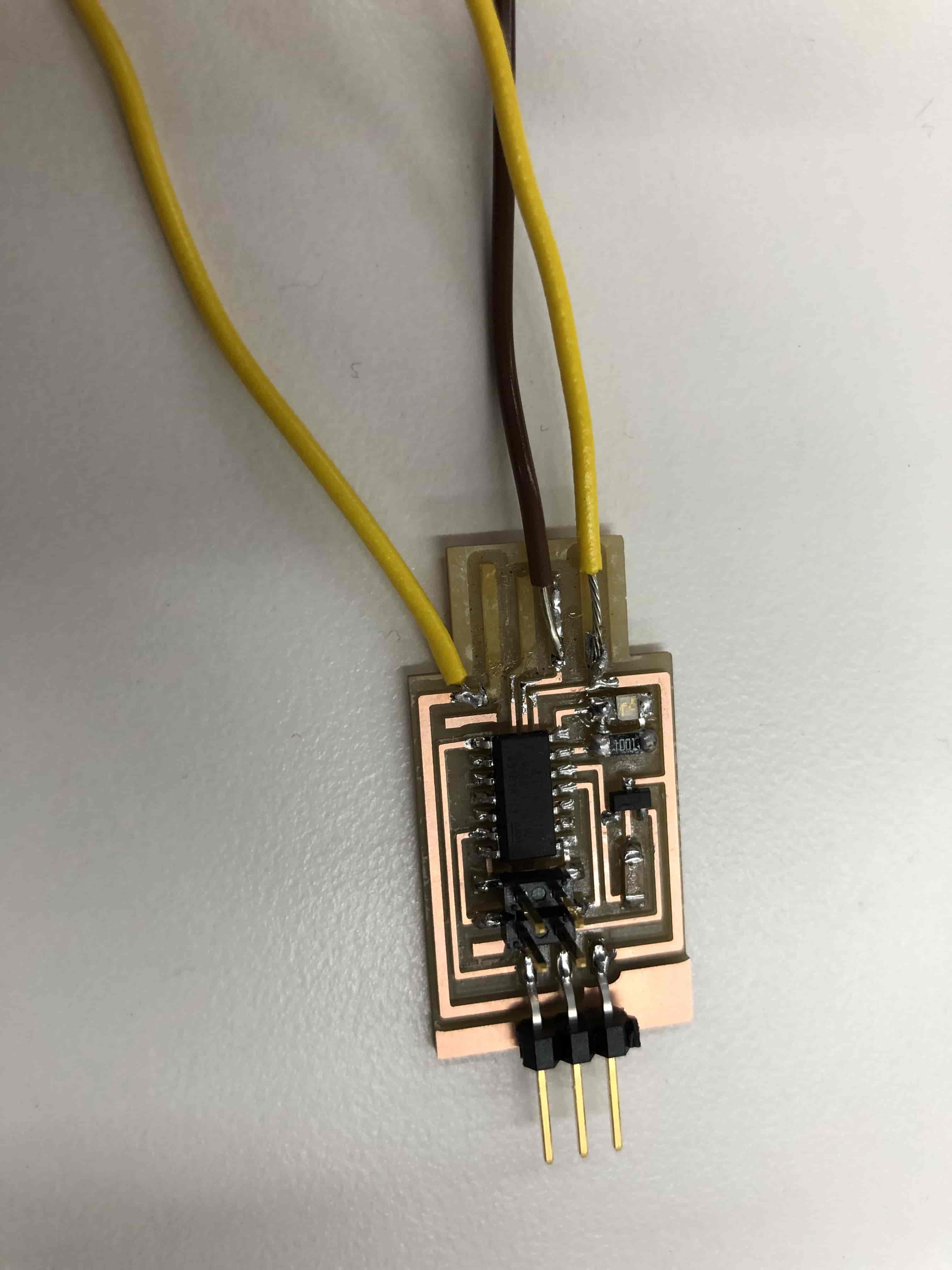
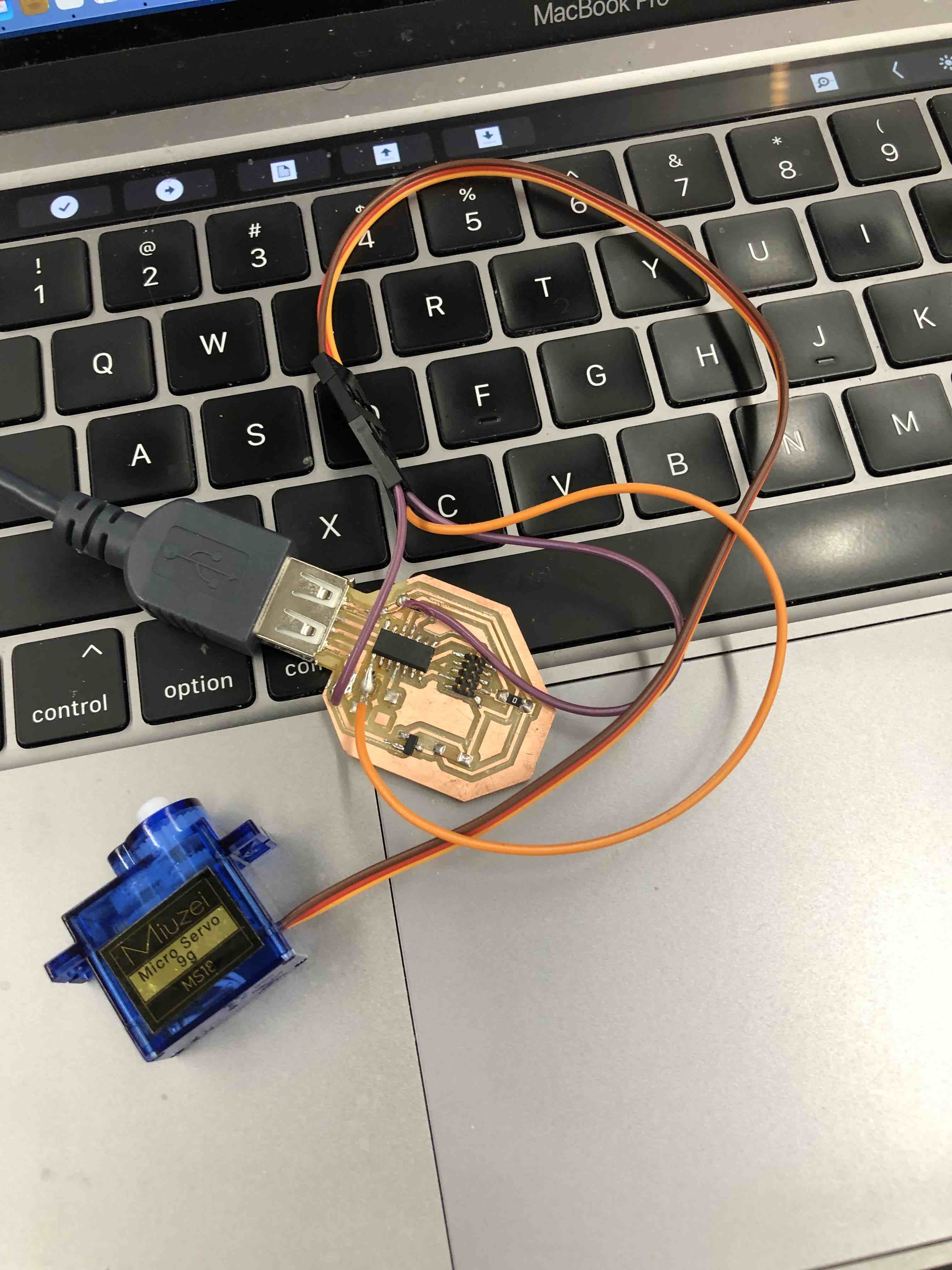
I knew that the board I designed for capacitive touch sensing could work with a servo, as the servo only had three pins: ground, power, and communication. I had a pad on my board that would allow me to attach the communication pin to an available pin on my board(pin 5/A05), the same pin I used to attach my copper sheet for capacitive sensing. I removed the resistor that bridged the pad to another pin(14), and then soldered on a male wire pin to the pin 5 pad. I then attached male pins to a trace that led to the power, and then another that led to ground. I connected the servo pins to the 3 I just soldered on.
Programming
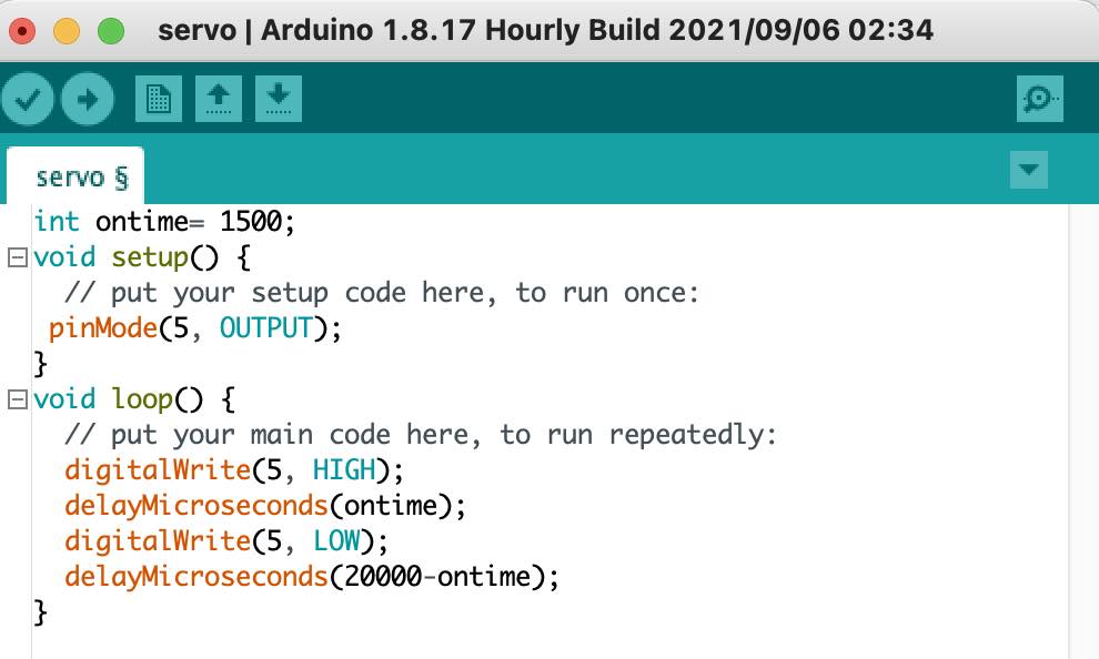
Sadly, Arduino’s servo library isn’t compatible with D11 microcontrollers. Bummer(don’t think I’m using D11s for my final project). I ended up using Rob’s help to write my own program to get the servo to operate. The code below is similar to what I wrote last week, but I delay switching the charge pin from HIGH to LOW repeatedly to make the servo arm sweep 180 degrees back and forth.
Troubleshooting
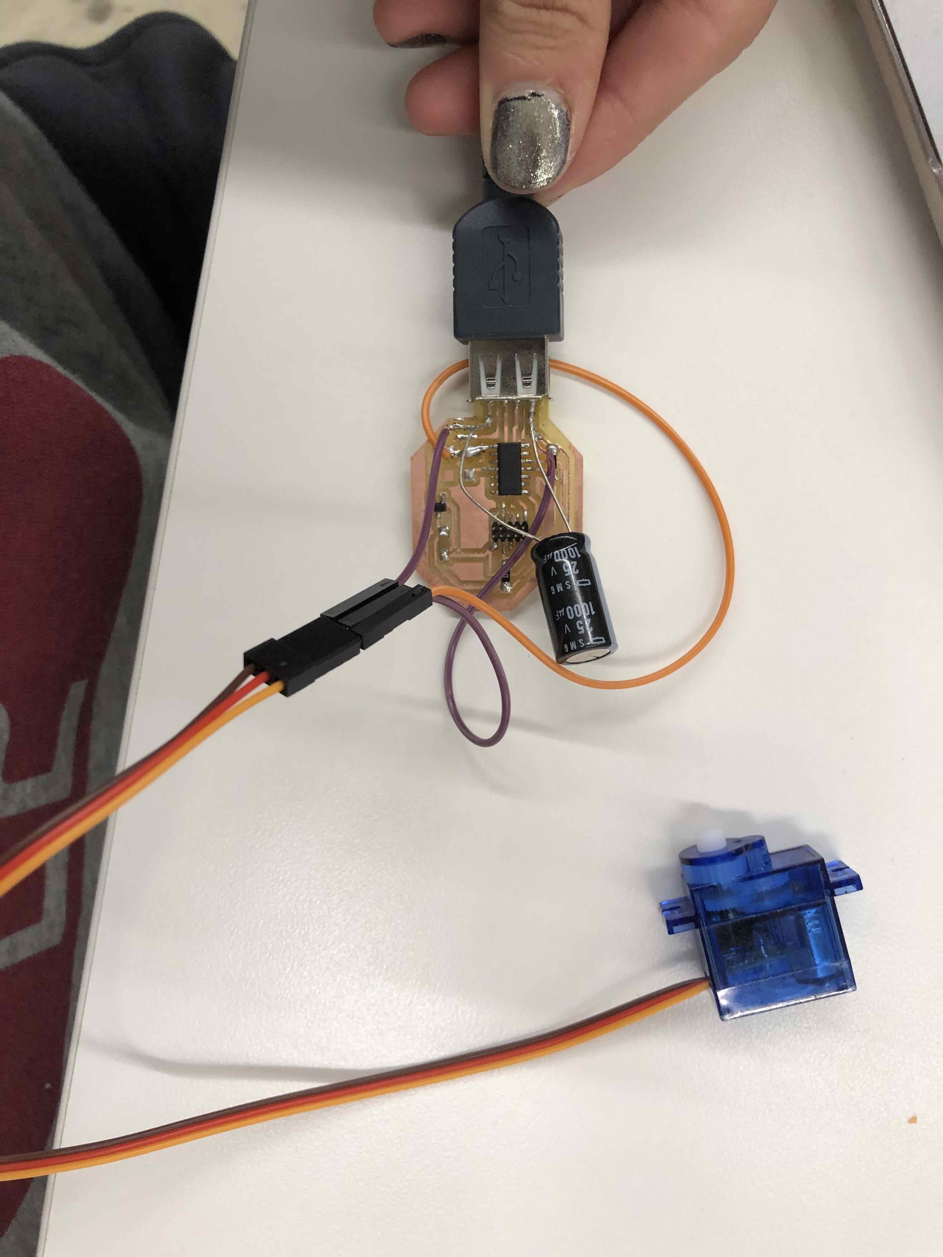
The board was not able to accept the program from my laptop, and the light on my USB adapter attached to my laptop started blinking, meaning that something was short-circuiting. I unplugged the servo from the board, and my computer immediately recognized it again in port from arduino tools(it had disappeared before). I realized that the servo was probably using too much power initially, so Chris Zhu told me to solder on a 1000µ capacitor to the ground and power traces.
Running the Program
The program finally uploaded to my board, and my servo was vibrating and whirring. I assumed that it was moving in place given my program, so I tweaked the numbers based on the data sheet where my “ontime” variable would be 1500 microseconds, which would change the delay after the charge pin changes. After uploading, all of the sudden, my board was no longer recognized in the port. I tried to restart the arduino program, disconnecting and reconnecting the servo and the board to my laptop, and even replacing the servo, but nothing worked. Rob and I continued troubleshooting, but it seemed like there was something wrong that we couldn’t identify. Ibrahim also used servos and D11s, but he also was having issues getting his servos to work. I decided to rebuild a board with a servo output for my final project, but with an ESP-32 microcontroller the following week. I spent the rest of the night routing the traces with Gabby and Suvin :)