Zijun Wei - How to Make Almost Anything
ProjectLog.
Concept (Week 1-4)
The first idea is to create a gadget that can expand when in use, and reduce its form-factor after use. It can be a wearable device like the iron-man gauntlet , activated with one touch.
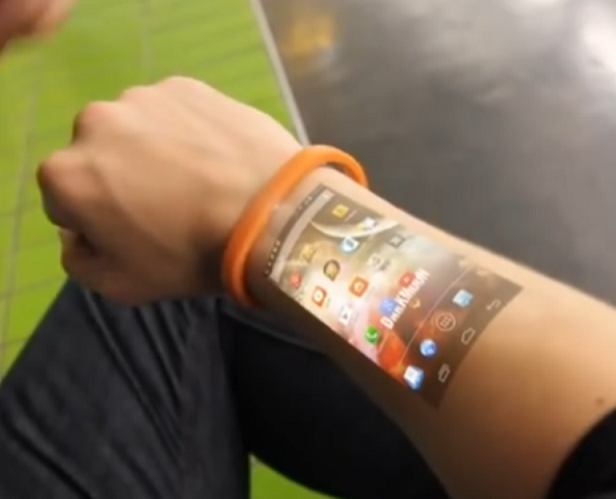
In terms of functionality, I will start with a wrist touch display, or a projector with motion capture camera, like the Cicret Bracele. The content will be wireless transmitted to this gadget for remote control and manipulation.
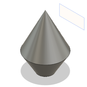
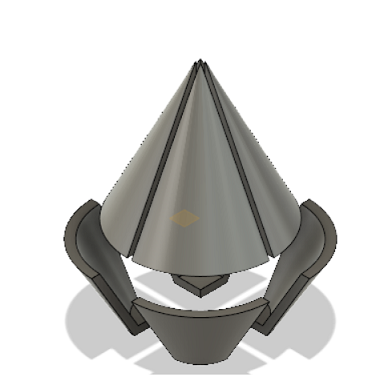
The second idea, a bit related, is a stand-alone drone, which changes shape, navigates and responds to human language. I found this Hexmorph, which has the reconfigurable character that I would like my drone to have. Some very basic conceptual sketches:
In all, this will be a reconfigurable, speech-controllable drone.
Refining Concept and rescaling scope(Week 8)
Gesture-controlled projecting interface.
Components: 1. Input: Motion-capture camera with visual recognition/IR sensor arrays/laser distance sensor arrays/accelerometer module; 2. Output: Projector/Hologram projector/cheapo DIY phone hologram projector with magnification;
Modification of scope(Week 9)
The original idea of generating image through a project seems a bit too ambitious for the time given, as hardware-wise, I need to find a projector with the right form-factor and interface, not to mention the power source, and software-wise, pixelating a quality video will require much more time than just c-coding the mirco-controller.
To come to a goal achievable within the time frame, while maintaining the gesture control for the input part, for the output part, I am thinking of doing motor control, and I will make a wireless interface between the input/output subsystems.

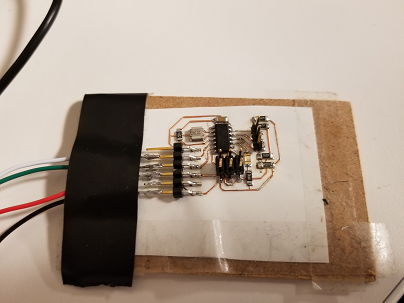
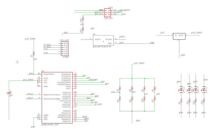
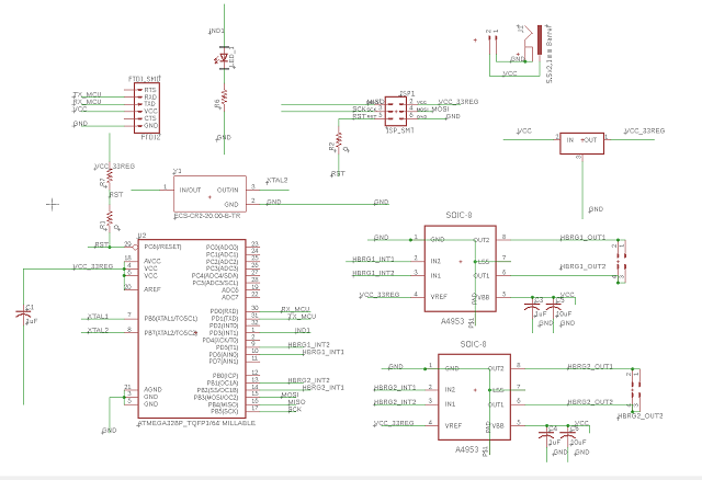
To test the related components, I made a test board incorporating a laser distance sensor, a gyro and an h-bridge. After identifying the pins for I2C communication and timer/clock output, the schematic design was straighforward. One thing that I was concerned about is that, while I would like my h-bridge and MCU to run at 5V, the sensors are designed to run at no more than 4V. I separate the sensors and the h-bridge+MCU into two subsystems, sensor-system(SS) and power&control-system(PCS) and use two voltage regulators, 3.3V and 5V, to provide power for them respectively.
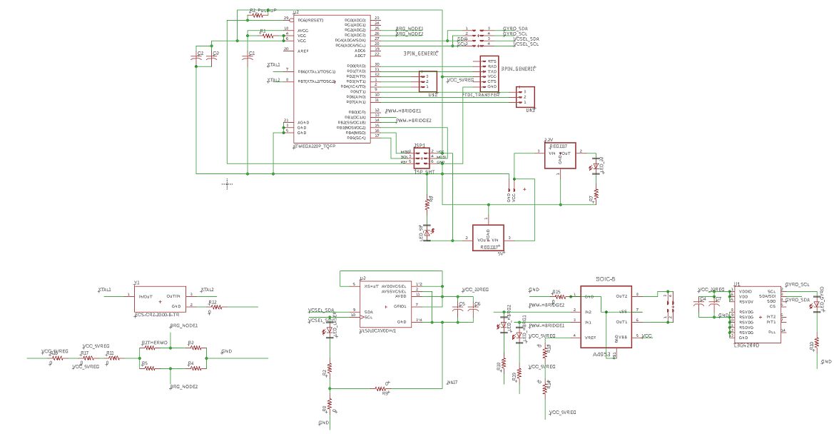
Some minor notes for the subsystems: 1. I use blue LEDs for the sensor subsystem with 500ohm resistors, and red LEDs for the h-bridge+MCU subsystem with 1kohm resistors, to indicate the power and communication status 2. I chose ATmega328p AU as the MCU for its larger memory and higher number of pins, as compared to ATtiny 3. The ADC on the ATmega328, which I use for a thermistor bridge circuit readout, is power by Vcc through a low-pass filter, which is suggested in the datasheet. The LPF is built with 500ohm resistor and 10uF capacitor, giving a 3dB cut off at ~31Hz.
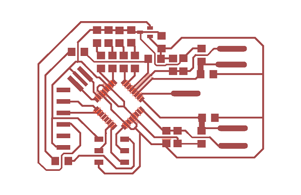
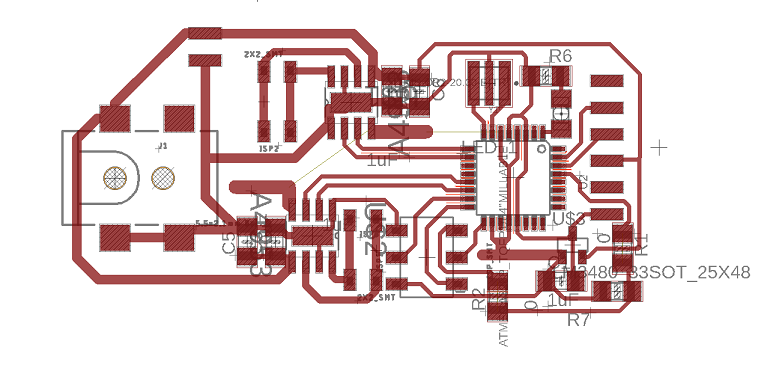
In the board layout, I have come across the complications where I have to rout a wire across multiples wires. I used 0ohm resistors to build bridges, but I am yet to make sure whether the 0ohm resistors will be able to sustain the current running in the PCS, which for a motor, is typically at least 2A.
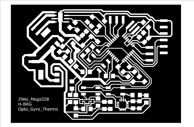
Also I tried to make sure the trace length going throught the two paralles sections in the thermistor bridge the same, so that any potential difference will be due to temperature change in the NTC ideally, given that all the other resistors are chosen according to the NTC. But I have not found a way to precisely set the trace lenght from one node to another in the GUI. Some posts online suggests writing a script to achieve that, which I am yet to look more into.
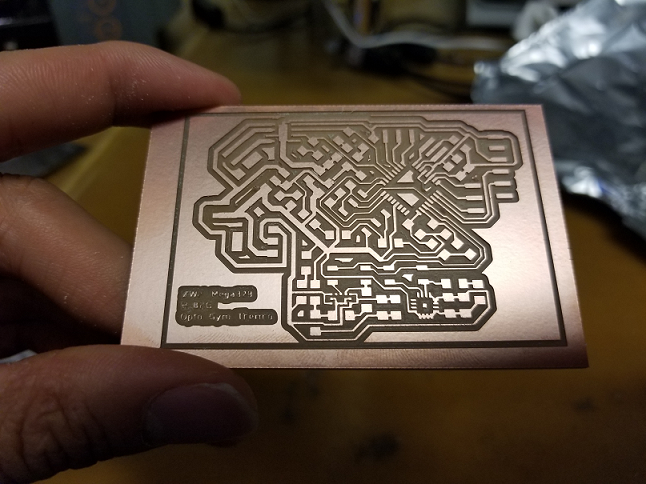
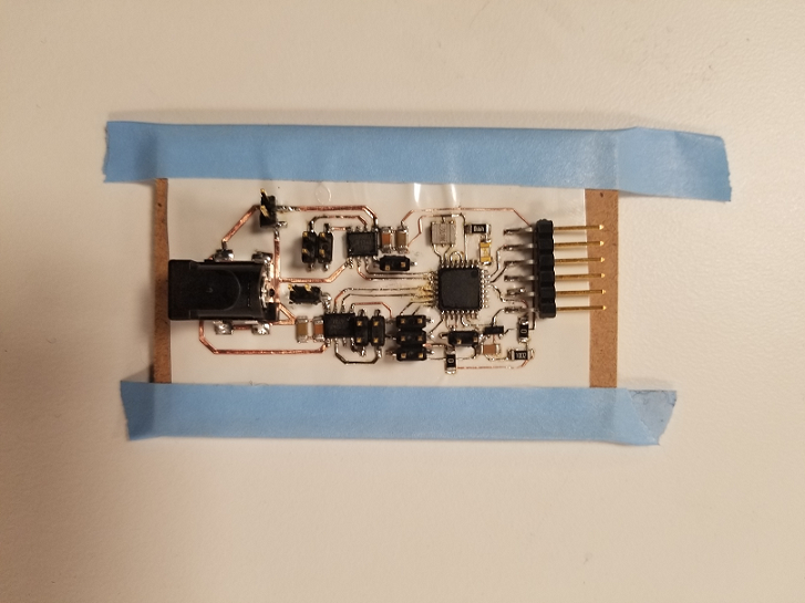
To assemble small-footprint smd, I first tin the pads on the board, and then flux the pads on the chip, put the chip approximately in place, and use hot air gun to melt the solder until I see chip get self-aligned in place.
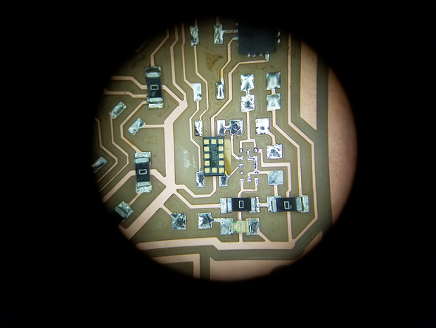
After assembly, I test the regulators, which seems to meet the power requirements, giving 3.28V and 4.99V for a supply of 6V.
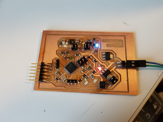
However, logic-wise, I am yet to make sure: 1. whether a switching of 3.3V logic from the sensors can give a detectable switch to the MCU, and moreover, 2. whether a switching of 5V logic from the MCU will damage the sensors. If it turns that either of these will cause issues, I will need to add in a buffer circuit to translate the voltage switching.
In addition, I forget to put in the bypass capacitors to the H-bridge. Yet to test how much that will affect the system.
In the end, it turns out that the board cannot provide enough current to the H-bridge and the motor can give out a noise but not turning. Also for the sensors, although I managed to put in place pull-up resistors in the SCL and SDA lines surgically, as I originally forgot to, the wiring to the sensors have some issues. I will need to redesign the test boards.
Modify output for the final project
My original goal to create a gesture-control interface to hardware/software, and I gave some more thoughts on the goal and the required input/output modality. While the general motion of the hand can be capture by IMU(accelerometer/gyro), the actual fingers movement can probably be captured more easily through capacitive sensing. The output will be a remote control car and computer screen that shows the current control paramters.
The idea is that: 1.Capacitive sensor nodes on my hand joints which capture the relative position of them. Along with this, a accelerometer and a gyro will capture the general motion of the hand to provide extra input modality. 2. All these input will be fed to a local MCU, one for each hand, and sent through a slave network module to a master network unit, which talks to the computer and a car control MCU through serial communication. 3. On the computer the serial input will be processed by node.serial, which feeds into three.js for visual effects
A first sketch for the project is illustrated below:
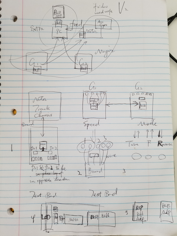
The goal is to build a gesture control mini mobile system.
In this first version, I will have three core components:
The first component is two hand control units, the input, one for each hand, each with integrated accelerometer and capacitive sensing electrodes, all controlled by a local microcontroller. The electrodes will have two parts, one is the transmitting electrode sitting at the palm, the other is the receiving electrodes sitting at finger tips, that help define the motion of each finger.
The second component is actual motor part. I plan to have a small rover that takes in commands and change its motion states accordingly. For triage, I put my focus on the electronics.
The third component is the communication units, which will be sitting on each of the above for inter-component communication.
1. Hand control unit
Starting with the ATtiny45 txrx example, I first make a board using ATtiny44 because I want to do motion capturing for multiple fingers. Ideally, one control unit with four input states can control the directions of the motor units: forward/backward/turn left/turn right, another control unit can control the speed: slow/medium/fast. But I chose ATtiny because the board is relatively easy to make, and thus good for fast testing.
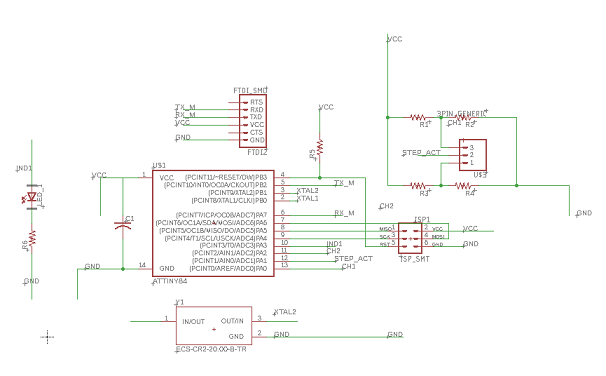
t44 board schematic
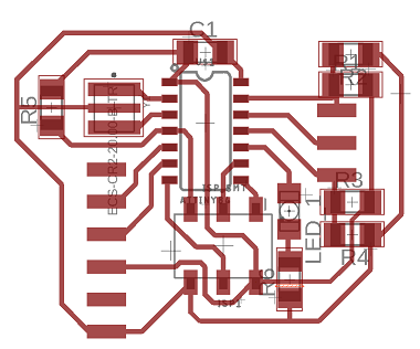
t44 board layout
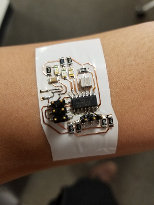
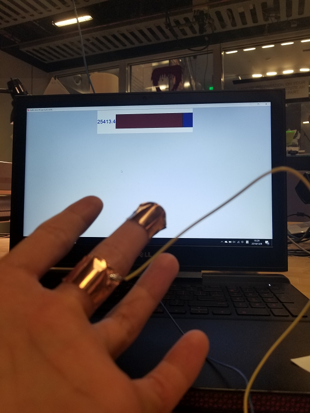
From ATtiny45 to ATtiny44 I only need some pin mapping and clock setting configuration. And using the pythonSerial script I can find an intermediate value for the voltage on receiving electrodes as a threshold, beyond which, the corresponding receiving electrode is considered touching the transmitting electrode and a motion command is triggered. The original idea was to have the circuits made on a sticker, as shown below, so that I have a controller unit more integrated with my hands.
Testing the capacitive step response with the python script shows significant numerical (voltage on receiving electrodes) changes from untouched to touched state.
So far, things seem to work fine. So I decide to work on adding in the communication unit to the ATtiny44 sensor nodes. For starter, I choose the RN4871 chip from microchip, which I played with a little during the networking week and was able to have data transmission between two bluetooth modules. Turned out it was not easy to implement on ATtiny44, to be covered below.
As these previous attempt to use arduino serial library for communication on ATtiny44 did not work out, I started to look for alternatives. Besides the memory contraint mentioned above, I also wanted to add some indicator LED on the board so that I know the threshold is reached, and that calls for more pins, I ended up redesigning the hand controller board using ATMega328 as well, adding more measuring receiver channel, and indicator LED for each channel.
Schematic
Layout
2. Motor unit
For size, I am looking at something I can play with my cats with (I have two cats at home). I figure, instead of having them chasing around and messing with things, how about I have something that captures their attention, so that they mess with things in control area. The idea is that I have the rover run around my home as I tell it to, and the cats will be chasing it like they do each other.
For the movement options of forward, backward and turning, its seems easy to achieve through just track and wheels, in a tank fashion. I found this prior-year blog from Julia, whose used parts from polulu. Going to the website, I found that the ZUMO size may just suit my need well. I decide to build my rover with the ZUMO chassis kit as the starting point to speed things up.
To drive the two tracks, I purchased two 6V 100:1 micro gear motors from pololu, as the motor size in the fab inventory seems a little to big to fit in the small rover.
There are basically two major components for the rover: the mechanical and the electrical. While the above takes care of the former, I now need to start building the latter.
The strucutre goes like this: a local microctronller will be sending PWM waveforms to H-bridges, which in turn controls the current through the motors. I decided to use an ATmega328 for this purpose. Building on the previous test board experience, I use two A4953 H-bridges for current control. And to simplify the routing, I used a jumper pins for providing reference voltage to the H-bridge chips (an alternative is to rout the power and ground in this fashion, which I discarded as I am not sure how much current the jumper wire can carry, and that current for both motors will be going through it). I also left a RX/TX ports for external communication. The board logic is designed to be 3.3V for compatiblity with the low-voltage bluetooth chip.
I initially made the board out of vinyl stick also, just because it was faster than milling. Learning from previous experience, I use hot glue to fix all the pins and traces for mechanical protection.
Schematic
Layout
Parts put together:
After assembly, I need to program the board.
After talking with Will, to allow for controlling the different kind of motions, I define several motion states in my c-code which are chosen based on the commands received.
A motion state is essentially a combination of PWM waveform going to the two H-bridges from the micro-controller. While it is easier to setup software PWM, since I expect the rover to take command and not want it to miss because something is running in the main loop, I need to implement hardware PWM. Fortunately, I had that figured out in the output week. On the ATmega328, I use the OCR0 and OCR1, two outputs from each timer/counter for this purpose.
Also, since I have put in bypass capacitors besides the H-bridges, the PWM waveform looks much cleaner(less jitter) than the one I get from the test board. Further it seems that is is also cleaner than the ATtiny44 board using software PWM.
t44 software PWM, without bypass capacitor
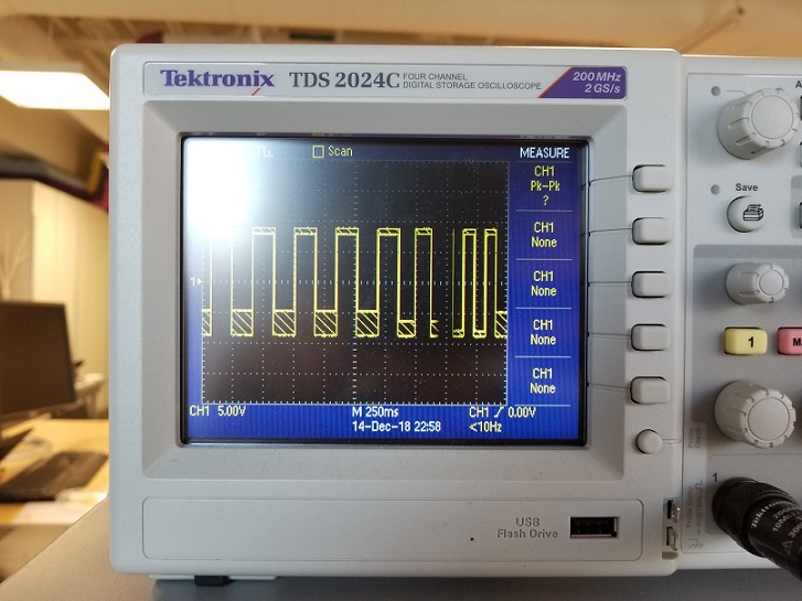
m328p hardware PWM, with bypass capacitor
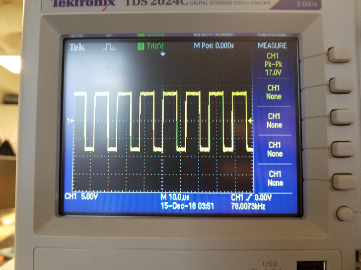
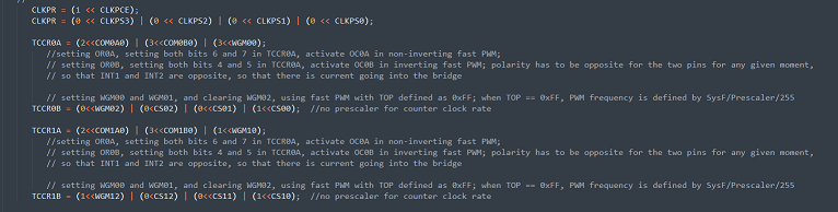
This is the register setting. I put 0xFF to be top for both counters, so that it is easy to pace the PWM for the two timer/counter, as one is an 8-bit, the other is a 16-bit.
By assembling the mechanical parts and testing the actual motion for given PWM settings, I am able to find the PWM settings for four direction states: forward/backward/TurnLeft/TurnRight, and an additional static state for the rover the stay still.
Loading a sequence of states into the ATMega, I tested the whole motor system.
Looking good!
The remaining issue is how to put all these into a solid rover, as now the driver board and the battery are just dangling when the rover moves.
The rover runs on a 9V battery, which is chosen because the A4953 chip will not work below 8V. The sticker driver board with the cardboard backing is about 5cm x 7.6cm.
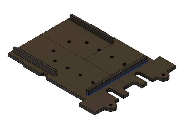
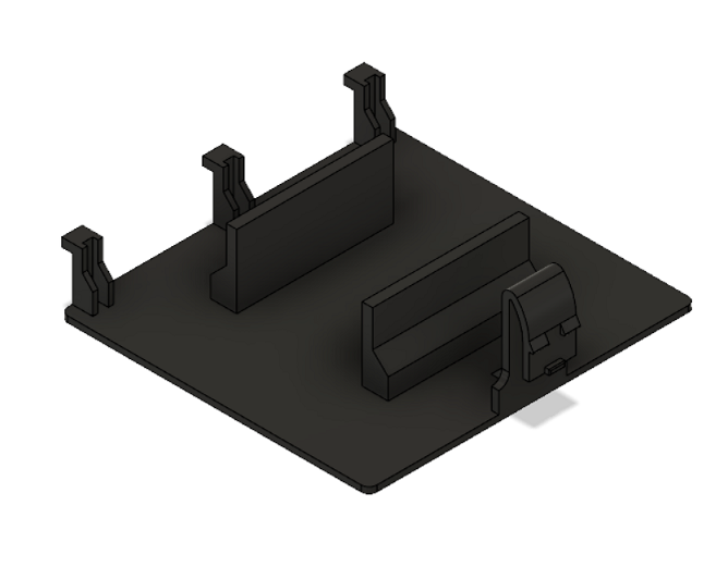
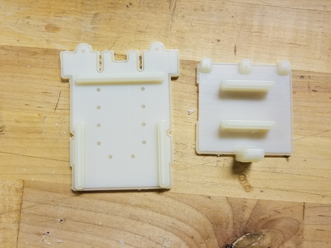
I design a mouting plate for the driver board and a battery holder for the 9V battery in fusion and have it 3D printed using the Eden polyjet printer.
Mounting Plate
Batter Holder
Print-out
With that, all the parts come together.
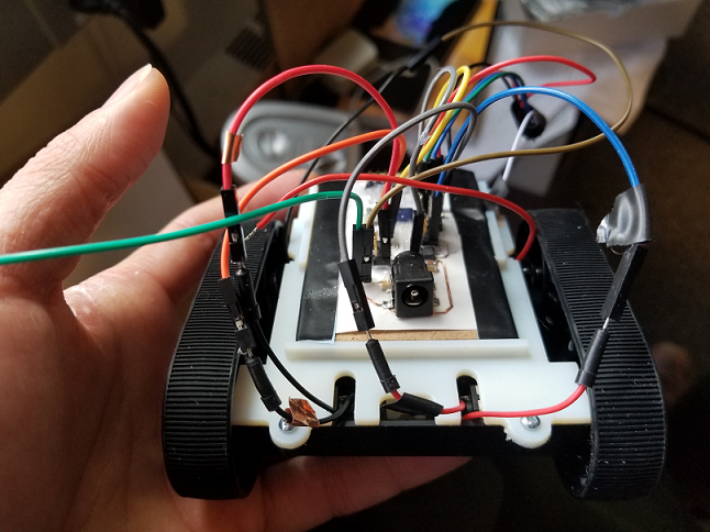
3. Networking
Using ATtiny44
My original thought was to use some estabilshed arduino library to save time. In the process, I found that ATttiny44 is not supported by the default serial library, and I had to use a library called software serial. As the software serial allows for repurposing pins for serial communication, I believe it is essentially a packaged bit-banging library.
I also need to use the ATtiny44 board definition by David Mellis.
Putting things together, I set up two software serial ports, one between the ATtiny44 and the bluetooth, the other between my laptop and the MCU, for debugging.
The plan is I will use the MCU to send in the ASCII commands to the bluetooth, and configure it into advertise modes, then I will have another bluetooth unit scan through the network and connect to the first one when it is found.
The initial trial seems ok, as I was able to achieve all of the above. But then I became doubtful of whether the MCU is actually talking to the bluetooth, as when I added one more line of command to stop advertising after the advertising command, I could still find the bluetooth unit in the network.
I decided to do a loop test on the MCU, sending in command to the MCU and have it echoed back. And it was working fine, except that sometimes, the MCU simply stops repsonding and also that within a while.available structure, serial.println no longer works, only blank lines are printed and the string contents are never shown. The first issue I believe is because the remaining memory space is low after loading the library content. The second I have not been able to find out why, but it basically limited the type of command I can send to be one byte(chr) each time, which I am concerned whether will affect the bluetooth configuration (previous terminal setup, I always sent in a string).

Using ATMega328
At this point, I decide to c-code the communication, as the previous issue from using arduino library is hard to debug because codes and definitions are so nested and packaged, whereas bit-banging is plain to understand. It also has the added benefit of significantly reduce memory usage.
To further simplify the system for debugging, I decides I will do serial communication for now and attack the bluetooth problem later.
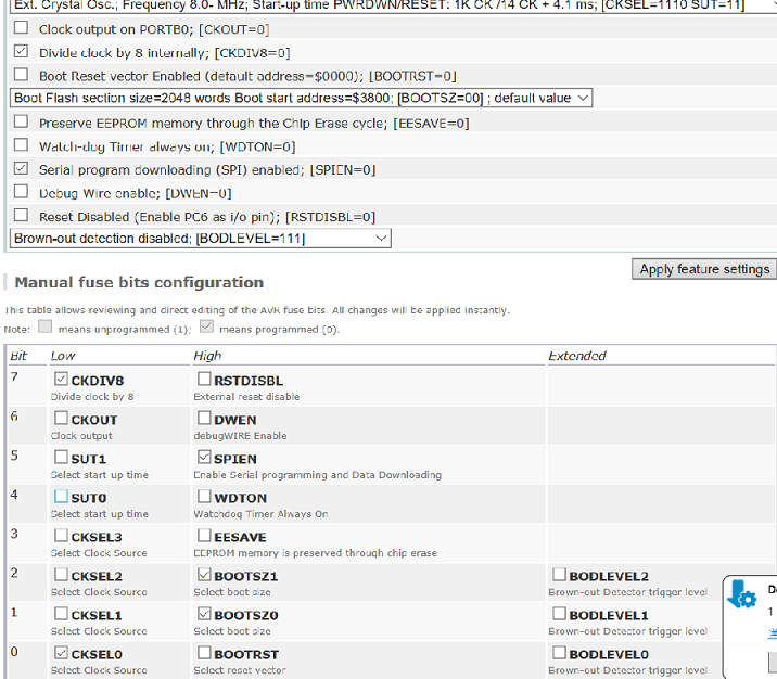
For precision timing, without which I suffered earlier when using an ATtiny44 without a external crystal, the fuse on the ATMega needs to be configured accordingly. Default fuse uses internal RC oscillator, and to use an external 20MHz crystal for ATMega328p, I need to set the low fuse to be 0x7E.
I configure the controller unit to send out a ASCII character at given interval. The specifca character to be sent is defined by the touch state of the capacitive sensors.
On the driver controller side, I have the microcontroller to be waiting for the character and based on that change or not change its motion states
The controller unit side seems to be working fine, as I was able to have the the character sent out and echoed back. Bit-bang loop test with no problem.
Since both the driver board and the controller board have 3.3 regulators, I use the 9V battery to power both the driver board and the control board, and have a serial communication channel between them for passing character command.
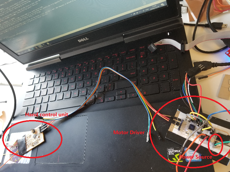
In a simplified test, the controller board will be constantly sending out character "W" for "wait", which the driver board ignores. When the electrodes touch, an indicator LED lights up and an "F" character for "forward" is sent out throught the serial channel, which the driver board takes and change the motion state of the rover.
The serial communication for complex motion series and wireless bluetooth version of it is work to continue.
But the rover does its job :)