Zijun Wei - How to Make Almost Anything
Week 3.
Electronic Design
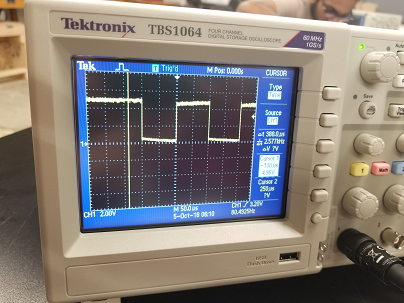
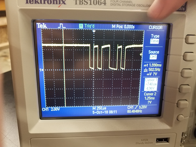
For group assignment, we learned to characterized a custom board using digital multimeter and oscilloscope. The exercise includes measuring the polarity of an LED, measure the voltage across it and various other components on the custom board. With the oscilloscope, we were able to read out the PWM waveform from the TX pin in the FTDI jack and a byte of information that the ATtiny44 was sending through the RX pin.
The individual assignment is to modify a board with an ATtiny44. The original board communicates with a desktop computer through an FTDI cable. On a python terminal, when the user types in a character or a string, the board would reply with the same content, and is therefore called the echo.hello.world board.
I would like my modified board to have these additional functionalities: An LED will have different light intensity whenever a button is pressed, and this mode can be turned on and off with a switch.
To do this, I added a switch, which connects the ground either, through a button, to the PA2 or, directly, to thePA3 of the ATtiny44. Addtionally, an LED, with its current-limiting resistor, is connected to the PA7 and to the ground. As shown below in the eagle board layout:
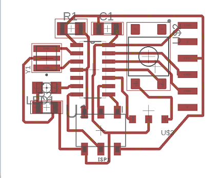
Using the layout png file generated with eagle, the board cut-out from the mill looks like this.
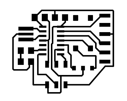
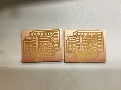
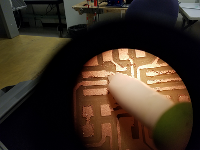
There was some copper peel-off from the edge of the traces. This peel-off is probably due to the end-mill being over-used, since switching to a different end-mill solved the issue(board on the left: new end-mill; board on the right: old end-mill). I used a blade to remove the peel-off from the board under a microscope.
Next is soldering the parts onto the board. The button pins at the fab lab does not quit fit the pads on my board, and I had to bend them a bit to make the connection. Also, to avoid shord circuit, I had to use some Kapton tape to cover part of the exposed traces.
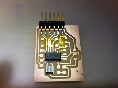
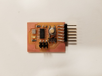
After soldering, the board looks in shape:
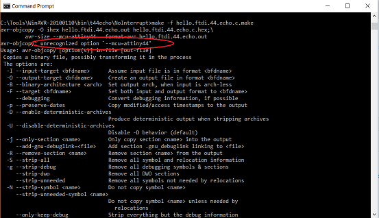
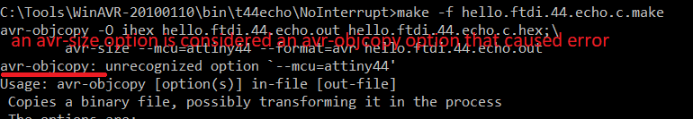
To test fabrication of the board, I first tried to upload the original program found on the FabClass website. To do that I use the WinGND32, which allows me to invoke the make command that I cannot invoke otherwise. On running this command:
make -f hello.ftdi.44.echo.c.makeI encountered this error of "unrecognized option":
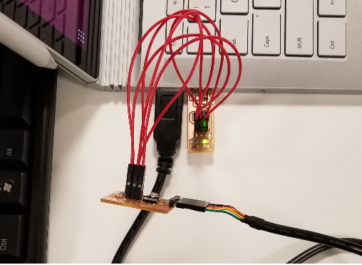
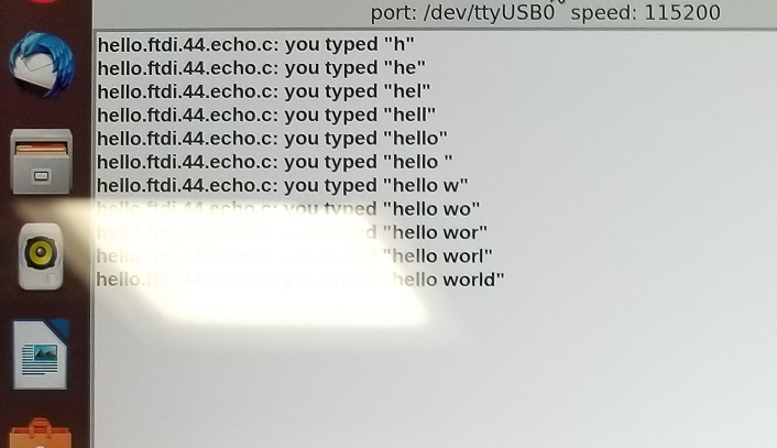
Not knowing what the cause was initially, and to implement the testing, I borrowed a laptop with Linux OS installed. To upload the program, I first connected the ISP pins correspondingly from the programmer(FabISP) to the programmee(the board that I modified this time), then use an FTDI-usb cable to connect the modified board to a laptop usb hub(this is to provide the board with power only), and plug the FabISP into another laptop usb hub. Following the tutorial here, I was able to upload the program to the board, type in "hellow world" and had it echoed back from the tiny44 through a python terminal.
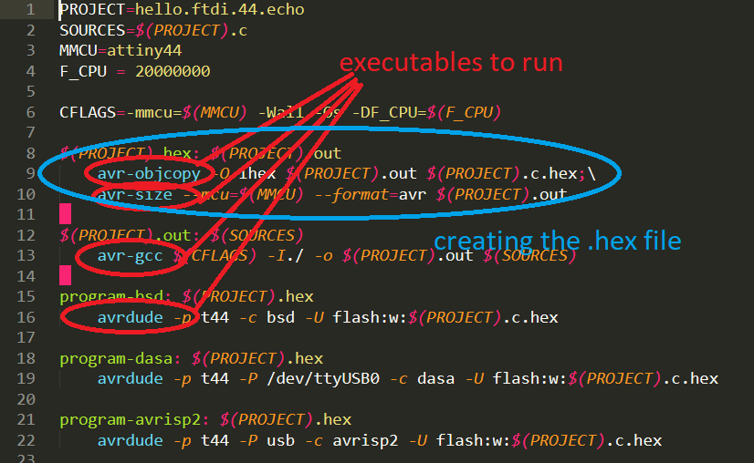
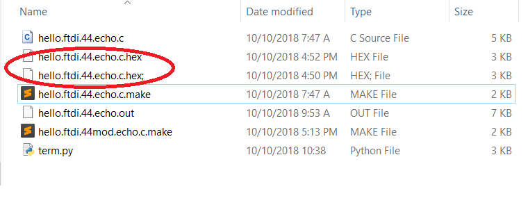
In revisiting the Windows OS programming issue, looking into the content of the makefile and talking with cohort, I learned that the Makefile "hello.ftdi.44.echo.c.make" actually generates the hex file to be uploaded into the MCU. In Linux, the MAKE command generates two files, .hex is the one to be uploaded, and .out is the logfile.
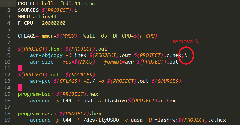
In my case, when trying to make that Makefile on Windows OS, only an .out file is made, and the .hex file was never created. Looking into the content of the Makefile, I got to know that what it does essentially is to invoke several avr-related executables, among which are avr-objcopy and avr-size, both are for making the .hex file needed. And the option "--mcu" is supposed to be called for avr-size, but instead, claimed to be a cause of error for avr-objcopy.
This suggests that root of the problem might be syntactic, that the makefile is written for Linux, but is interpreted differently on Windows. By removing the backslash \, I was able to have a ".hex;" file, which is still not usable, but definitely means that the ;\ on the first line is unnecessary for Windows OS makefile. And removing them both gave a nice .hex file I was looking for.
The follwoings are to be continued
To achieve the desired function, I modified the original c code to have the followings: 1. Enable Global interrupt 2. Interrupt pins 3. PWM setting
This C code is then compiled using the into a hex file, which is then loaded into the Tiny44 using avrdude and an ISP() through the SPI jack.
To test the functionality after programming, the modified board is powered through an FTDI cable, a the switch is turn to the on state, and then the button is pressed
To further modify the board,