Zijun Wei - How to Make Almost Anything
Week 7.
Embedded Programming
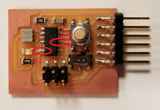
Continuing on the modified ATtiny44 board.
I would like my modified board to have these additional functionalities: An LED will have different light intensity whenever a button is pressed, and this mode can be turned on and off with a switch.
To do this, I need to have a pin reading the state of the button, activate the PWM of the ATtiny, and map the button press state to PWM state.
Start with the button detection. To my knowledge, there are two ways to do this: 1. Polling the state of the button constantly (once every system clock cycle?); 2. Use pin change interrupt.
1. Interrupt Method
I was intially concerned that polling the button will consume too much system resources, which I later learned that it is actually a common practice, and therefore started with the interrupt method.
In a nutshell, what I want to achieve is this: the MCU maintains its normal operation (e.g. LED maintains its intensity) and only triggers a change (in my case, a change in led intensity) only when the button is pressed. To do this, I need a sense pin, which triggers an event handler when the button is pressed, and a drive pin, that effects the changes made in the event handler into the LED state.
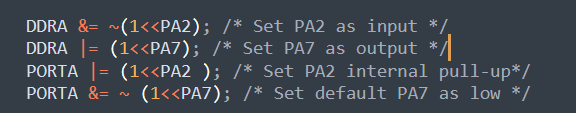
For the sense pin, I used the PA2 as the interrupt pin. I set PA2 to be input pin and set up the internal pull-up, so that by default a PINA readout should be logic high. The button connects this pin, through a switch(so that it can be toggled on and off), to the ground. When the button is pressed, PA2 will be shorted to the ground, which leads to PINA readout of this pin to be logic low. For the drive pin, I use PA7, which connects to the LED, and set as output. A logic high state of PA7 will turn on the LED, and a low state will turn it off. PWM is setting the on and off time within given period, which determines the average power going through the LED, and hence its intensity.
To set up PA2. According to the datasheet page 2, PA2 has the alternative function of PCINT2, which reads as pin-change interrupt 2. The follwing code will set it up, as an input pin, with internal pull-up:
To set up the PCINT2, we need to add the vector name to the argument in the interrupt service routine (ISR):
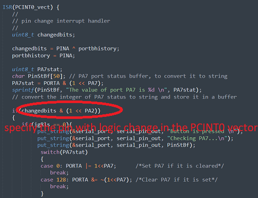
Now, when I press the button, the logic change will trigger the ISR, in which I set the state of the LED. In this stage, I am only using it to turn the LED on and off.
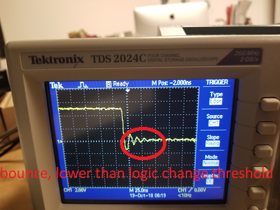
There is the concern that the reading of button state will bounce, since the contact usually fluctuates before reaching a steady state. I checked with a scope and it seems that the bounce is not significant enough to be taken as logic change, probably because the button is still new.
2. Polling Method
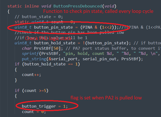
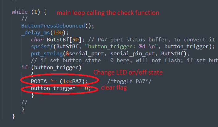
The polling method is a bit more straigthforward. I set up the I/O states of PA2 and PA7 as before, but this time, I only need to define function that is called every loop cycle to check PA2 logic state, and will set a flag when it is pulled low. Additionally, an if condition is added that will trigger an LED state change whenever the previous function call sets the flag, and clears the flag after the LED state change:
PWM setting
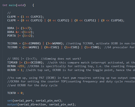
I intially wanted to use the internal PWM functionality, i.e. using the timer/counter peripheral. PA7 is also OC0B, which reads as Timer/Counter0 Compare Match Output B, or the compare match output channel B for timer/counter0. To set this up, I set the following registers: TCCR0A, TCCR0B, TIMSK0, and OCR0B, specifically these bits: COM0B1:0, for choosing the output channel; CS2:0, for choosing the clock prescalar and start the timer/counter0; and WGM2:0, for setting the output waveform.
Using this set up, I expect a set up of prescaler of 1024, non-inverting, fast PWM, output through OC0B.
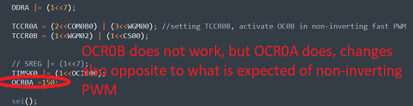
I expect by changing the OCR0B register, I will be able to change the PWM duty cycle and therefore LED intensity. This was not working unfortunately. The LED stayed constantly with max intensity. And by reading TCNT0 value and feeding it back through the serial, it seems that it is always showing 0, possibly meaning the timer/counter0 is not active?
Strangely, if istead of setting OCR0B, I set OCR0A, which according to my understanding of the datasheet, corresponds to PB2 pin, the intensity of the LED can be change. An OCR0A = 1 is leads to an LED intensity signifcantly higher than an OCR0A = 255.
In the end, I had to use the main loop to achieve PWM, in a not very efficient way.
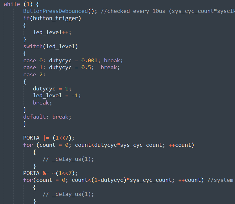
When combining this for-loop PWM scheme and button state check, the button is not working, which I needs to debug beyond the end of this log.
Revisiting the PWM and finishing the original scheme 10/31
There are two types of PWM:
1. Software PWM:
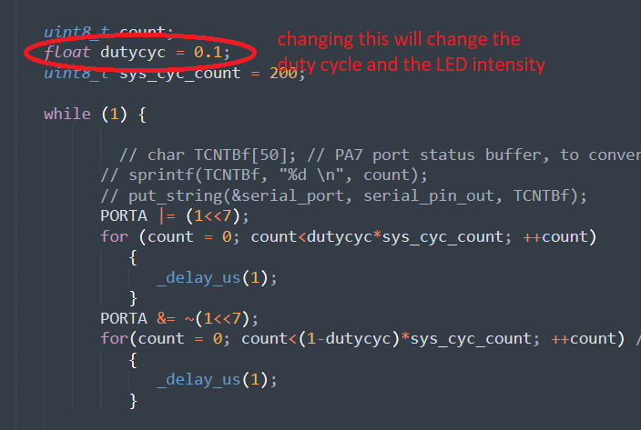
Writing for/while loop and setting up counter in the main loop. When the counter reach a certain tag value, toggle the output pin logic state. System clock set the pwm frequency, changing the tag value will change the duty cycle. However, this takes up a lot of resources in the main loop, and the duty cycle setting is limited. This is the case in the previous working implementation.
2. Hardware PWM:
Using the timer/counter intrinsic to the MCU by setting the corresponding register. ATtiny44, and likewise for many AVR, has built-in timers/counters. One can set the MCU registers so that when the counter reaches a certain value, something is triggered. This can used for interrupt event handling through ISR, and can also be used for toggling the logic state of an output pin at particular intervals, which is the hardward essential of a PWM. By setting the timer/counter reset value (the value which once the counter reaches, it goes back to zero), one sets the PWM frequency, and by setting the toggle value (the value once the counter reaches, the output pin toggles its state), we set the duty cycle of the PWM.
This is a more efficient way to set PWM, as the timer/counter can be running in the background, and more syncrhonized with the main loop, without taking up much space in the latter either. And this is the implementation I would like to achieve initially last time but did not suceed.
By reading through the datasheet again, I found that I had a misconception of the register functions. OCR0A indeed corresponds to the output compare value of timer/counter0 output channel A, as does OCR0B to that of timer/counter0 output channel B, these are the values that once reached by the timer/counter, something is triggered. But OCR0A is more than that in PWM modes(logic state toggling mode) and CTC mode, the latter of which is not covered here. According datasheet page 84, table 11-8, fast PWM and phase-correct pwm with a changeable TOP value(the value once reached by the timer/counter, the timer/counter resets), i.e. mode 5 and 7, OCR0A also set this TOP value, i.e. the PWM frequency.
Therefore in using mode 5 or 7 for output channel B (OCR0B, PA7), besides setting the OCR0B, which set the value for toggling, i.e. duty cycle, I also need to set the timer reset value in OCR0A, which I did not previously. To sum up, channel B, two registers, one for timer reset, OCR0A, the other for toggling, OCR0B. And since OCR0B sets the duty cycle, it must be some value smaller than that stored in OCR0A.
By making this correction as follows, I was able to achieve the button intensity switching, after combining this code with the button polling code.
For the current code, if I hold down the button long enough, the LED intensity will go through all levels. Adajcent states can sometimes be accidentally triggered if the press is a little long. I will modify the code further to make sure holding down does not trigger.
t44 HardwarePWM code